Industrial automation is full of complicated-looking wiring diagrams.
But behind many of those diagrams is a very simple idea:
Something is either ON or OFF.
A button is pressed or not pressed. A relay contact is open or closed. A sensor is detecting or not detecting. A motor contactor is energized or de-energized.
This two-state way of thinking is the foundation of Boolean logic.
Boolean logic may sound like a mathematical topic, but in automation it is extremely practical. It helps us understand relay circuits, PLC ladder logic, interlocks, start-stop circuits, alarms, permissives, and machine control sequences.
Once you understand Boolean logic, electrical control diagrams become much easier to read.
What Is Boolean Logic?
Boolean logic is a system of logic based on only two possible values.
These values are usually written as:
- 0
- 1
In electrical and automation systems, these values often represent:
| Boolean Value | Automation Meaning |
|---|---|
| 0 | OFF, open, inactive, false, no voltage |
| 1 | ON, closed, active, true, voltage present |
So, instead of thinking about unlimited values, Boolean logic only asks one question:
Is the condition true or false?
That is why Boolean logic fits automation so well. Many control devices work in two states.
A push button is either pressed or not pressed.
A relay contact is either open or closed.
A PLC input is either OFF or ON.
A motor output is either de-energized or energized.
This is binary thinking, and machines love it.
Binary Values in Electrical Circuits
The binary number system uses only two digits: 0 and 1.
In automation circuits, we can use those digits to describe electrical states.
For example:
- Motor stopped = 0
- Motor running = 1
- Contact open = 0
- Contact closed = 1
- Sensor inactive = 0
- Sensor active = 1
- PLC input OFF = 0
- PLC input ON = 1
This does not mean that 0 and 1 are always normal arithmetic numbers. In control logic, they are often symbols for a condition.
They can mean:
- False or true
- Low or high
- Open or closed
- OFF or ON
- Not energized or energized
The exact meaning depends on the system, but the two-state principle remains the same.
Boolean Variables
In Boolean logic, each switching element can be represented by a variable.
For example:
- A may represent a limit switch
- B may represent a push button
- C may represent a relay contact
- M may represent a motor contactor coil
- S may represent a sensor signal
Each variable can only have two possible values:
- 0
- 1
For example, if variable A represents a normally open push button, then:
- A = 0 when the button is not pressed
- A = 1 when the button is pressed
If variable M represents a motor contactor, then:
- M = 0 when the contactor is off
- M = 1 when the contactor is energized
This makes it possible to describe an automation circuit as a logical expression.
That sounds academic, but it is very useful in real troubleshooting and PLC programming.
The Three Basic Boolean Operations
Boolean algebra uses three main logic operations:
- OR
- AND
- NOT
These are the basic building blocks of relay logic and PLC logic.
In Boolean algebra, they are often written as:
| Logic Operation | Common Symbol | Meaning |
| OR | + | One condition or another must be true |
| AND | · | All conditions must be true |
| NOT | bar over variable or inverted symbol | Condition is reversed |
In automation language:
- OR means contacts in parallel
- AND means contacts in series
- NOT means normally closed or inverted logic
This is the bridge between mathematics and wiring.
AND Logic in Automation
AND logic means that all required conditions must be true before the output turns on.
In electrical wiring, AND logic is created by connecting contacts in series.
For current to reach the coil, every contact in the series path must be closed.
Example:
A motor can start only if:
- STOP circuit is healthy
- Overload is not tripped
- Guard door is closed
- START button is pressed
All conditions must be true.
That is AND logic.
A simple Boolean expression may look like this:
Motor = Stop_OK · Overload_OK · Guard_OK · Start
In plain English:
The motor output turns on only when Stop_OK, Overload_OK, Guard_OK, and Start are all active.
If even one of these conditions is false, the motor does not start.
Series contacts behave exactly like AND logic.
OR Logic in Automation
OR logic means that any one of several conditions can activate the output.
In electrical wiring, OR logic is created by connecting contacts in parallel.
If one parallel path is closed, current can flow.
Example:
A warning lamp may turn on if:
- Sensor A detects a fault
- Sensor B detects a fault
- Sensor C detects a fault
Any one fault condition is enough.
A Boolean expression may look like this:
Alarm = Sensor_A + Sensor_B + Sensor_C
In plain English:
The alarm turns on if Sensor A is active, or Sensor B is active, or Sensor C is active.
Parallel contacts behave like OR logic.
NOT Logic in Automation
NOT logic means inversion.
It changes the meaning of a signal to its opposite.
If A is 1, then NOT A is 0.
If A is 0, then NOT A is 1.
In automation, NOT logic is commonly represented by a normally closed contact or an inverted PLC contact.
For example, if a normally closed STOP button is healthy and not pressed, the circuit is closed. But when the button is pressed, the contact opens and the motor stops.
So the physical contact state can represent the opposite of the button action.
This is why normally open and normally closed contacts must be understood carefully.
A wrong assumption here can make the whole circuit behave backwards.
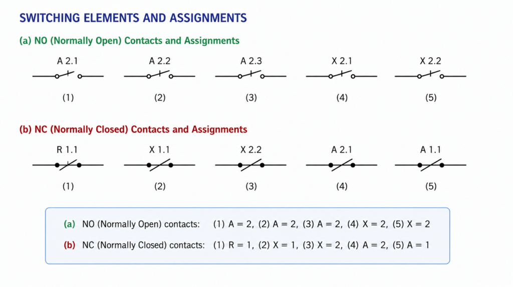
Normally Open Contact as a Boolean Variable
A normally open contact is open in its resting state.
For example, a START push button is usually normally open.
When the button is not pressed:
- Contact is open
- Current cannot pass
- Logic value may be considered 0
When the button is pressed:
- Contact closes
- Current can pass
- Logic value may be considered 1
So for a normally open push button named b, the output Z can be described as:
Z = b
This means the output follows the button.
Button not pressed, output off.
Button pressed, output on.
Simple and direct.
Normally Closed Contact as a Boolean Variable
A normally closed contact is closed in its resting state.
For example, a STOP push button is usually normally closed.
When the button is not pressed:
- Contact is closed
- Current can pass
When the button is pressed:
- Contact opens
- Current is interrupted
If variable b represents the action of pressing the button, then the output is the opposite of b.
This can be described as:
Z = NOT b
In plain words:
When the button is not activated, the circuit is active.
When the button is activated, the circuit is broken.
This is why normally closed contacts are often used for stop, safety, overload, and fault conditions.
They are naturally suited for interrupting control circuits.
Digital Voltage Levels
In electronic systems, Boolean values can also represent voltage levels.
For example, in many digital circuits:
- Low voltage represents logical 0
- High voltage represents logical 1
In classic TTL logic, a voltage near 0 V is treated as logic 0, and a voltage near +5 V is treated as logic 1.
In industrial automation, the voltage levels are often different. Many PLC systems use 24 V DC inputs and outputs.
For example:
| PLC Input Voltage | Typical Logic Meaning |
| 0 V | Input OFF, logic 0 |
| 24 V DC | Input ON, logic 1 |
The exact voltage thresholds depend on the PLC and input module, but the idea is the same.
Low voltage means 0.
High voltage means 1.
The PLC program then uses those 0s and 1s to make decisions.
Boolean Logic and PLC Inputs
A PLC input is basically a Boolean variable.
A sensor or switch sends voltage to the PLC input. The PLC reads that input as either OFF or ON.
For example:
- Input I0.0 = START button
- Input I0.1 = STOP button
- Input I0.2 = overload contact
- Output Q0.0 = motor contactor
Each input is treated as a logical state.
The PLC program then combines those states using AND, OR, and NOT logic.
This is why Boolean logic is so important for PLC programming. Ladder logic is basically Boolean logic drawn like an electrical circuit.
Series Contacts Equal AND Logic
In relay circuits and ladder logic, contacts in series mean AND.
For example:
A in series with B in series with C
The output turns on only if A, B, and C are all closed.
Boolean expression:
Z = A · B · C
Truth table:
| A | B | C | Z |
| 0 | 0 | 0 | 0 |
| 0 | 0 | 1 | 0 |
| 0 | 1 | 0 | 0 |
| 0 | 1 | 1 | 0 |
| 1 | 0 | 0 | 0 |
| 1 | 0 | 1 | 0 |
| 1 | 1 | 0 | 0 |
| 1 | 1 | 1 | 1 |
Only one row gives output 1.
All conditions must be true.
That is AND logic.
Parallel Contacts Equal OR Logic
Contacts in parallel mean OR.
For example:
A in parallel with B
The output turns on if A is closed, or B is closed, or both are closed.
Boolean expression:
Z = A + B
Truth table:
| A | B | Z |
| 0 | 0 | 0 |
| 0 | 1 | 1 |
| 1 | 0 | 1 |
| 1 | 1 | 1 |
Only when both contacts are open does the output stay off.
This is OR logic.
In practical automation, this is used when several different commands can activate the same output.
Mixed Logic in Automation Circuits
Real automation circuits often use series and parallel contacts together.
For example, a motor may start if:
- STOP is healthy
- Overload is healthy
- Guard is closed
- And either START button or automatic sensor command is active
Boolean expression:
Motor = Stop_OK · Overload_OK · Guard_OK · (Start + Auto_Command)
This means the safety and permission contacts are required in all cases, but the motor command can come from either the manual START button or the automatic sensor.
That is a mixed AND/OR circuit.
In relay wiring, this would be a combination of series and parallel contacts.
In PLC ladder logic, it would look almost the same visually.
Boolean Logic and the Latch Circuit
The classic start-stop latch circuit is a perfect example of Boolean logic.
A motor contactor coil can be controlled by:
- STOP button
- START button
- Its own auxiliary holding contact
The simplified Boolean expression is:
C = STOP · (START + C)
Where:
- C = contactor coil energized
- STOP = stop circuit is closed/healthy
- START = start button is pressed
- C inside the brackets = auxiliary self-latching contact
This means:
The contactor is energized if the STOP path is healthy and either the START button is pressed or the contactor is already energized.
That is the latch principle written as Boolean logic.
The same idea appears in relay diagrams and PLC ladder programs.
This is why Boolean expressions are not only theory. They describe real machine behavior.
Logical Functions
A logical function describes how one output depends on one or more input variables.
For example:
Z = f(A, B, C)
This means output Z depends on input variables A, B, and C.
In automation, Z could be:
- A motor output
- A relay coil
- A lamp
- A valve
- A PLC output
- An alarm bit
And A, B, and C could be:
- Push buttons
- Sensors
- Relay contacts
- Safety contacts
- Timer contacts
- PLC internal bits
A logical function can be simple or complex.
Simple example:
Z = A
Output follows input A.
More complex example:
Z = A · B + C
Output turns on if A and B are both true, or if C is true.
This is exactly how automation logic is built.
Boolean Logic Gates
In electronics, Boolean operations are often represented by logic gates.
The three basic gates are:
- AND gate
- OR gate
- NOT gate
An AND gate gives output 1 only when all inputs are 1.
An OR gate gives output 1 when at least one input is 1.
A NOT gate inverts the input.
In hardwired relay control, we do not always draw gates. We draw contacts and coils instead.
But the logic is the same.
Series contacts are an AND gate.
Parallel contacts are an OR gate.
Normally closed or inverted contacts are NOT logic.
PLC ladder logic also follows this same idea.
That is why learning Boolean gates helps with both electronics and automation wiring.
Truth Tables
A truth table shows all possible input combinations and the resulting output.
For simple logic, truth tables are very useful.
For AND:
| A | B | Z = A · B |
| 0 | 0 | 0 |
| 0 | 1 | 0 |
| 1 | 0 | 0 |
| 1 | 1 | 1 |
For OR:
| A | B | Z = A + B |
| 0 | 0 | 0 |
| 0 | 1 | 1 |
| 1 | 0 | 1 |
| 1 | 1 | 1 |
For NOT:
| A | Z = NOT A |
| 0 | 1 |
| 1 | 0 |
Truth tables are helpful when designing circuits because they force you to define exactly what should happen.
No guessing.
No “it should probably work.”
The output is either 0 or 1 for every possible input state.
Boolean Logic in Relay Circuits
Relay circuits are physical Boolean logic.
Each contact represents a condition. Each coil represents an output. The circuit wiring defines the logical relationship between them.
For example:
- Contacts in series create required conditions
- Contacts in parallel create alternative paths
- NC contacts create inverted logic
- Relay coils create output states
- Auxiliary contacts create memory or interlocking
This is how older automation systems were built before PLCs became common.
And many machines still use relay logic today, especially for simple controls, safety circuits, and contactor interlocking.
Even when a PLC is used, the same logic still exists.
Only the implementation changes.
Boolean Logic in Ladder Diagrams
Ladder logic programming is strongly based on relay logic.
A ladder rung works like a control circuit branch.
The left side represents supply logic. The right side contains the output coil.
Contacts placed in series act like AND logic.
Contacts placed in parallel act like OR logic.
Normally closed contacts act like NOT logic.
For example:
START contact in series with STOP contact controlling MOTOR coil
This is the same idea as a hardwired circuit.
That is why electricians and maintenance technicians often find ladder logic easier to understand than text-based programming.
It looks like wiring.
Because historically, it comes from wiring.
Why Boolean Logic Matters in Troubleshooting
Boolean logic is not only for design. It is also useful for troubleshooting.
When a machine output is not turning on, ask:
Which logical condition is missing?
For example, if a motor contactor does not energize, the logic might require:
- Safety relay OK
- STOP button closed
- Overload contact closed
- Guard switch closed
- Start command active
- No fault active
If the motor output is off, one of these conditions may be false.
Instead of randomly checking wires, Boolean thinking helps you follow the logic.
Find the 0 that should be 1.
Or find the 1 that should be 0.
That is troubleshooting in one sentence.
Common Mistakes With Boolean Logic
Beginners often struggle with Boolean logic because physical contact state and logical meaning can be confusing.
Common mistakes include:
- Confusing normally open with normally closed
- Thinking contact drawing always shows active state
- Forgetting that PLC contacts may represent software logic, not physical contact shape
- Mixing up button action and contact state
- Misreading series contacts as OR logic
- Misreading parallel contacts as AND logic
- Forgetting that a normally closed stop contact opens when pressed
- Using inverted logic without labeling it clearly
- Ignoring the difference between sensor active state and output contact state
The biggest mistake is assuming that the symbol tells the whole story.
You also need to know what the variable means.
Does A mean “button pressed”?
Or does A mean “contact closed”?
Those are not always the same thing.
Practical Example: Simple Start Permission
Imagine a machine can start only if a guard door is closed and a start button is pressed.
Let:
- G = guard door closed
- S = start button pressed
- M = motor command
The logic is:
M = G · S
The motor runs only when both conditions are true.
If the guard door is open, the motor cannot start.
If the start button is not pressed, the motor cannot start.
Both are required.
That is AND logic.
Practical Example: Two Start Buttons
Imagine a machine can be started from either of two control panels.
Let:
- S1 = start button 1
- S2 = start button 2
- M = motor command
The logic is:
M = S1 + S2
The motor command becomes active if either start button is pressed.
That is OR logic.
In wiring, the two start buttons would be connected in parallel.
Practical Example: Stop Condition
Imagine a motor should run only when a fault is not active.
Let:
- F = fault active
- Run_Permit = allowed to run
The logic is:
Run_Permit = NOT F
If there is no fault, the run permit is true.
If the fault becomes active, the run permit becomes false.
This is NOT logic.
In a relay circuit, this may be done with a normally closed fault contact.
In a PLC, it may be done with an inverted contact or a NOT instruction.
From Contacts to Logic
The most important takeaway is this:
Automation circuits can be translated into Boolean expressions.
And Boolean expressions can be translated into automation circuits.
Series contacts become AND.
Parallel contacts become OR.
Normally closed contacts become NOT.
Coils become outputs.
Once you understand that, you can move between wiring diagrams, relay logic, PLC ladder logic, and logical expressions much more easily.
That is why Boolean logic is one of the foundations of automation design.
Final Thoughts
Boolean logic is the language behind many automation circuits.
It uses only two values, 0 and 1, to describe states such as OFF and ON, open and closed, inactive and active, false and true.
In automation, switches, sensors, relay contacts, PLC inputs, and output coils can all be treated as Boolean variables. Series connections represent AND logic. Parallel connections represent OR logic. Normally closed or inverted contacts represent NOT logic.
This makes it possible to describe even complex relay and PLC control circuits with logical functions.
A simple push button can be written as a Boolean variable. A stop-start latch circuit can be described with a Boolean equation. A complete machine sequence can be built from combinations of AND, OR, and NOT.
At first, it looks like mathematics.
In practice, it is just machine decision-making.
Is the sensor active?
Is the stop circuit healthy?
Is the overload reset?
Is the start command present?
If the right answers are true, the output turns on.
That is Boolean logic in industrial automation.