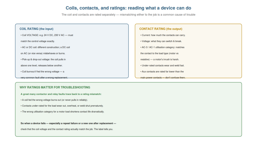
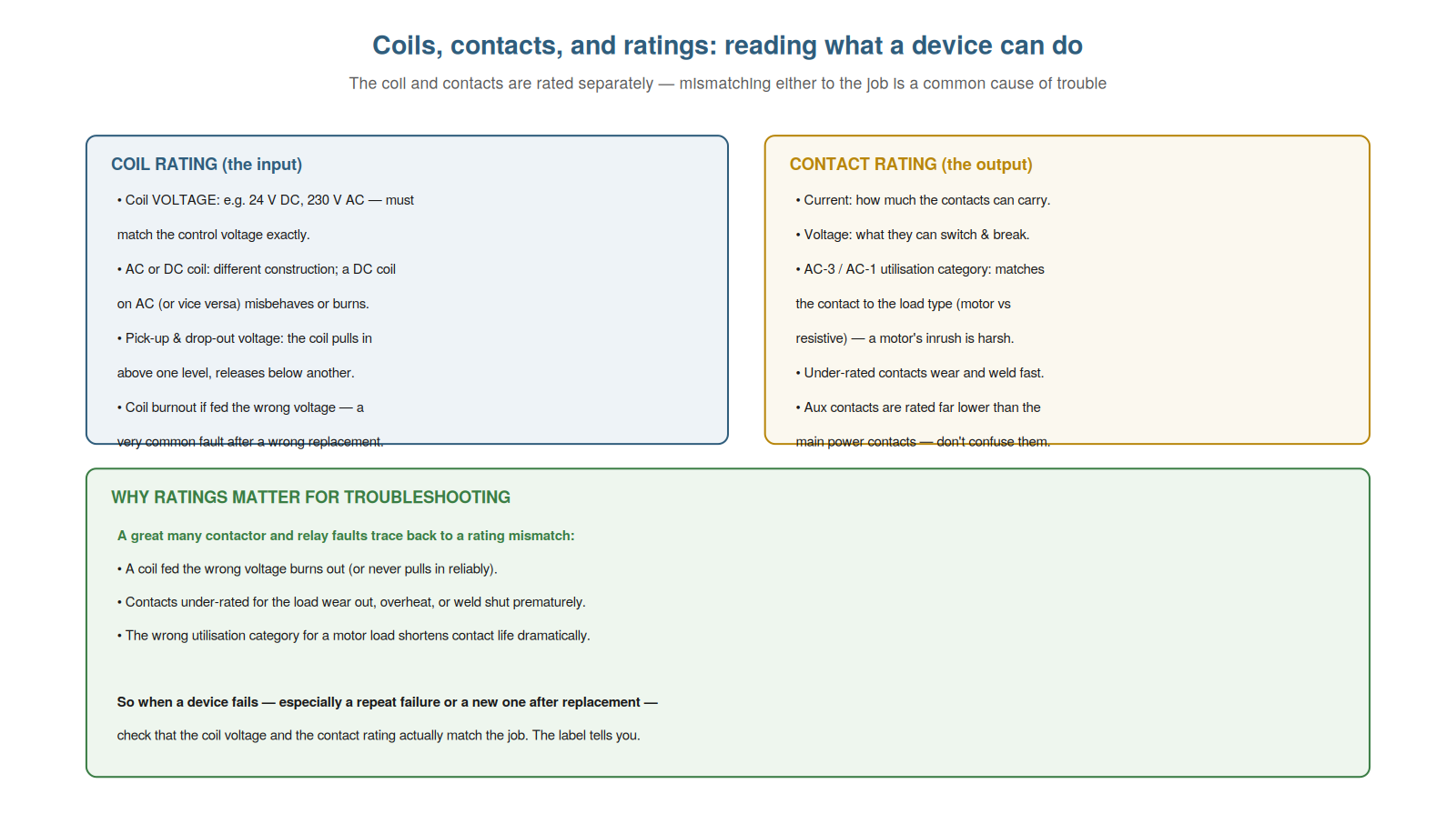
Contactors and relays are defined by two sets of specifications — the coil rating (the input) and the contact rating (the output) — and understanding these ratings is important because a great many faults trace back to a mismatch between a device’s rating and its job. A coil fed the wrong voltage burns out; contacts under-rated for their load wear and weld prematurely. Understanding what the ratings mean lets you both avoid these faults and recognize them when a device fails. This chapter covers coils, contacts, and ratings from the maintenance perspective.
Coil ratings and the wrong-voltage trap
The coil’s key rating is its voltage (and AC or DC type), and understanding this — and the trap of feeding a coil the wrong voltage — explains one of the most common faults, especially after a replacement. A coil is made for a specific voltage (24 V DC, 110 V AC, 230 V AC, 400 V AC, and so on) and for either AC or DC operation; it must be fed the voltage it was made for. Feeding a coil the wrong voltage causes trouble: too high a voltage overheats and burns out the coil; a DC coil on AC (or vice versa) misbehaves — an AC coil relies on the AC construction, and a DC coil has different resistance and no such design. The trap is especially common after a replacement: someone fits a coil (or a whole contactor) with the wrong coil voltage, and it burns out or fails to work. Understanding coil ratings lets you both avoid this (match the coil to the control voltage) and diagnose it (a burnt coil, especially a repeat failure, points to a wrong-voltage or over-voltage problem). So understanding coil ratings and the wrong-voltage trap explains and helps you avoid a very common fault. Understanding coil ratings and the wrong-voltage trap — that a coil is made for a specific voltage and AC/DC type, and feeding it the wrong voltage burns it out or makes it misbehave, a common error after replacement — explains one of the most frequent contactor and relay faults, so that you both avoid it (matching the coil marking to the actual control voltage) and diagnose it (recognizing a burnt-out coil, especially a repeat burnout, as a sign of the wrong coil voltage, wrong type, or an over-voltage supply), which addresses the wrong-voltage coil failure that maintenance technicians meet so often, particularly in the aftermath of a well-meant but mismatched replacement.
Contact ratings and utilisation categories
The contacts’ ratings — current, voltage, and utilisation category — define what they can switch, and understanding them, especially the utilisation category, explains why under-rated or wrongly-categorized contacts fail prematurely. The contacts have a current rating (how much they can carry), a voltage rating (what they can switch and break), and a utilisation category (like AC-3 for motors or AC-1 for resistive loads) that matches the contact to the type of load. The utilisation category matters because different loads are differently harsh: a motor draws a heavy inrush current on starting and is inductive, so switching it (category AC-3) is far more demanding than switching a resistive load (AC-1). A contact under-rated for its current, or of the wrong category for its load, wears out, overheats, or welds prematurely because it is being asked to switch more than it was designed for. Understanding contact ratings and categories lets you recognize this cause: a contactor whose contacts wear or weld quickly may be under-rated or wrongly categorized for its load. So understanding contact ratings and utilisation categories — what the contacts can switch, matched to the load type — explains premature contact failure from a rating mismatch. Understanding contact ratings and utilisation categories — the current and voltage the contacts can switch, and the utilisation category (AC-3 for motors, AC-1 for resistive loads) matching the contact to the harshness of the load — explains why under-rated or wrongly-categorized contacts fail prematurely, so that you recognize a contactor whose contacts wear, overheat, or weld quickly as possibly under-rated or of the wrong category for its load (a motor’s inrush being far harsher than a resistive load), which identifies a rating mismatch as the cause of premature contact failure and directs you to check the contact rating against the actual load when contacts fail too soon.
Reading the label
The practical skill that brings the ratings together is reading the device’s label, and understanding how to read it lets you check a device against its job — essential for both selection and diagnosis. A contactor or relay is marked with its key ratings: the coil voltage (and AC/DC), the contact current and voltage ratings, and often the utilisation category and other data. Reading the label tells you what the device is: what voltage its coil needs, what its contacts can switch. This lets you check the device against its job — does the coil voltage match the control voltage? are the contacts rated for the load? — which is how you both select a correct replacement and diagnose a rating-mismatch fault. When a device fails, especially repeatedly or after a replacement, reading its label and comparing to the actual application often reveals a mismatch: a wrong coil voltage, under-rated contacts. So reading the label is the practical means of applying rating knowledge to real devices. Understanding how to read the label — the coil and contact ratings marked on the device — lets you check a device against its job for both selection and diagnosis. Understanding how to read the label — the coil voltage and type, the contact current and voltage ratings, and the utilisation category marked on a contactor or relay — lets you check a device against its job, so that you can verify the coil voltage matches the control supply and the contacts are rated for the load, which is essential both for selecting a correct replacement and for diagnosing a rating-mismatch fault by comparing a failed device’s label to its actual application, revealing the wrong coil voltage or under-rated contacts behind so many contactor and relay failures.
KNOW THE COIL AND THE CONTACTS, BEFORE YOU REACH FOR THE METERAlmost every contactor and relay fault resolves into one of two questions: is the coil doing its job, and are the contacts doing theirs? Before measuring, be clear which you are testing — the input (coil) or the output (contacts) — and what a healthy result would be. Read the device’s ratings so you know what ‘healthy’ means: the coil’s rated voltage, the contacts’ rated load. A technician who splits every fault into coil and contacts, and knows the ratings, measures with purpose; one who does not simply swaps the whole device and hopes. Understand the coil and the contacts, then confirm with the meter. |
Coil power consumption and control-supply loading
A practical detail worth understanding is a coil’s power consumption and its effect on the control supply, because it explains some supply-loading problems. Each energized coil draws some power from the control supply (its VA or watts), and a contactor coil (especially a large AC one with high inrush) can draw significant power, particularly at the moment of energizing. When many coils are energized, or several energize at once, the total load on the control supply can be substantial — and if the supply is undersized or already loaded, energizing coils can sag its voltage. Understanding this explains a class of problems: a control supply pulled down by coil loading (causing chatter or drop-outs of marginally-fed coils), or an AC coil’s inrush momentarily loading the supply. It also matters for the control contacts switching the coils: they must handle the coil’s current, including inrush. So understanding coil power consumption and control-supply loading explains supply-sag and contact-loading problems. Understanding a coil’s power consumption and its effect on the control supply — each coil drawing power (a large AC coil with high inrush drawing significant power, especially at energizing), which loads the control supply and can sag its voltage if it is undersized or heavily loaded — explains supply-loading problems, so that you understand how energizing coils can pull down a control supply (causing chatter or drop-outs) and stress the control contacts switching them with inrush current, which connects the coil’s power draw to the supply-sag and contact-loading problems that can arise in a control system with many or large coils.
Scenario: the coil that kept burning out
A scenario shows how understanding ratings solves a repeat failure. A contactor’s coil kept burning out — replaced, it would burn out again within days — baffling the team until the technician thought about the coil rating. Understanding that a coil burns out from the wrong voltage, he read the coil marking and compared it to the actual control voltage: the coil was rated 230 V, but the control circuit was 400 V. Each replacement coil, fed 400 V when made for 230 V, overheated and burned out. The root cause was a wrong-voltage coil being fitted (someone had originally fitted a 230 V coil where 400 V was applied). Fitting the correct 400 V coil ended the repeat burnouts. Understanding coil ratings — that the coil voltage must match the supply — solved a repeat failure that swapping identical wrong coils never would. This scenario shows how understanding ratings solves a repeat coil burnout. Understanding that a coil burns out from the wrong voltage led the technician to compare the coil marking to the actual supply and find the mismatch. It reinforces that a repeat coil burnout points to a wrong-voltage or over-voltage cause found by checking the rating. The scenario reinforces understanding ratings: knowing a coil burns out when fed the wrong voltage led the technician to compare the coil marking to the actual control voltage and find a 230 V coil on 400 V, illustrating how understanding coil ratings solves a repeat burnout by revealing the voltage mismatch that swapping identical wrong coils would never fix, addressing the cause rather than the symptom.
Coil economizers and electronic coils
A nuance in modern contactors worth understanding is the coil economizer or electronic coil, because it changes the coil’s behavior and some faults. Traditional AC coils draw high inrush then lower holding current mechanically (as the armature seats). Many modern contactors use an electronic coil control (an economizer circuit) that manages the coil current electronically: a higher current to pull in, then a reduced current to hold, achieving lower power consumption and often accepting a wide range of voltages (a single coil working across, say, 24–60 V or 100–250 V). Understanding this explains some behaviors: an electronic coil may accept a range of voltages (so ‘wrong voltage’ is less of an issue within its range, but outside it still fails), and it has electronics that can themselves fail (a fault in the economizer, not the winding). So a modern contactor’s coil may not behave like a simple winding — it may be a wide-range electronic coil with its own control circuit. Understanding coil economizers and electronic coils explains their wide-range behavior and electronic failure modes. So understanding coil economizers and electronic coils explains modern coil behavior and faults. Understanding coil economizers and electronic coils — the electronic control managing the coil current for lower power and often a wide voltage range, versus a simple winding — explains modern coil behavior and faults, so that you understand a modern contactor’s coil may accept a range of voltages (making ‘wrong voltage’ less likely within range but still failing outside it) and has electronics that can fail independently of the winding, which updates your understanding of coils beyond the simple winding to include the wide-range electronic coils common in modern contactors and their particular behaviors and failure modes.
Ratings as the key to lasting repairs
To close, it is worth emphasizing that understanding ratings is the key to lasting repairs, because so many repeat failures come down to a rating mismatch. A device that fails once may be a genuine failure; a device that fails repeatedly usually has a cause, and a rating mismatch — a wrong coil voltage, under-rated or wrongly-categorized contacts — is among the most common. Understanding ratings lets you both make a lasting repair (fitting a correctly-rated replacement) and diagnose a repeat failure (recognizing the mismatch behind it). So ratings are the key to lasting repairs: without matching them, a replacement may fail as the original did; with them, the repair lasts. This is why reading the label and matching the ratings is not a formality but the difference between a fix and a repeat failure. So understanding ratings as the key to lasting repairs shows why matching them matters. Understanding ratings as the key to lasting repairs — that many repeat failures come down to a rating mismatch (wrong coil voltage, under-rated or wrongly-categorized contacts), so matching the ratings is what makes a repair last — shows why reading the label and matching the ratings is not a formality but the difference between a fix and a repeat failure, so that you both make lasting repairs (fitting correctly-rated replacements) and diagnose repeat failures (recognizing the mismatch behind them), which is why understanding ratings is central to resolving contactor and relay faults for good rather than watching a replacement fail as the original did.