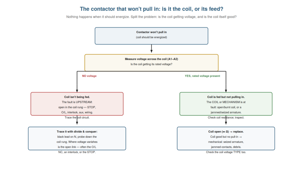
A contactor that will not pull in — nothing happens when it should energize — is one of the most common faults, and the method for diagnosing it is the heart of contactor troubleshooting: split the problem into whether the coil is getting voltage and whether the coil itself is good. This single split — is the coil fed? is the coil good? — directs you immediately to the right half of the problem. Understanding this method equips you for the won’t-pull-in fault and embodies the book’s core approach. This chapter covers it in detail.
The one measurement that splits the fault
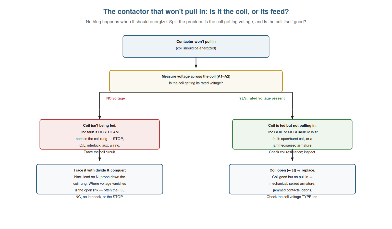
The key to the won’t-pull-in fault is one measurement that splits it in two, and understanding this measurement directs your whole diagnosis. The measurement is the voltage across the coil terminals (A1–A2) when the contactor should be energized. This one reading splits the fault: if there is no voltage (or too little), the coil is not being fed — the fault is upstream in the coil circuit, and you trace that. If the rated voltage is present but the contactor still does not pull in, the coil is fed but not operating — the fault is the coil itself or the mechanism, and you check those. So this single measurement decides which half of the problem you have: a feed problem (no voltage) or a coil/mechanism problem (voltage present, no pull-in). Understanding this measurement is the key to the fault, because it immediately directs you to the right half rather than checking everything. It embodies the coil-side/contact-side thinking: here, is the coil fed, or is the coil (and its mechanism) good? So understanding the one measurement that splits the fault — coil voltage present or not — directs your whole won’t-pull-in diagnosis. Understanding the one measurement that splits the fault — the voltage across the coil (A1–A2), which is either absent (the coil is not being fed, so the fault is upstream) or present at rated value (the coil is fed but not operating, so the fault is the coil or mechanism) — directs your whole won’t-pull-in diagnosis, so that a single reading immediately tells you which half of the problem you have and sends you to the right place (tracing the coil circuit, or checking the coil and mechanism), which is the efficient heart of diagnosing the most common contactor fault and a clear application of splitting every fault into coil-side and device-side.
No coil voltage: trace the coil circuit
If the coil has no voltage, understanding how to trace the coil circuit lets you find the upstream open efficiently. No coil voltage means the coil circuit — the path feeding the coil from the supply — is broken somewhere: an open in the series path of the stop button, the safety string, the overload contact, any interlock, the start or seal-in contact, and the wiring. You find the open by tracing, ideally with divide and conquer: with the reference lead on the neutral/return, probe down the coil circuit from the supply, finding where the voltage disappears — that is the open. Common culprits are a tripped overload (its NC contact open), an open safety contact (an E-stop or interlock, possibly by design), a stop button issue, a failed seal-in aux, or a wiring fault. So no coil voltage sends you to trace the coil circuit for the open, halving the search to corner it. Understanding this — that no coil voltage means an upstream open, found by tracing — directs the feed-side diagnosis. And it reminds you to consider intended opens (a tripped overload, a pressed E-stop) which are not faults but conditions. So understanding no-coil-voltage as an upstream open to trace directs you to find the break in the coil circuit. Understanding no coil voltage as an upstream open to trace — the coil circuit broken somewhere in its series path of stop, safety string, overload, interlock, and start/seal-in contacts, found by tracing with divide and conquer to where the voltage disappears — directs the feed-side diagnosis efficiently, so that when the coil is not being fed you trace the coil circuit to corner the open (often a tripped overload, an open safety contact, a stop issue, or a failed seal-in), while remembering that some opens are intended (a tripped overload, a pressed E-stop) rather than faults, which is the systematic way to find why the coil is not getting its voltage.
Coil fed but no pull-in: coil or mechanism
If the coil has its rated voltage but still does not pull in, understanding the coil-or-mechanism diagnosis lets you find the device-side fault. Rated voltage present but no pull-in means the fault is in the coil itself or the mechanism. Check the coil: with the circuit isolated and dead, measure the coil’s resistance — an open coil reads infinite (a broken winding, so no magnetic pull; replace), a shorted coil reads very low, and a normal reading means the coil winding is intact. If the coil is good (normal resistance) but still does not pull in with rated voltage, the fault is mechanical: a seized or jammed armature, debris preventing movement, or a jammed contact assembly stopping the armature from being pulled in. Also check the coil voltage type — an AC coil on DC (or a wrong-voltage coil) may not pull in properly. So coil-fed-but-no-pull-in sends you to check the coil (resistance) then the mechanism (movement). Understanding this diagnosis directs the device-side investigation: is the coil open, or is the mechanism stuck? So understanding coil-fed-but-no-pull-in — the coil or mechanism at fault — directs you to check the coil resistance and the mechanical movement. Understanding coil-fed-but-no-pull-in as a coil-or-mechanism fault — checking the coil’s resistance (infinite meaning an open coil to replace, normal meaning the winding is intact) and, if the coil is good, suspecting the mechanism (a seized armature, debris, or jammed contacts) or a wrong coil voltage type — directs the device-side investigation, so that when the coil is fed but the contactor will not pull in you determine whether the coil is open (replace) or good-but-not-operating (a mechanical seizure or wrong-voltage coil), which is the systematic way to find the device-side fault behind a contactor that has its voltage but will not close.
Checking for the intended opens first
An important refinement to the won’t-pull-in diagnosis is checking for intended opens first, because a contactor not pulling in is often not a fault at all. Before tracing the coil circuit for a fault, check the things that open it by design or as protection: a tripped overload (its NC contact open, stopping the coil — and a trip is telling you something), a pressed E-stop or open safety contact (opening the coil circuit as intended), an interlock holding it off (an interlocking contactor energized), or a stop condition being (correctly) present. These intended opens produce a won’t-pull-in exactly like a fault, but they are the circuit working correctly. Checking them first is efficient: it catches the common non-fault causes (an overload that tripped, a guard open, an interlock active) before you invest in tracing a fault. And it prevents dangerous mistakes (defeating a safety device to ‘fix’ a contactor that is correctly held off). So understanding to check the intended opens first catches non-fault causes and prevents dangerous mistakes. Understanding to check for the intended opens first — a tripped overload, a pressed E-stop, an open safety contact, or an active interlock holding the contactor off by design — catches the common non-fault causes of a won’t-pull-in and prevents dangerous mistakes, so that before tracing the coil circuit for a fault you check whether the contactor is correctly held off (an overload tripped, a guard open, an interlock active), which catches these frequent non-fault causes early and avoids the waste of hunting a fault — or the danger of defeating a safety device — when the circuit is actually working as designed.
Scenario: the one measurement that split it
A scenario shows the coil-voltage measurement splitting the won’t-pull-in fault instantly. A contactor would not pull in, and rather than guessing, the technician made the one measurement that splits the fault: the voltage across the coil. It read zero — no coil voltage. So the fault was upstream: the coil was not being fed. That immediately ruled out the coil and mechanism and directed him to the coil circuit. Tracing it with divide and conquer (reference on neutral, probing down the coil rung), he found where the voltage disappeared — at a tripped overload’s NC contact, which was open. The overload had tripped, opening the coil circuit. So the contactor was not faulty; it was correctly not pulling in because the overload had tripped (which itself needed investigating). The one coil-voltage measurement had split the fault to the feed side and led, by tracing, to the tripped overload. This scenario shows the coil-voltage measurement splitting the fault and leading to the cause. Understanding the one measurement that splits the fault led the technician to the feed side and, by tracing, to the tripped overload. It reinforces that measuring coil voltage first splits the won’t-pull-in fault and directs the trace. The scenario reinforces the won’t-pull-in method: the one coil-voltage measurement (reading zero) split the fault to the feed side, and tracing the coil circuit led to a tripped overload holding it off, illustrating how a single measurement immediately directs the diagnosis to the right half and, followed by tracing, to the actual cause — here an intended open (a trip) rather than a device fault.
When the coil voltage is present but low
A nuance worth understanding is the case where the coil voltage is present but low (not fully rated), because it is a middle case between ‘no voltage’ and ‘rated voltage’ that needs its own handling. The clean split is no voltage (feed problem) versus rated voltage (coil/mechanism problem). But sometimes the coil voltage is present yet low — below rated but not zero. This points to a voltage-drop problem in the coil feed: a high-resistance connection (a worn contact, a loose terminal) dropping some of the voltage, so the coil gets less than rated. The effect is a coil that may not pull in reliably, or pulls in weakly, or chatters (if the voltage is marginal). So a present-but-low coil voltage points to a partial open or high resistance in the feed, not a full open or a dead coil. Understanding this middle case directs you to look for a voltage drop in the coil circuit when the coil voltage is low — measuring for where the voltage is being lost. So understanding the present-but-low coil voltage case directs you to a voltage-drop problem in the feed. Understanding the case where the coil voltage is present but low — below rated but not zero, pointing to a voltage drop in the coil feed from a high-resistance connection — handles a middle case between no voltage and rated voltage, so that when the coil voltage is low you look for a voltage-drop problem in the coil circuit (a worn contact or loose terminal dropping voltage) causing the coil to receive less than rated and pull in unreliably or chatter, which addresses the partial-feed fault that the clean no-voltage/rated-voltage split does not directly cover and directs you to find where the coil voltage is being lost.
The one measurement as the model for all faults
To close, it is worth recognizing that the one measurement splitting this fault is the model for the whole book’s approach, because it embodies the coil-and-contacts split in its clearest form. Measuring the coil voltage to split a won’t-pull-in fault into ‘not fed’ versus ‘coil/mechanism’ is the purest example of the book’s central idea: one well-chosen measurement, splitting the fault into the right half, directing everything that follows. Every other fault yields to the same thinking — measure to split, then pursue the indicated half. So the won’t-pull-in measurement is not just the method for this fault but the model for all of them: find the measurement that splits the fault, and let it direct you. Understanding this makes the won’t-pull-in method a template you apply everywhere. So understanding the one measurement as the model for all faults makes it a template for the whole approach. Understanding the one measurement splitting the won’t-pull-in fault as the model for all faults — the coil-voltage measurement splitting the fault into ‘not fed’ versus ‘coil or mechanism’ embodying the book’s central idea of one measurement directing the diagnosis to the right half — makes it a template you apply everywhere, so that you approach every fault the same way (find the measurement that splits it, then pursue the indicated half), which turns the won’t-pull-in method into the clearest example and model of the book’s whole coil-and-contacts, measure-to-divide approach.