In industrial automation, contactors are used to switch electric motors and other high-power loads on and off.
You can think of a contactor as a heavy-duty relay.
A normal relay is usually used for smaller control circuits. A contactor is built for larger loads, especially three-phase motors.
In simple words:
A contactor is an electrically controlled switch designed to handle higher power.
Why Contactors Are Needed
Electric motors need a lot of current, especially during starting.
A small relay contact is not strong enough to safely switch this kind of current. If you try to switch a large motor with a weak relay, the contacts can burn, weld together, or fail very quickly.
That is why contactors are used.
They are designed to switch loads such as:
Three-phase motors
Pumps
Fans
Compressors
Conveyors
Heaters
Industrial machines
Large lighting circuits
The contactor allows a low-power control circuit to switch a high-power load safely.
Contactor vs Relay
Relays and contactors work using the same basic principle.
Both have:
A coil
A magnetic core
Moving contacts
Fixed contacts
A spring return mechanism
The main difference is the power rating.
A relay is normally used for lower-current control circuits.
A contactor is used for higher-current power circuits, especially motor circuits.
For example:
A PLC output may energize a relay.
A relay may energize a contactor.
The contactor then switches the motor power.
In many industrial panels, relays and contactors work together.
How a Contactor Works
A contactor has two main sides:
Control side
Power side
The control side contains the coil.
The power side contains the main contacts that switch the motor or load.
When voltage is applied to the contactor coil, the coil creates a magnetic field. This magnetic field pulls the moving core or armature.
When the moving part is pulled in, the main power contacts close.
Current can now flow through the contactor and into the motor.
When voltage is removed from the coil, the magnetic field disappears. A return spring pushes the moving part back to its original position.
The contacts open, and the motor stops.
So the basic operation is:
Coil energized → contacts close → motor runs
Coil de-energized → contacts open → motor stops
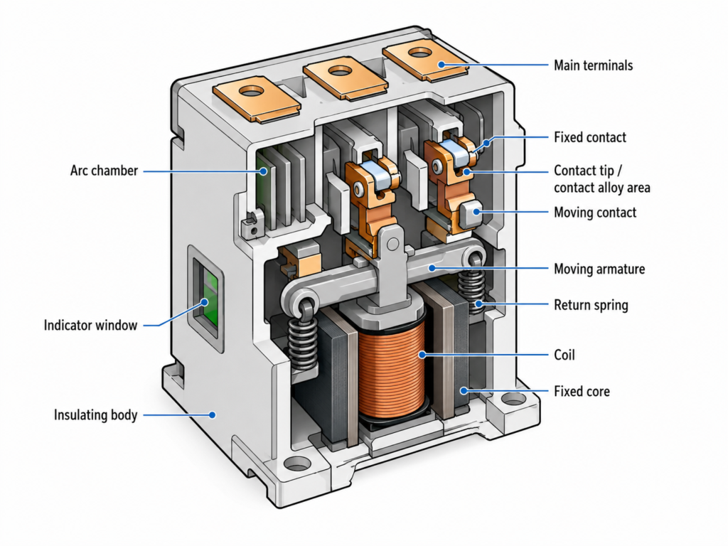
Main Parts of a Contactor
A contactor usually contains these parts:
Coil
Fixed magnetic core
Moving magnetic core or armature
Main power contacts
Auxiliary contacts
Arc chamber
Return spring
Insulation body
Power terminals
Control terminals
Each part has an important job.
The Coil
The coil is the control part of the contactor.
When voltage is applied to the coil, it creates the magnetic field that pulls the contactor closed.
Common contactor coil voltages include:
24 V DC
24 V AC
110 V AC
230 V AC
400 V AC
The coil voltage must match the control circuit voltage.
This is very important.
A contactor can have a 24 V DC coil but switch a 400 V AC motor. The coil voltage and the motor voltage do not have to be the same.
The coil belongs to the control circuit.
The main contacts belong to the power circuit.
These are separate things.
Main Power Contacts
The main power contacts are the contacts that carry motor current.
For a three-phase motor, a contactor usually has three main contacts:
L1 to T1
L2 to T2
L3 to T3
Each phase passes through one main contact.
When the contactor closes, all three phases are connected to the motor.
When the contactor opens, all three phases are disconnected.
These main contacts must be strong enough to handle the motor current.
Why Contactor Contacts Are Bigger Than Relay Contacts
When a contact opens or closes under load, an electric arc can appear.
An arc is a small electrical discharge between the contacts.
This arc can damage the contact surface.
The higher the current, the stronger the arc can be.
Because contactors switch higher currents, their contacts are larger and stronger than normal relay contacts.
The contact material is also important. Many contactor contacts use silver-based alloys because they handle arcing better and last longer.
Arc Chamber
A contactor often includes an arc chamber.
The arc chamber helps control and extinguish the electric arc that appears when the contacts open.
This helps protect the contactor and increases contact life.
Without proper arc control, the contacts would burn much faster.
This is one reason why contactors are physically larger than small relays.
They need space for stronger contacts, bigger magnetic parts, and arc protection.
Double-Break Contacts
Many contactors use a double-break contact design.
This means the circuit is opened at two points instead of only one.
Why is this useful?
Because it helps break the current more safely and reduces arcing stress on each contact point.
In simple terms, instead of one contact doing all the switching work, the load is broken at two contact points.
This improves reliability when switching motor loads.
Auxiliary Contacts
Contactors often have auxiliary contacts.
These are smaller contacts used in the control circuit, not the main motor power circuit.
Auxiliary contacts are used for:
Self-holding circuits
Interlocks
PLC feedback
Signal lamps
Alarm circuits
Control logic
Start/stop circuits
For example, when a contactor energizes, an auxiliary contact can send a signal to the PLC saying:
“The contactor is on.”
Or it can keep the contactor energized after the operator releases the start button. This is called a holding circuit or seal-in circuit.
Auxiliary contacts are usually rated for much lower current than the main contacts because they are used only in control circuits.
Contactor Ratings
Contactors are selected based on the load they need to switch.
Important ratings include:
Motor power rating
Rated operational current
Rated voltage
Coil voltage
Utilization category
Number of poles
Auxiliary contact configuration
Electrical life
Mechanical life
The motor power rating may be given in kW or horsepower.
For example, one contactor may be suitable for a small 5.5 kW motor, while another may be designed for much larger motors.
The larger the motor, the larger the contactor usually needs to be.
Electrical Life and Mechanical Life
Contactors have two important life ratings:
Mechanical life
Electrical life
Mechanical life means how many times the contactor can physically open and close without considering electrical load.
Electrical life means how many times it can switch the load current before the contacts wear out.
Electrical life is usually lower than mechanical life because switching current causes arcing and contact wear.
For example, a contactor may be mechanically capable of millions of operations, but its electrical life depends on the load type and current.
A contactor switching a lightly loaded circuit may last longer than one switching a heavy motor load many times per hour.
Why Load Type Matters
Not all loads are the same.
Switching a heater is not the same as switching a motor.
Motors create high starting current and inductive switching stress. This makes them harder on contacts.
That is why contactors have different application categories.
For example, a contactor used for resistive loads may not be suitable for frequent motor starting.
When selecting a contactor, you should always check the correct rating for the application, not just the current number on the front.
Coil Voltage and Power Voltage Are Independent
This is an important point for beginners.
The coil voltage does not need to match the motor voltage.
For example, you can have:
24 V DC control circuit
24 V DC contactor coil
400 V AC three-phase motor circuit
The PLC or control circuit energizes the 24 V DC coil.
The contactor then switches the 400 V AC motor power.
This separation makes industrial control safer and easier to design.
The control circuit can use a lower voltage, while the contactor handles the high-power motor circuit.
Example: PLC Controlling a Motor Contactor
Here is a simple example.
A PLC output is connected to a 24 V DC contactor coil.
The contactor main contacts are connected to a three-phase motor.
When the PLC output turns on, the contactor coil energizes.
The main contacts close.
Three-phase power reaches the motor.
The motor starts.
When the PLC output turns off, the coil de-energizes.
The contacts open.
The motor stops.
This is one of the most common control methods in industrial automation.
Common Contactor Applications
Contactors are used in many systems, such as:
Direct-on-line motor starters
Star-delta starters
Forward/reverse motor starters
Pump control panels
Fan control panels
Compressor control systems
Conveyor systems
Heating systems
Lighting control panels
Machine control circuits
In motor control, contactors are often combined with overload relays to protect the motor from overload conditions.
The contactor switches the motor.
The overload relay protects the motor.
Final Thoughts
A contactor is basically a heavy-duty electrically operated switch.
It works like a relay, but it is designed for higher power loads, especially motors.
The coil controls the contactor.
The main contacts switch the load.
The auxiliary contacts help with automation logic.
The arc chamber protects the contacts during switching.
Contactors are essential in industrial automation because they allow PLCs, push buttons, relays, and control circuits to safely switch larger electrical loads.
For anyone learning motor control, electrical panels, PLCs, or industrial automation, understanding contactors is very important.
In simple words:
A relay is for smaller control jobs. A contactor is for switching real power.