Thermal overload relays are simple devices.
That is the nice part.
But when a motor keeps tripping, refuses to start, or randomly stops in the middle of production, that “simple” overload relay suddenly becomes the main suspect. Sometimes it really is faulty. Many times it is only doing its job and protecting the motor from a real problem.
That is the important thing to remember.
A tripped thermal overload relay is not always the fault. It may be the warning.
What Does a Thermal Overload Relay Do?
A thermal overload relay protects an electric motor from overload current.
It monitors the current going to the motor. If the motor draws too much current for too long, the relay trips. When it trips, it normally opens a normally closed auxiliary contact in the contactor control circuit. This de-energizes the contactor coil and stops the motor.
So the overload relay usually does not switch the main motor power directly.
The contactor switches the motor.
The overload relay trips the contactor.
Small difference, but important.
Common Symptoms of Thermal Overload Relay Problems
Thermal overload relay faults, or overload-related motor faults, usually show up like this:
- Motor does not start
- Contactor pulls in, then drops out
- Motor starts but trips after a short time
- Motor runs for a few minutes, then overload trips
- Overload relay trips immediately
- Overload relay will not reset
- Motor hums but does not rotate
- One phase current is much higher than the others
- Control circuit has no voltage after overload contact
- Fault lamp stays on
- PLC shows motor overload fault
- Relay trips even when motor current looks normal
The last one is the tricky one. If the current is actually normal but the overload trips, then you may have a bad overload relay, wrong setting, high ambient temperature, poor connection, or mechanical problem affecting the relay.
But first — measure.
Guessing gets expensive.
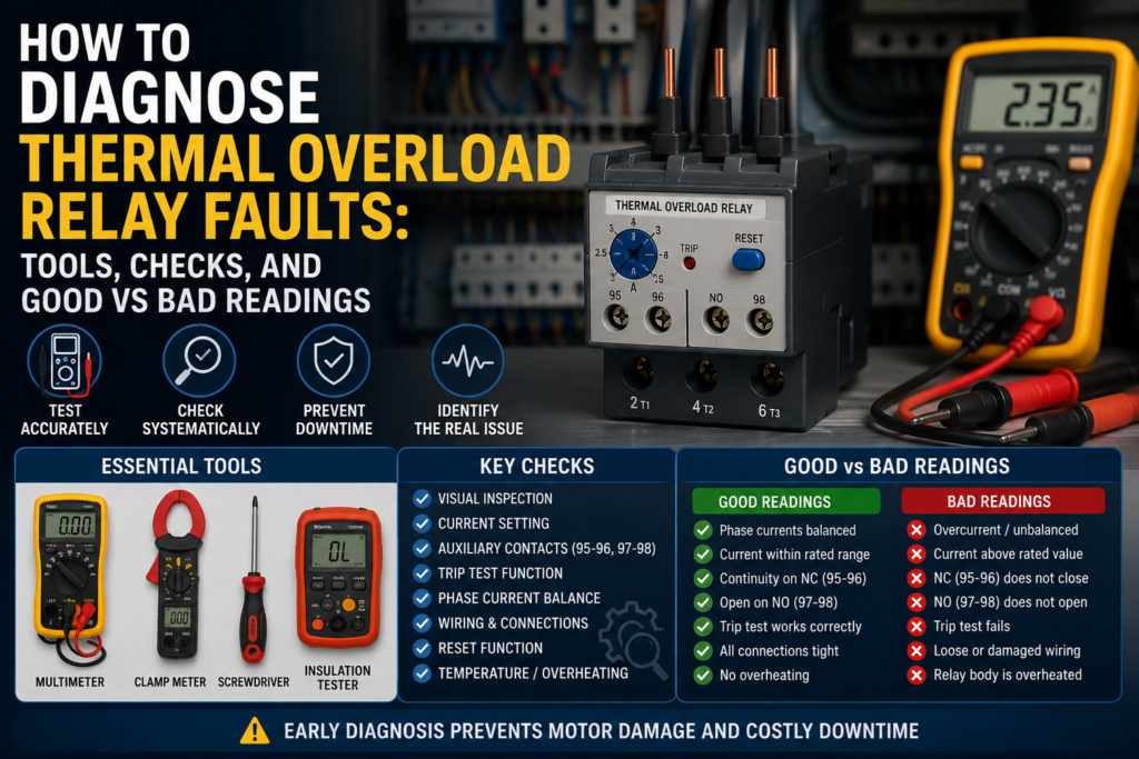
Tools Needed for Diagnosis
You can diagnose most thermal overload relay problems with basic electrical tools.
Useful tools include:
- Digital multimeter
- Clamp meter
- Screwdriver set
- Wiring diagram or motor starter schematic
- Motor nameplate data
- Insulation resistance tester
- Phase sequence tester, optional
- Thermal camera, optional but useful
- Contact cleaner
- Known-good spare overload relay, if available
- PLC online monitor, if overload feedback is wired to PLC
- Current transformer information, if CTs are used
The most important tools are the multimeter and clamp meter.
The multimeter checks the control circuit, contacts, supply voltage, and continuity. The clamp meter tells you what current the motor is really drawing.
And with overload relays, real motor current is the truth teller.
Safety First
Before testing, remember that motor starters contain dangerous voltage.
You may have three-phase power, control voltage, contactor coils, rotating motor shafts, and moving machine parts. Lockout/tagout should be used when working on disconnected circuits. Live testing should only be done by someone qualified and with proper precautions.
Also, do not reset an overload relay again and again without finding the cause.
That is not troubleshooting. That is bullying the motor until it burns.
Step 1: Check the Motor Nameplate Current
Start with the motor nameplate.
Find the rated current. It may be marked as:
- In
- FLA
- Rated current
- Nominal current
- A
For example, a motor nameplate may show 4.8 A at 400 V.
The overload relay current dial should normally be set according to this value, depending on the motor starter design and local standards.
Good condition:
| Check | Good Result |
|---|---|
| Motor nameplate current | Clearly readable |
| Overload relay range | Includes motor rated current |
| Current dial setting | Matches motor rated current |
| Voltage connection | Matches actual supply voltage |
Bad condition:
| Problem | Why It Matters |
| Relay range too small | Nuisance tripping |
| Relay range too large | Poor motor protection |
| Dial set too low | Trips during normal load |
| Dial set too high | Motor may overheat before trip |
| Wrong motor voltage connection | Current may be higher than expected |
If the motor current is 6.2 A and the overload relay range is 2.5–4 A, that is wrong.
If the motor current is 3 A and someone installed a 10–16 A overload relay, that is also wrong.
Not “close enough.” Wrong.
Step 2: Check the Overload Relay Setting
Look at the small current adjustment dial on the overload relay.
The setting should be compared with the motor nameplate current. Do not just assume it is correct because the machine used to work. Someone may have changed it. Happens more often than it should.
Good setting:
- Relay range matches motor current
- Dial is set near the motor rated current
- Setting is not turned fully up just to avoid trips
- Setting is not below normal motor current
- Reset mode is suitable for the machine
Bad setting:
- Dial set much lower than motor rated current
- Dial set much higher than motor rated current
- Relay current range does not match motor
- Automatic reset selected where manual reset is required
- Setting changed without checking motor current
A wrong setting is one of the easiest faults to find.
And also one of the most embarrassing.
Step 3: Check If the Overload Relay Is Tripped
Most overload relays have a trip indicator or reset button position that shows if the relay has tripped.
Check the relay status.
Good condition:
| State | Meaning |
| Not tripped | Control contact should be in normal state |
| Tripped after overload | Relay reacted to fault |
| Resets after cooling | Thermal mechanism working normally |
Bad condition:
| Symptom | Possible Cause |
| Will not reset | Relay still hot, mechanism damaged, overload still present |
| Trips immediately after reset | Short circuit, phase loss, wrong wiring, faulty relay |
| Reset button feels stuck | Mechanical damage |
| No trip indication but NC contact open | Faulty auxiliary contact or mechanism |
| Relay resets but trips again quickly | Real motor overload likely |
After a real overload trip, the relay may need time to cool before it can reset. That is normal.
But if it cannot reset after cooling, suspect mechanical failure or a damaged overload relay.
Step 4: Check the Auxiliary Contacts
Thermal overload relays normally have at least two auxiliary contacts:
- NC contact for stopping the contactor
- NO contact for overload fault indication
Common terminal numbers are often:
- 95–96 = normally closed overload contact
- 97–98 = normally open fault contact
Always check the actual device marking.
With power off, use a multimeter in continuity mode.
Good readings when relay is not tripped:
| Contact | Expected Reading |
| 95–96 NC | Closed / low resistance |
| 97–98 NO | Open circuit / OL |
Good readings when relay is tripped:
| Contact | Expected Reading |
| 95–96 NC | Open circuit / OL |
| 97–98 NO | Closed / low resistance |
Bad readings:
| Reading | Possible Fault |
| 95–96 open when relay is reset | Faulty overload contact or not reset properly |
| 97–98 closed when relay is reset | Faulty contact or trip mechanism stuck |
| Contacts do not change with test button | Mechanical fault or damaged auxiliary contacts |
| High resistance across closed contact | Worn, dirty, or burned contact |
| Intermittent reading | Loose terminal or damaged internal contact |
A closed auxiliary contact should have very low resistance. Usually close to 0 Ω or at least well under 1–2 Ω, depending on meter leads and contact condition.
If you see unstable readings, high resistance, or open circuit when it should be closed, the contact may be faulty.
Step 5: Check Control Voltage Through the Overload Contact
Now check the control circuit.
The overload NC contact is usually wired in series with the contactor coil. If this contact is open, the contactor will not energize.
With the control circuit powered, measure voltage before and after the overload NC contact.
Good readings:
| Test Point | Good Reading |
| Control voltage before overload NC | Correct control voltage |
| Control voltage after overload NC when reset | Same control voltage |
| Voltage after overload NC when tripped | 0 V or missing control voltage |
Examples:
For a 24 V DC control circuit, you should usually see around 24 V DC before and after the closed overload NC contact.
For a 230 V AC control circuit, you should usually see around 230 V AC before and after the closed overload NC contact.
Bad readings:
| Reading | Possible Cause |
| Voltage before contact but not after when reset | NC contact open or bad terminal |
| Voltage missing before contact | Fault is upstream in control circuit |
| Voltage after contact but contactor still off | Fault after overload, coil issue, stop circuit problem |
| Voltage drops across closed contact | High resistance contact or loose terminal |
A closed overload contact should not create a noticeable voltage drop.
If you measure a voltage drop across a closed NC contact, that is suspicious. It may mean a bad contact or loose connection.
Step 6: Test the Trip Button
Most overload relays have a test button.
Pressing the test button should simulate a trip and change the auxiliary contacts.
Good result:
- NC contact opens
- NO contact closes
- Contactor drops out
- Fault lamp or PLC input activates
- Relay can be reset afterward
Bad result:
- Nothing changes
- Contactor stays energized
- Fault indication does not work
- Relay cannot reset after test
- Test button feels jammed
This test confirms the control circuit reaction. It does not prove the thermal part trips at the correct current, but it is still useful.
If the test button opens the NC contact and the contactor drops out, the control wiring is probably correct.
Step 7: Measure Motor Current With a Clamp Meter
This is the big one.
Clamp each motor phase one at a time while the motor is running.
Compare the measured current with the motor nameplate current and overload setting.
Good readings:
| Condition | Good Reading |
| Normal running current | At or below motor rated current |
| Three-phase current balance | Phases close to each other |
| No-load motor | Much lower than rated current |
| Loaded motor | Below or near rated current, depending on load |
Bad readings:
| Reading | Possible Cause |
| Current above rated value | Mechanical overload, wrong motor, low voltage |
| One phase much higher | Phase imbalance, motor winding issue, supply problem |
| One phase zero | Lost phase, blown fuse, bad contactor pole, broken wire |
| All phases very high | Jammed load, locked rotor, wrong wiring |
| Current high but motor slow | Mechanical load, low voltage, bearing problem |
| Current normal but overload trips | Wrong setting, faulty overload, high ambient temperature |
As a rough guide, phase currents should usually be reasonably balanced. A small difference is normal. A large difference is not.
If one phase is much higher or much lower than the others, do not ignore it.
That is often where the real fault is hiding.
Step 8: Compare Current to Overload Setting
Let’s say the motor nameplate current is 5.5 A.
If the motor is running at 5.0–5.4 A, that is usually okay.
If it is running at 6.5 A continuously, the overload relay may trip because the motor is overloaded.
If the overload relay is set to 4.5 A, it may trip even though the motor is not overloaded according to its nameplate.
Good comparison:
| Motor Rated Current | Actual Current | Overload Setting | Result |
| 5.5 A | 5.1 A | 5.5 A | Good |
| 5.5 A | 6.8 A | 5.5 A | Motor overload likely |
| 5.5 A | 4.8 A | 4.0 A | Setting too low |
| 5.5 A | 5.2 A | 8.0 A | Poor protection |
Do not raise the overload setting above the proper value just to stop nuisance trips.
Find out why it is tripping.
Yes, slower. But cheaper than a burned motor.
Step 9: Check for Phase Loss
Phase loss is a common reason for overload trips.
A three-phase motor that loses one phase may continue running, but the current in the remaining phases can increase heavily. This creates heat and can quickly damage the motor.
Check voltage phase-to-phase at the motor starter output and motor terminals.
Typical good readings in a 400 V system:
| Measurement | Good Reading |
| L1–L2 | Around 400 V AC |
| L2–L3 | Around 400 V AC |
| L1–L3 | Around 400 V AC |
Bad readings:
| Measurement | Possible Cause |
| One phase-to-phase voltage missing | Blown fuse, bad breaker pole, contactor fault |
| Voltage good at supply but missing after contactor | Burned contactor contact |
| Voltage good at starter but missing at motor | Cable fault |
| One motor phase current is 0 A | Open phase or broken connection |
Phase loss can be caused by:
- Blown fuse
- Bad contactor pole
- Loose terminal
- Damaged cable
- Broken motor winding
- Faulty breaker
- Bad connection in junction box
If overload relay trips and one phase current is missing, do not just reset it. Find the lost phase.
Step 10: Check Contactor Contacts
A bad contactor can cause overload trips.
If one main contact is burned, loose, or high resistance, the motor may receive poor voltage on one phase. This can create current imbalance and overheating.
Check voltage across each contactor pole when closed.
Good condition:
- Very low voltage drop across each closed contact
- Similar voltage on all three output phases
- No overheating at terminals
- No visible burning
Bad condition:
- High voltage drop across one contact
- One phase voltage lower after contactor
- Burned or pitted contacts
- Terminal discoloration
- Hot contactor pole
- Motor current imbalance
A thermal camera can be very helpful here. A hot terminal or contactor pole often tells the story before the meter does.
Not always. But often.
Step 11: Check Terminal Tightness and Heating
Loose terminals create heat.
Heat affects overload relays. It also damages cables, contactors, and motor starters.
Inspect all terminals:
- Supply terminals
- Contactor terminals
- Overload relay terminals
- Motor output terminals
- Control circuit terminals
- Motor junction box terminals
Good condition:
- Terminals tight
- No discoloration
- No melted plastic
- No burned smell
- Similar temperature between phases
- No damaged wire insulation
Bad condition:
- Loose terminal
- Brown or black discoloration
- Melted insulation
- Burned smell
- One phase terminal much hotter
- Screw damaged or stripped
A loose terminal can cause voltage drop, phase imbalance, and overload trips.
It can also become a fire risk.
Not a small thing.
Step 12: Check the Motor Mechanically
If the motor current is high, the overload relay may be doing exactly what it should.
Check the mechanical load.
Possible mechanical causes include:
- Jammed conveyor
- Blocked pump impeller
- Fan obstruction
- Gearbox problem
- Worn bearings
- Misalignment
- Too much belt tension
- Product jam
- Machine running overloaded
- Dirty filter or blocked airflow
Good mechanical condition:
- Motor turns freely when safe to check
- Load moves normally
- Bearings sound normal
- No abnormal vibration
- Current drops when load is reduced
Bad mechanical condition:
- Motor difficult to turn
- Pump blocked
- Conveyor jammed
- Gearbox hot
- Bearing noisy
- Belt too tight
- Current rises with load
- Motor trips only under production load
If the motor runs fine uncoupled but trips under load, the problem is probably not the overload relay.
The machine is asking too much from the motor.
Step 13: Check Motor Insulation
If a motor repeatedly trips overload or draws abnormal current, check insulation resistance.
Use an insulation resistance tester only with the motor disconnected and isolated from drives, electronics, and control devices.
Good insulation readings depend on motor voltage, size, environment, and standards, but as a practical maintenance rule:
| Test | Good Sign |
| Phase to earth | High resistance, typically many megaohms |
| Phase to phase | High resistance and balanced |
| Reading trend | Stable over time |
Bad signs:
| Reading | Possible Cause |
| Very low resistance to earth | Insulation failure, moisture, winding damage |
| One phase much lower | Winding insulation problem |
| Reading changes with temperature/moisture | Moisture ingress or damaged insulation |
| Insulation below site limit | Motor needs drying, repair, or replacement |
A common quick rule used in many workshops is that readings should be in the megaohm range, not kiloohms. For critical motors, follow your company standard or motor manufacturer requirements.
Do not perform insulation tests through VFDs, PLC outputs, soft starters, or electronic protection devices. Disconnect properly first.
Step 14: Check Reset Mode
Thermal overload relays may have manual or automatic reset.
Manual reset is usually safer for machinery because someone must inspect and reset the fault.
Automatic reset can restart a motor unexpectedly if the control circuit still commands it to run. That can be dangerous.
Good setup:
| Application | Preferred Reset |
| Most machinery | Manual reset |
| Safety-sensitive equipment | Manual reset |
| Remote special systems | Automatic only if risk assessed |
| Fault investigation | Manual reset preferred |
Bad setup:
- Automatic reset used on machinery where unexpected restart is dangerous
- Reset mode changed without checking safety
- Overload resets and motor restarts repeatedly
- Fault is hidden because relay resets by itself
If the motor keeps stopping and restarting, check whether automatic reset is enabled. That can make the fault harder to notice and more dangerous.
Step 15: Check Overload Relay Temperature and Environment
Thermal overload relays work with heat, so the surrounding temperature matters.
If the control panel is very hot, the relay may trip earlier than expected. Some relays have compensation, but heat can still affect performance.
Check for:
- Hot control cabinet
- Poor ventilation
- Overload relay mounted near heat source
- Loose terminals generating heat
- Contactor heat
- High ambient temperature
- Dust blocking ventilation
Good condition:
- Cabinet temperature reasonable
- No local overheating
- Terminals cool and tight
- Relay not installed near excessive heat
- Motor current matches setting
Bad condition:
- Relay body very hot
- One terminal hotter than others
- Cabinet overheating
- Relay trips at normal motor current
- Heat damage visible
If current is normal but the overload trips in a hot panel, temperature may be contributing.
A thermal camera is very useful here. It quickly shows hot spots that your eyes miss.
Step 16: Check Current Transformers on Large Motors
For larger motors, the overload relay may be connected through current transformers.
In that case, check:
- CT ratio
- CT wiring
- Correct secondary current
- Correct overload relay setting
- Loose CT secondary terminals
- Open CT secondary circuit
- Wrong phase routing
- Incorrect CT orientation, if relevant to the system
Good condition:
- CT ratio matches design
- Secondary current proportional to motor current
- Overload relay setting calculated correctly
- CT wiring secure
- All three phases balanced
Bad condition:
- Wrong CT ratio
- CT secondary open
- One CT not wired
- Incorrect setting after CT replacement
- One phase current missing at relay
- Relay trips incorrectly or never trips
CT circuits must be handled carefully. An open CT secondary can create dangerous voltage. Use proper procedures.
No guessing here.
Good and Bad Readings Summary
Here is a practical quick-reference table.
| Check | Good Reading / Condition | Bad Reading / Condition |
| Motor current | At or below nameplate current | Above rated current continuously |
| Phase current balance | Similar currents on all phases | One phase much higher/lower |
| Phase voltage | Balanced phase-to-phase voltage | Missing or low phase |
| Overload setting | Matches motor rated current | Too low or too high |
| 95–96 NC reset | Closed / low resistance | Open when reset |
| 95–96 NC tripped | Open circuit | Still closed when tripped |
| 97–98 NO reset | Open circuit | Closed when reset |
| 97–98 NO tripped | Closed / low resistance | Still open when tripped |
| Voltage across closed NC contact | Almost 0 V drop | Noticeable voltage drop |
| Control voltage after NC contact | Same as before contact when reset | Missing voltage when reset |
| Contactor voltage drop | Very low across closed contacts | High drop on one pole |
| Motor insulation | High resistance in megaohms | Low or unbalanced resistance |
| Terminals | Tight and cool | Loose, hot, discolored |
| Reset | Resets after cooling | Will not reset or trips immediately |
Common Faults and Likely Causes
| Symptom | Likely Cause |
| Motor will not start | Overload NC contact open, relay tripped, control voltage missing |
| Contactor drops out | Overload tripped, bad NC contact, control circuit fault |
| Trips after minutes | Real overload, wrong setting, overheating, mechanical load |
| Trips immediately | Severe overload, phase loss, locked rotor, faulty relay |
| Trips at normal current | Wrong setting, bad relay, hot cabinet, poor terminal |
| Cannot reset | Relay still hot, mechanism damaged, trip still active |
| Fault lamp always on | NO contact stuck closed, relay tripped, wiring fault |
| No fault signal after trip | NO contact faulty or not wired correctly |
| One phase current high | Phase imbalance, motor fault, contactor issue |
| One phase current zero | Lost phase, fuse, cable, contactor pole, winding fault |
| Motor hums | Phase loss, locked rotor, low voltage |
| Overload setting keeps being increased | Real fault being ignored |
When the Overload Relay Is Actually Faulty
Thermal overload relays can fail, but they should not be blamed first.
Possible overload relay faults include:
- Auxiliary contact stuck open
- Auxiliary contact stuck closed
- Trip mechanism jammed
- Current dial damaged
- Relay will not reset
- Relay trips at normal current
- Heat damage
- Burned terminals
- Mechanical damage
- Internal bimetal fatigue after long service
The relay is more likely faulty if:
- Motor current is normal
- Phase currents are balanced
- Voltage is correct
- Mechanical load is normal
- Current setting is correct
- Cabinet temperature is normal
- Relay still trips repeatedly
At that point, replacing the overload relay is reasonable.
But replacing it before checking current is just gambling with a screwdriver.
Final Troubleshooting Checklist
Use this checklist when diagnosing thermal overload relay faults:
- Check if the overload relay is tripped.
- Read the motor nameplate current.
- Confirm overload relay current range.
- Check the current dial setting.
- Test NC and NO auxiliary contacts.
- Measure control voltage before and after the NC contact.
- Press the test button and confirm contact operation.
- Measure motor current on all phases.
- Compare motor current with the overload setting.
- Check phase-to-phase voltage.
- Look for phase loss or imbalance.
- Inspect contactor main contacts.
- Check terminal tightness and heating.
- Inspect mechanical load.
- Check motor insulation if needed.
- Verify manual or automatic reset mode.
- Check cabinet temperature and heat sources.
- Check CT wiring and ratios on large motors.
- Replace the overload relay only after confirming the basics.
Final Thoughts
A thermal overload relay is not complicated, but it is very important.
It protects a motor from running too hot for too long. When current rises above the set value, the relay heats internally, trips, opens the control circuit, and drops out the contactor. The motor stops before the damage becomes worse.
When diagnosing faults, do not start by turning the current dial higher.
Start with the motor nameplate. Check the setting. Measure the real current. Compare all three phases. Check the auxiliary contacts. Follow the control voltage through the relay. Look for mechanical overload, phase loss, bad contactor poles, loose terminals, and overheating.
Most overload trips are not mysterious.
Sometimes the relay is faulty. But often, it is just the messenger — and the message is: the motor is working harder than it should.