A direct-on-line starter, usually shortened to DOL starter, is one of the simplest ways to start a three-phase induction motor.
When the START button is pressed, the motor is connected directly to the three-phase supply and receives full line voltage. This makes the circuit straightforward and reliable, although the high starting current means DOL starting is generally better suited to smaller motors or installations where the supply can tolerate the inrush.
The circuit contains two sections:
- Power circuit
- Control circuit
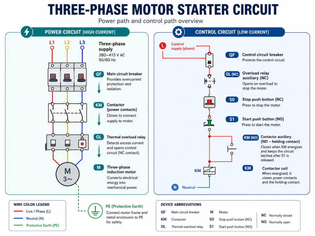
Power Circuit
The three phases—R, S and T—first pass through a three-pole circuit breaker or motor-protection device.
They then connect to the main terminals of contactor K1:
- R → 1/L1
- S → 3/L2
- T → 5/L3
The contactor outputs feed the thermal overload relay, which then connects to motor M1.
When K1 is de-energized, its main contacts remain open and the motor receives no power. When K1 energizes, all three contacts close and full supply voltage reaches the motor.
Control Circuit
The control phase passes through:
- Control circuit breaker or fuse F2
- Overload relay NC contact 95–96
- Normally closed STOP button S1
- Normally open START button S2
- Contactor coil K1
The other side of the contactor coil, A2, connects to neutral or the correct return conductor for the coil voltage.
How the DOL Starter Operates
When the START button is pressed, current flows through the healthy overload contact, STOP button and START button to coil K1.
The coil energizes and closes:
- The three main power contacts
- Auxiliary contact K1, usually numbered 13–14
The auxiliary contact is connected in parallel with the START button. Once it closes, it creates a holding—or seal-in—circuit. This keeps the contactor energized after the START button is released.
Pressing the STOP button opens the control circuit. The coil de-energizes, the contactor opens and the motor stops.
If the thermal overload relay trips, contact 95–96 also opens and disconnects the contactor coil.
Component Labels
The same designation must identify every part belonging to one device.
For example, if the contactor is labelled K1, then its:
- Coil
- Main contacts
- Auxiliary contacts
should all carry the K1 reference.
Consistent labels make the connection between power and control diagrams much easier to follow.