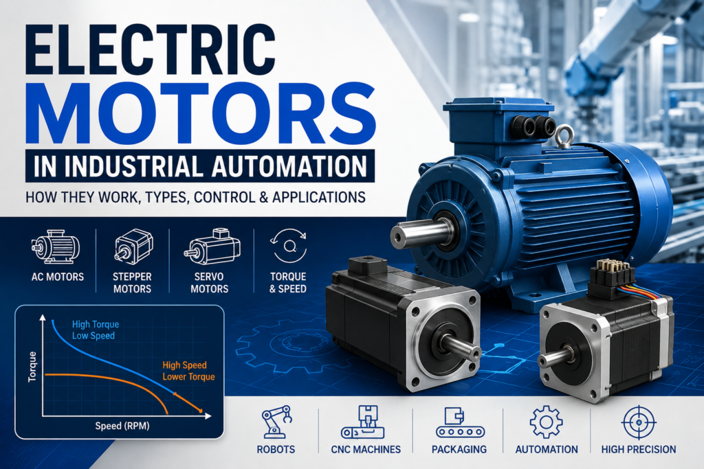
Electric motors are one of the most important parts of industrial automation.
They are used to create movement in machines. You can find them in conveyors, pumps, fans, compressors, machine tools, mixers, extruders, and many other factory systems.
In simple words, an electric motor converts electrical energy into mechanical movement.
That movement can be rotary, like a spinning shaft, or it can be converted into linear movement using mechanical parts such as gears, pulleys, belts, ball screws, and guide rails.
Are Electric Motors Actuators?
Technically, yes.
An actuator is a device that creates motion or force, and electric motors clearly do that.
However, in industrial automation, people often separate electric motors from smaller actuators.
For example, when someone says “actuator,” they may be talking about a pneumatic cylinder, solenoid, small linear actuator, or valve actuator.
But when they say “motor,” they usually mean a larger device used to produce mechanical power.
So, for practical industrial automation learning, it is useful to treat electric motors as their own main category.
How Electric Motors Work
Most electric motors work using magnetic fields.
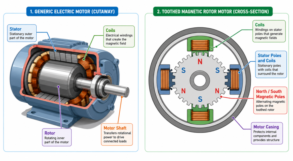
Inside a motor, there are two main parts:
Stator — the stationary part of the motor
Rotor — the rotating part of the motor
The stator creates a magnetic field. The rotor reacts to this magnetic field. This interaction creates torque, which makes the rotor turn.
That rotation is transferred to the motor shaft, and the shaft then drives the machine.
This basic idea applies to many types of motors, including AC motors, DC motors, stepper motors, and servomotors.
DC Motors
A DC motor uses direct current.
In many DC motors, current flows through coils in the rotor. These coils are placed inside the magnetic field of the stator. The stator may use permanent magnets or electromagnets.
When current flows through the rotor coils, it creates a magnetic field. This magnetic field interacts with the stator magnetic field, and the rotor starts to turn.
To reverse the direction of a DC motor, you usually change the polarity of either the field winding or the armature winding.
But not both at the same time.
If both are reversed, the direction may stay the same.
DC motors are easy to understand and control, but in modern industrial automation they are less common than AC induction motors for many general machine applications.
AC Induction Motors
The AC induction motor is one of the most common motors in industry.
It is widely used because it is reliable, efficient, strong, and requires relatively little maintenance.
Common AC induction motor applications include:
Conveyors
Pumps
Fans
Compressors
Machine tools
Extruders
Mixers
Industrial production machines
In a three-phase AC induction motor, the stator has three-phase windings. When three-phase AC voltage is applied, these windings create a rotating magnetic field.
This rotating magnetic field induces current in the rotor.
The rotor then creates its own magnetic field, and the interaction between the stator field and rotor field makes the rotor turn.
This is why it is called an induction motor. The rotor current is induced by the magnetic field from the stator.
How to Reverse a Three-Phase Motor
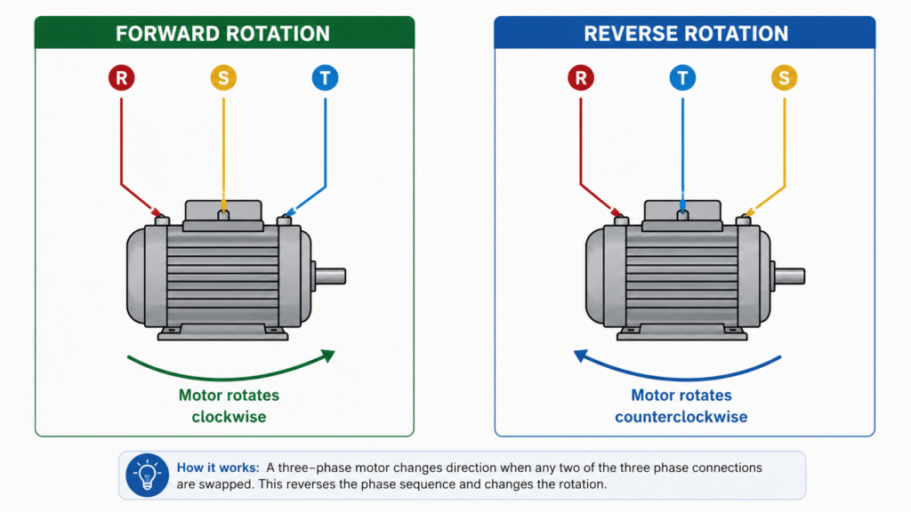
To reverse the direction of a three-phase induction motor, you swap any two of the three motor supply phases.
For example, if the motor has phases L1, L2, and L3, swapping L1 and L2 will reverse the rotation direction.
Important point:
Swapping all three phases does not change the rotation direction.
Only two phases need to be swapped.
Stepper Motors
A stepper motor is a motor that moves in small, controlled steps.
Instead of rotating smoothly like a normal motor, it moves one step at a time. Each step is a small angle of rotation.
For example, one step may be:
2 degrees
1 degree
Less than 1 degree
The exact step angle depends on the motor design.
Stepper motors are controlled by electrical pulses. Each pulse moves the motor by one step.
So, if the controller sends 100 pulses, the motor moves 100 steps.
The speed of the stepper motor depends on how fast the pulses are sent.
Why Stepper Motors Are Useful
Stepper motors are useful because they can control position without always needing an encoder.
They are often used in open-loop control systems.
This means the controller sends a certain number of pulses and assumes the motor has moved to the correct position.
Stepper motors are commonly used in:
3D printers
CNC machines
Small positioning systems
Packaging machines
Lab equipment
Small automation machines
They are good for low to medium power applications where accurate position control is needed.
Basic Stepper Motor Control Signals
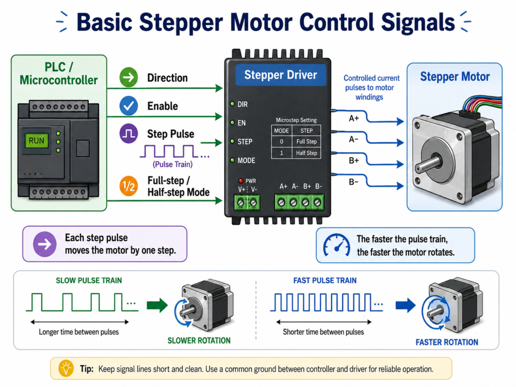
A stepper motor usually needs a driver.
The controller, such as a PLC or microcontroller, sends control signals to the stepper driver. The driver then sends the correct current pulses to the motor windings.
Common stepper control signals include:
Direction signal
Enable signal
Step pulse signal
Full-step or half-step mode signal
Each step pulse moves the motor by one step.
The faster the pulse train, the faster the motor rotates.
Stepper Motor Limitation
A stepper motor can lose steps if it is overloaded or accelerated too quickly.
If the load is too heavy, the motor may not reach the expected position, even though the controller continues sending pulses.
That is why stepper motors must be sized correctly for the application.
Servomotors
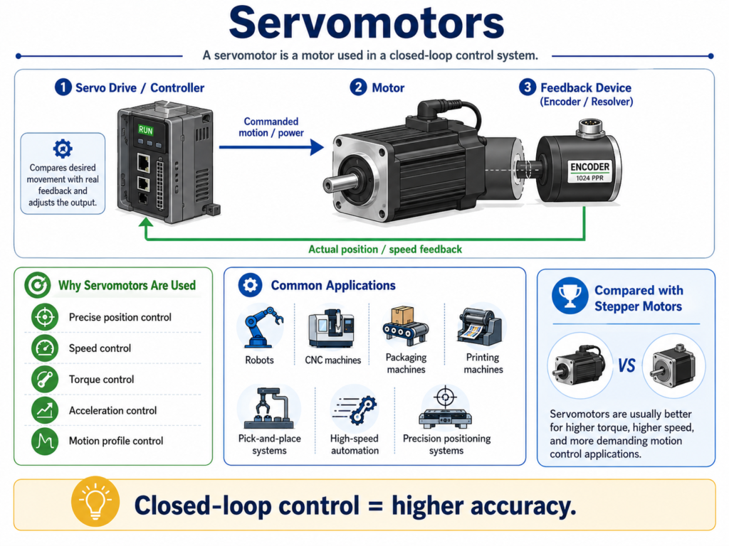
A servomotor is not just one special type of motor.
The word “servo” usually means a motor used in a closed-loop control system.
A servomotor system normally includes:
A motor
A feedback device
A servo drive or controller
The feedback device is usually an encoder or resolver. It tells the controller the actual position or speed of the motor.
The controller compares the desired movement with the real feedback and adjusts the motor output.
This makes servomotors very accurate.
Why Servomotors Are Used
Servomotors are used when you need precise control of:
Position
Speed
Torque
Acceleration
Motion profile
They are commonly used in:
Robots
CNC machines
Packaging machines
Printing machines
Pick-and-place systems
High-speed automation
Precision positioning systems
Compared with stepper motors, servomotors are usually better for higher torque, higher speed, and more demanding motion control applications.
Open-Loop vs Closed-Loop
A stepper motor often works in open-loop mode.
The controller sends pulses and expects the motor to follow.
A servomotor works in closed-loop mode.
The controller constantly checks feedback and corrects the motor movement.
That is the main difference.
Open-loop is simpler.
Closed-loop is more accurate and reliable for demanding applications.
Motor Torque and Speed
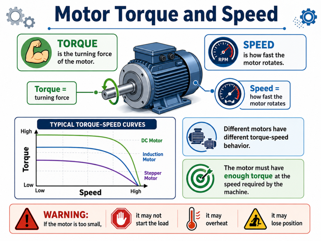
When choosing a motor, it is important to understand torque and speed.
Torque is the turning force of the motor.
Speed is how fast the motor rotates.
Different motors have different torque-speed behavior.
This matters because a motor must have enough torque at the speed required by the machine.
If the motor is too small, it may not start the load, may overheat, or may lose position.
AC Motor Starting Current and Torque
When an AC induction motor starts from standstill, it can draw a very high current.
This is called locked rotor current.
Locked rotor current can be many times higher than the normal full-load current.
For example, some motors can draw 5 to 7 times their full-load current during startup. In some cases, it can be even higher.
At startup, the motor also produces locked rotor torque.
As the motor accelerates, the current and torque change. The motor current usually stays high until the motor reaches most of its rated speed.
This is why large motors often need proper starting methods, such as:
Star-delta starters
Soft starters
Variable Frequency Drives
Reduced voltage starters
A VFD is especially useful because it can control acceleration, reduce mechanical stress, and limit starting current.
Stepper Motor Torque-Speed Curve
Stepper motors also have important torque-speed limits.
A stepper motor can produce good torque at low speeds, but torque usually drops as speed increases.
One important curve is the pull-out torque curve.
This curve shows the maximum torque the stepper motor can provide at different speeds.
If the load requires more torque than the motor can provide, the motor may lose synchronism and miss steps.
Another important value is holding torque.
Holding torque is the torque the motor can produce while stopped, with current applied to the windings.
This is useful when the motor needs to hold a position without moving.
When selecting a stepper motor, the load requirements must stay within the motor’s torque-speed limits.
How Motor Motion Is Used in Machines
The motor shaft usually produces rotary motion.
But machines often need different types of movement.
The motor rotation can be transferred or converted using:
Gears
Belts
Pulleys
Chains
Ball screws
Lead screws
Spindles
Couplings
Guide rails
For example, a motor can rotate a ball screw. The ball screw then converts rotary motion into linear movement.
This is common in CNC machines, linear axes, and automation systems.
So even if the motor rotates, the final machine movement can be linear, rotary, reciprocating, or something more complex.
Motor Control vs Automation Control
It is useful to separate two ideas:
Motor control and automation control.
Motor Control
Motor control focuses on how the motor itself is controlled.
This includes:
Speed control
Torque control
Position control
Acceleration
Deceleration
Closed-loop feedback
VFD or servo drive tuning
For example, a VFD controlling the speed of an AC motor is part of motor control.
A servo drive controlling the exact position of a servomotor is also motor control.
Automation Control
Automation control focuses on the sequence of machine operation.
This includes:
When the motor starts
When the motor stops
Which direction it runs
Which relay or contactor turns on
Which sensor must be active
Which step happens next
How the PLC controls the process
For example, a PLC may decide when to start a conveyor motor based on a sensor signal.
The VFD controls the motor speed, but the PLC controls the process sequence.
Both are important.
Final Thoughts
Electric motors are a major part of industrial automation.
They convert electrical energy into mechanical movement and allow machines to move, pump, cut, rotate, lift, position, and process materials.
The most common motor types include:
DC motors
AC induction motors
Stepper motors
Servomotors
Linear motors
Solenoids
AC induction motors are widely used in industry because they are reliable and require less maintenance.
Stepper motors are useful for simple open-loop positioning.
Servomotors are used when precise closed-loop control is needed.
To understand industrial automation properly, it is important to understand not only how motors work, but also how they are controlled by drives, PLCs, relays, contactors, and feedback devices.
In simple terms:
The motor creates the movement.
The drive controls the motor.
The PLC controls the machine sequence.
Once you understand that relationship, industrial automation starts to make much more sense.