Troubleshooting turns guesswork into measurement, and measurement requires the right instruments used correctly. You do not need an enormous or expensive kit, but you do need a few good tools and the discipline to use each one properly and safely.
| Instrument | What it tells you | Key safety / usage note |
|---|---|---|
| Digital multimeter (DMM) | Voltage, resistance, continuity | Use a meter with an adequate CAT rating for the circuit |
| Clamp meter | Current without breaking the circuit | Essential for motor and load current checks |
| Insulation resistance tester (megohmmeter) | Insulation integrity of motors and cables | Applies high voltage — isolate and discharge first |
| Non-contact voltage tester | Quick presence-of-voltage indication | A screening tool only; never a substitute for a meter |
| Thermal imaging camera | Hot spots from loose or overloaded connections | Finds failing joints before they fail completely |
| Voltage/phase tester | Presence and rotation of phases | Confirms phasing on three-phase work |
| Insulated hand tools, PPE, locks | Safe work on and around energized gear | Never improvise isolation or insulation |
Getting the most from a multimeter
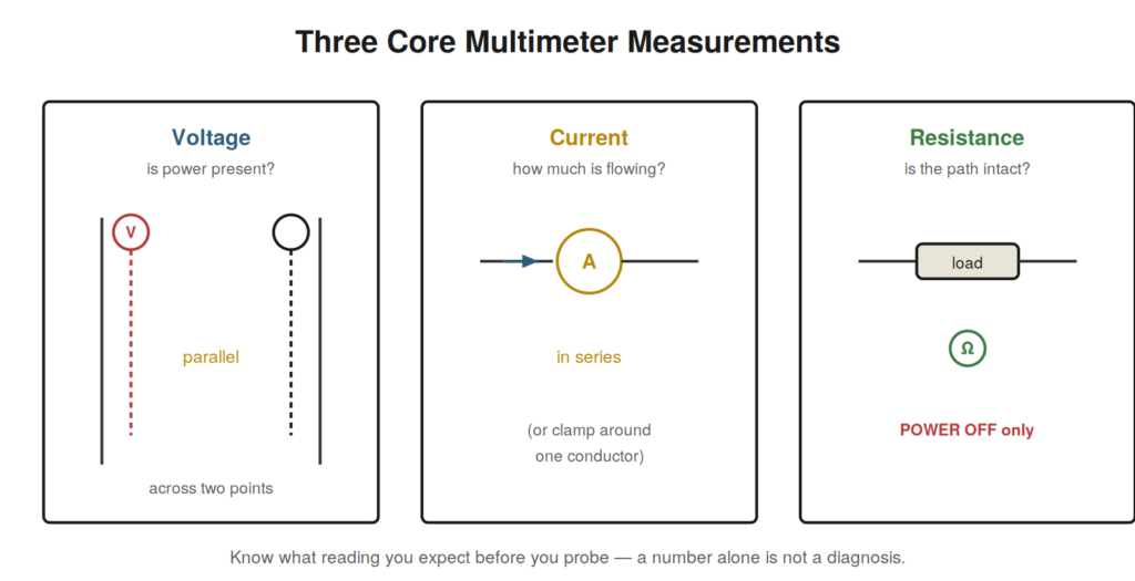
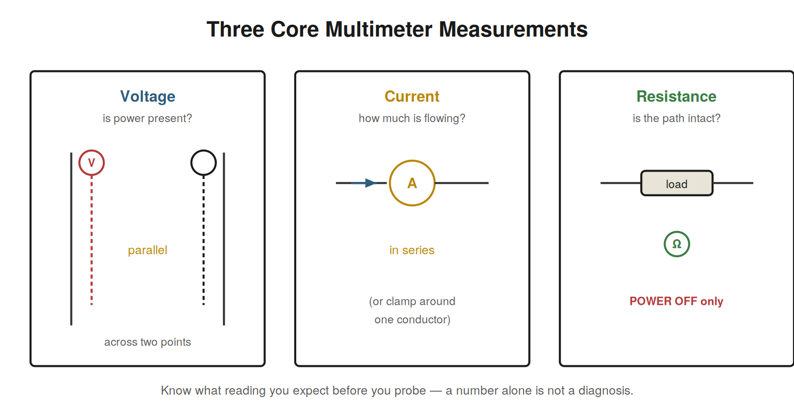
The multimeter is the instrument you will reach for most, and three habits separate reliable measurements from misleading ones. First, always know what value you expect before you place the probes; a reading compared against an expectation is a diagnosis, while a reading alone is just a number. Second, mind your reference point, because a voltage is always measured between two points and metering against the wrong common produces phantom faults. Third, respect the difference between a measurement taken with no load and one taken under load, because a supply can read correctly with nothing drawing from it and collapse the moment a real load connects.
Continuity and resistance measurements demand special care because they must be made on a de-energized circuit. Measuring resistance on a live circuit gives meaningless results and can damage the meter or injure you. The rule is simple and absolute: isolate, prove dead, then measure resistance. And remember that continuity through a conductor proves the conductor is intact, not that it is the right conductor connected to the right place — continuity is necessary but not sufficient.
The clamp meter and what current reveals
Where voltage tells you whether power is present, current tells you whether something is actually working and how hard. The clamp meter reads current by sensing the magnetic field around a conductor, without breaking the circuit, and it opens a dimension of diagnosis that voltage alone cannot reach. A motor’s running current compared against its nameplate reveals whether it is loaded normally, straining, or barely working. A circuit’s current draw shows whether a load is drawing what it should. Because current reflects actual work being done rather than the mere presence of voltage, it catches faults that voltage measurements miss, and learning to reach for it roughly doubles what your meter kit can tell you.
Instruments that find what a meter cannot
Two specialized instruments earn their place for faults a basic meter cannot see. The insulation resistance tester applies a high test voltage to reveal insulation that has degraded — the slow failure behind many motor and cable faults — but because it applies high voltage, the circuit must be isolated and discharged before and after use. The thermal imaging camera reveals heat, and heat is the signature of a failing connection: a loose or corroded joint develops resistance, resistance under current produces heat, and a thermal scan of a panel under load finds these developing faults before they fail outright. Together they shift you from reacting to failures toward catching them as they develop.
A case file: the meter that lied
A technician measures 24 volts at a sensor’s terminals and concludes the power is fine, yet the sensor does not work. The reading was real but misleading, because it was taken with the sensor disconnected — an open-circuit measurement. The supply wire had a corroded joint with high resistance that dropped almost nothing with no current flowing but collapsed the voltage the moment the sensor drew its operating current. Re-measuring with the sensor connected and drawing current revealed only a few volts at the terminals, nowhere near enough. The lesson is that a voltage measured under no load can hide a high-resistance fault that only appears under load, and when a circuit reads good but works badly, you must measure it working, with its real load connected and drawing current. This single habit exposes a whole class of faults that open-circuit measurements miss entirely.
Choosing and trusting a meter
Not all meters are equal, and for industrial work the meter’s safety rating matters as much as its features. Meters carry a category (CAT) rating that reflects the transient energy they can safely handle, and using a meter with an inadequate rating on a high-energy circuit risks the meter failing violently in your hand. A quality meter with an appropriate CAT rating for the circuits you work on, with good leads and proper fusing, is a genuine safety device, not merely a convenience. Beyond safety, a meter you trust is one you have proven — which is the whole point of the live–dead–live habit — because a meter with a dead battery, a blown internal fuse, or a broken lead can read zero on a live circuit and invite a fatal mistake. Trust the meter only after you have proven it, every time it matters.
The thermal camera as a troubleshooting multiplier
Of all the specialized instruments, the thermal imaging camera has perhaps the highest ratio of faults found to effort expended, because it makes visible the heat that failing connections and overloaded components produce. Scanning an energized panel under normal load, the camera reveals hot spots invisible to the eye: a terminal running far hotter than its neighbors, a connection developing resistance, a conductor carrying more than its share, a component on its way to failure. Because a failing connection heats up long before it fails completely, a thermal scan catches it in a state where it can be repaired on a planned basis rather than during an unplanned breakdown. Regular thermal scanning of critical panels shifts a plant from discovering bad connections when they fail to finding them while they still work, and it is among the most valuable preventive practices a maintenance operation can adopt.
Knowing your equipment before you need it
The worst time to discover that your meter’s battery is dead, your leads are broken, or you cannot connect to a drive is when equipment is down and everyone is waiting. The best troubleshooters prepare in calm times: they confirm their instruments work, verify their leads and probes are sound, keep spare batteries and fuses, and familiarize themselves with the equipment types in their plant before a crisis demands it. This preparation, done once when nothing is broken, means that when something breaks the tools simply work and attention stays on the fault rather than fighting the instruments. A technician whose meter fails mid-diagnosis, or who arrives at a drive without the means to read its parameters, spends the crisis on the tools instead of the problem. An hour spent confirming equipment readiness across the plant’s common gear, before it is needed, repays itself many times over in the calm competence it buys during the next breakdown.
Building a personal reference
Beyond hardware, the fastest troubleshooters carry information. A small reference — on paper or a device — with the plant’s key details turns recurring puzzles into lookups: the distribution scheme and what feeds what, the common fault codes for the drives and equipment in use, the correct procedures for frequently serviced devices, the wiring conventions and voltages of the site. When a drive needs specific parameters after replacement, or a particular motor circuit has a known quirk, the technician who has noted it handles it in minutes while the one who has not rediscovers it under pressure. Institutional knowledge that lives only in individual memory is lost the moment that person is unavailable; captured into a simple reference and shared, it makes everyone faster and the plant more resilient. Building and maintaining such a reference is a modest habit with a large compounding return, and it is one of the marks of a troubleshooter who thinks beyond the fault in front of them to the faults that will come.
The clamp meter and current as a window into work
It is worth returning to the clamp meter, because current measurement opens a dimension of diagnosis that voltage alone cannot reach, and appreciating this changes how a troubleshooter works. Voltage tells you power is available; current tells you whether that power is actually doing work and how much. A motor with correct voltage at its terminals might be doing no work because it is not loaded, or straining because it is overloaded, and only its current reveals which. A circuit with power present might have a load drawing nothing because the load has failed open, or drawing too much because it is faulted, and only current distinguishes these. Because the clamp meter reads current without breaking the circuit — sensing the magnetic field around a conductor — it makes this window into actual work available quickly and safely on live equipment. Learning to reach for current measurement, not just voltage, roughly doubles what a meter kit reveals, because it adds the question of whether things are working to the question of whether power is present, and a great many faults hide in the gap between power being available and work being done, visible only to a current measurement.
The insulation tester and the slow death of insulation
Motor and cable insulation does not usually fail suddenly; it degrades slowly over time under the stresses of heat, moisture, contamination, vibration, and age, declining gradually until it can no longer do its job. This slow decline is both a danger and an opportunity — a danger because degraded insulation eventually causes ground faults, nuisance trips, and motor failure, and an opportunity because the decline can be measured and tracked before it reaches failure. The insulation resistance tester is the instrument that reads this decline, applying a high voltage to measure the resistance between a conductor and ground, and the crucial practice is not a single reading but a trend: testing a motor’s insulation at each maintenance interval and recording the results reveals insulation declining toward failure while there is still time to plan a rewind or replacement. A single reading tells you the insulation’s health today; a trend of readings tells you where it is heading and how fast, turning insulation failure from a sudden breakdown into a predictable event that can be planned for. Because the tester applies high voltage and the tested equipment can store a charge, the circuit must be isolated and discharged before and after — but used with that care and, above all, used repeatedly over time to build a trend, the insulation tester converts the slow death of insulation from an invisible process ending in sudden failure into a measurable decline that gives ample warning.
Reading a measurement in context
A number on a meter means nothing by itself; it means something only in context, compared against what should be there, and the discipline of always measuring against an expectation is what separates a diagnosis from a collection of readings. Before placing the probes, the skilled troubleshooter forms an expectation: at this point, if the circuit upstream is healthy, I should read approximately this voltage; this motor, if normally loaded, should draw approximately this current; this element, if intact, should show approximately this resistance. The measurement then either matches the expectation, reassuring that the tested portion is healthy and directing attention elsewhere, or disagrees with it, localizing the fault to the tested portion. A reading taken without an expectation is far less useful, because there is nothing to compare it against — is twelve volts here right or wrong? — while a reading compared against a formed expectation immediately either clears or implicates the tested portion. This is why knowing what to expect, drawn from the drawings, the nameplates, and an understanding of the circuit, is as important as knowing how to take the measurement: the expectation is what turns the number into information. The habit of forming an expectation before every measurement, and comparing the result against it, is a small discipline with a large effect, converting each measurement from an isolated fact into a step that either advances the diagnosis or rules out a possibility, and it is one of the marks of a troubleshooter who measures with purpose rather than probing at random and hoping the numbers mean something.