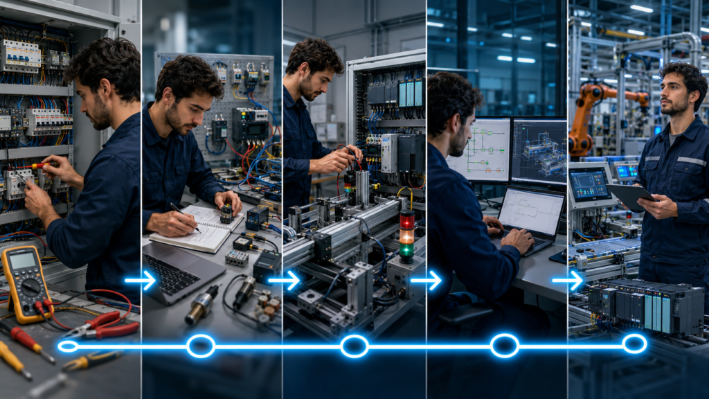
Electricians already possess many of the skills that new PLC programmers struggle to learn.
You understand what happens outside the controller:
- How a contactor actually operates
- Why an overload relay trips
- What a normally closed contact does
- How a three-wire start-stop circuit works
- Why a sensor can show 24 V but still fail under load
- How motors, valves and safety devices are wired
- What can happen when the wrong output turns on
That knowledge gives you a major advantage.
The transition is not:
Electrician
→ Forget electrical work
→ Become a software developer
It is:
Electrical circuit
→ PLC input
→ Program logic
→ PLC output
→ Real machine behaviour
You already understand the first and last parts. The main task is learning what happens inside the PLC—and how to change it without creating a more serious problem than the one you were asked to fix.
From my own route through industrial maintenance, electrical troubleshooting and control-panel work, I would not describe PLC programming as a completely separate profession. It is an additional layer built on top of electrical and machine knowledge.
That makes an experienced electrician one of the strongest candidates for the transition.
The Roadmap at a Glance
| Stage | Main objective | Evidence that you are ready to progress |
|---|---|---|
| 1 | Define the job you actually want | Clear target role and industry |
| 2 | Close electrical-control gaps | Can trace complete control circuits |
| 3 | Learn PLC fundamentals | Understand scan cycle, I/O and memory |
| 4 | Choose one PLC platform | Can configure and simulate a basic controller |
| 5 | Translate relay logic into PLC logic | Can reproduce and improve hardwired circuits |
| 6 | Build complete projects | Projects include modes, alarms and fault handling |
| 7 | Learn online troubleshooting | Can monitor safely without random edits |
| 8 | Add HMI, VFD and networking skills | Can integrate several automation components |
| 9 | Gain real-machine experience | Have completed controlled workplace tasks |
| 10 | Build a portfolio and apply | Can demonstrate practical ability to employers |
| 11 | Progress from junior programmer | Can design, commission and support complete systems |
A realistic transition is normally measured in months, not weekends.
You can understand basic ladder logic quickly. Becoming someone trusted to modify a production machine takes longer.
Step 1: Decide Which PLC Job You Actually Want
“PLC programmer” can describe several very different careers.
Maintenance PLC technician
This person primarily troubleshoots existing equipment.
Typical work includes:
- Monitoring ladder logic
- Checking PLC inputs and outputs
- Uploading and backing up programs
- Replacing failed modules
- Configuring replacement drives
- Diagnosing communication faults
- Making small approved software changes
- Supporting production breakdowns
This is often the easiest transition for an industrial electrician because it builds directly on maintenance and electrical troubleshooting.
Machine-builder PLC programmer
This person develops control software for new machinery.
Typical work includes:
- Creating the PLC project
- Writing machine sequences
- Developing the HMI
- Configuring drives and remote I/O
- Testing the machine
- Commissioning at the customer’s site
- Modifying software during production trials
This role normally requires stronger software structure and may involve significant travel.
Controls engineer
A controls engineer may handle the entire control system:
- Hardware selection
- Electrical design review
- I/O architecture
- PLC and HMI programming
- Industrial networks
- Safety integration
- Testing
- Commissioning
- Documentation
- Customer requirements
Some employers require a degree for this title. Others promote experienced electricians and technicians into it.
Process-control programmer
This route is common in:
- Food production
- Water treatment
- Chemical processing
- Pharmaceutical plants
- Energy systems
It places more emphasis on:
- Analog instrumentation
- PID control
- Valves and pumps
- SCADA
- Alarm management
- Recipes and batch control
- Redundancy
Start with the nearest transition
For most electricians, the practical order is:
Industrial electrician
→ Maintenance or automation technician
→ Junior PLC programmer
→ Controls or automation engineer
You do not have to follow every title.
The point is to gain progressively more responsibility rather than trying to jump from cable installation directly into designing a complete automated production line.
Step 2: Make Sure Your Electrical Foundation Is Industrial
An electrician may be very experienced without having worked extensively with industrial control systems.
Domestic, commercial and industrial electrical work overlap, but they are not identical.
Before focusing heavily on PLC software, make sure you can confidently work with the following.
Control circuits
You should understand:
- Two-wire and three-wire motor control
- Start-stop circuits
- Seal-in or holding contacts
- Forward-reverse control
- Electrical interlocking
- Overload contacts
- Control transformers
- 24 V DC control systems
- Relay logic
- Contactor feedback
- Automatic and manual modes
Take a conventional hardwired circuit and explain exactly what happens when each contact changes state.
Sensors
Learn the practical behaviour of:
- Inductive proximity sensors
- Capacitive sensors
- Photoelectric sensors
- Mechanical limit switches
- Pressure switches
- Float switches
- Encoders
- Analog transmitters
Understand:
- PNP versus NPN
- Sourcing versus sinking
- Normally open versus normally closed
- Two-, three- and four-wire devices
- Voltage drop under load
- Shielding
- Sensor alignment
- Switching frequency
PLC programming becomes much easier when an input is not merely I0.0, but a physical sensor whose failure modes you understand.
Motors and drives
You should be able to work with:
- Direct-on-line starters
- Star-delta starters
- Reversing starters
- Motor overload protection
- Brakes
- Variable-frequency drives
- Motor thermistors
- Safe Torque Off interfaces
A PLC programmer who cannot distinguish between a missing PLC command and a failed motor circuit is severely limited.
Electrical drawings
Practise reading:
- Power diagrams
- Control schematics
- Terminal plans
- I/O drawings
- Panel layouts
- Cable schedules
- Network diagrams
Eventually, you should be able to trace this complete path:
Field sensor
→ Terminal block
→ PLC input channel
→ PLC tag
→ Program logic
→ PLC output
→ Interposing relay
→ Solenoid valve
Step 3: Learn PLC Fundamentals Before Learning Software Menus
Do not begin by memorising where every TIA Portal or Studio 5000 menu is located.
The software will change.
The PLC concepts remain.
The PLC scan cycle
A simplified PLC cycle is:
1. Read physical inputs
2. Execute the program
3. Update physical outputs
4. Perform communication and diagnostics
5. Repeat
This explains many behaviours that confuse beginners:
- Why changing an input does not interrupt a network halfway through execution
- Why program order can matter
- Why an output can be assigned more than once
- Why one-shot instructions are needed
- Why data from the previous scan affects the next one
- Why online monitoring may appear slightly delayed
Inputs and outputs
Learn the difference between:
- Physical input
- Input process image
- Internal memory bit
- Physical output
- Output command
- Output feedback
For example:
PLC output ONdoes not prove:
Motor runningThe output may be active while:
- The interposing relay has failed
- The contactor coil is open
- The overload is tripped
- A fuse is blown
- The VFD is faulted
- The motor cable is damaged
That distinction is where your electrical background becomes valuable.
Data types
Learn at least:
BOOLBYTEWORDDWORDINTDINTREALTIME- Arrays
- Structures
Many electrical faults are simple.
Many PLC software faults occur because someone treated data as though every value were merely an ON or OFF contact.
Timers and counters
Understand:
- On-delay timer
- Off-delay timer
- Retentive timer
- Up counter
- Down counter
- Reset behaviour
- Time-base representation
- What happens when the enabling condition disappears
Do not only memorise the instruction symbol. Predict its behaviour across several PLC scans.
Edge detection
Learn why the program sometimes needs an action to occur:
Once when a signal turns onrather than:
During every scan while the signal remains onTypical uses include:
- Incrementing a production count
- Capturing an event
- Starting a sequence
- Writing a recipe
- Resetting a timer
- Sending a communication command
Program structure
Move beyond one enormous ladder routine.
Learn the purpose of:
- Main routine
- Functions
- Function blocks
- Programs
- Data blocks
- User-defined data types
- Reusable equipment modules
- State machines
Current IEC 61131-3:2025 defines the standardised PLC programming suite around Structured Text, Ladder Diagram and Function Block Diagram. Learning the underlying concepts makes it easier to move between vendor implementations.
Step 4: Choose One PLC Platform
Do not try to learn Siemens, Rockwell, Mitsubishi, Omron, Schneider and Beckhoff simultaneously.
Choose one platform that matches the equipment around you.
Choose Siemens when:
- You work in Europe
- Your factory uses S7-1200 or S7-1500 controllers
- You regularly encounter PROFINET
- Local employers frequently request TIA Portal experience
Siemens provides a large collection of free SCE learning material covering PLC programming, TIA Portal, HMI, drives, networking, security and related automation topics.
Choose Rockwell when:
- Your employer uses Allen-Bradley equipment
- You are targeting North American machine builders or factories
- CompactLogix and ControlLogix dominate local vacancies
Studio 5000 normally requires paid licensing, but Rockwell’s Connected Components Workbench Standard Edition remains available free and includes programming, simulation, device configuration and visualisation for its micro-control platform.
CCW is not identical to Studio 5000, but it can teach useful Rockwell-style automation fundamentals.
Choose CODESYS when:
- You need an accessible home-learning environment
- You want to practise IEC 61131-3 languages
- You do not yet know which hardware brand you will use
- You are interested in WAGO, Festo, Schneider, Eaton or other CODESYS-based platforms
The CODESYS Development System can be downloaded free, and the installation includes access to a demonstration SoftPLC environment.
Choose the platform used at work
The best training platform is usually the one you can see on a real machine.
You will learn faster when you can connect theory to:
- Actual I/O
- Existing drawings
- Real faults
- Real motors and sensors
- Experienced colleagues
- Production sequences
A technically superior platform that exists only on your home computer may be less useful than the older platform installed on 40 machines at your factory.
Step 5: Translate Relay Logic Into PLC Logic
Your existing electrical knowledge becomes especially useful here.
Start with circuits you already understand.
Start-stop circuit
A hardwired motor starter might use:
- Normally closed Stop button
- Normally open Start button
- Contactor holding contact
- Overload contact
- Contactor coil
Recreate the same behaviour in ladder logic.
Then improve it by adding:
- Ready condition
- Fault condition
- Running feedback
- Start timeout
- Reset requirement
- Manual and automatic modes
- Alarm indication
Forward-reverse starter
Translate:
- Forward contactor
- Reverse contactor
- Electrical interlocks
- Mechanical interlock
- Stop command
- Overload protection
into PLC logic.
Then ask what happens when:
- Both feedback contacts activate
- Neither contactor pulls in
- Direction is changed while the motor is moving
- One contactor welds closed
- The operator presses both buttons
PLC programming is not merely copying the existing relay circuit.
It is explicitly defining all the states the hardwired circuit handled naturally.
Pump control
Create a pump application with:
- Start and stop levels
- Dry-run protection
- Motor overload
- Manual mode
- Automatic mode
- High-level alarm
- Start timeout
- Runtime counter
Then build a two-pump version with:
- Duty and standby pumps
- Automatic alternation
- Failed-pump takeover
- Equalised runtime
- Maintenance lockout
This begins to resemble real industrial programming.
Step 6: Learn Both Ladder and Structured Text
Electricians usually find Ladder Diagram intuitive.
It visually resembles relay logic:
Contacts
→ Conditions
→ Coil
Start there.
Do not stop there.
Use Ladder for:
- Basic machine permissives
- Motor control
- Interlocks
- Maintenance diagnostics
- Boolean logic
- Circuits that electricians must troubleshoot online
Use Structured Text for:
- Calculations
- Loops
- Arrays
- Recipes
- Data processing
- Complex comparisons
- Communication handling
- Repetitive object processing
For example, checking 50 alarm bits individually in Ladder can create a large amount of repetitive logic.
Structured Text may handle the data more cleanly.
Use Function Block Diagram where it helps
FBD is particularly useful for:
- Analog processing
- PID control
- Signal conditioning
- Process applications
- Function-block-based libraries
The goal is not to declare one language better.
The goal is to use the clearest tool for the task.
Step 7: Build Complete Projects, Not Isolated Rungs
Many beginners complete tutorials such as:
Press button
→ Turn on lamp
Then they believe they are ready for a PLC job.
A real application needs much more.
Each portfolio project should contain:
- I/O list
- Operating description
- Manual mode
- Automatic mode
- Permissives
- Interlocks
- Alarms
- Timeouts
- Reset behaviour
- Power-recovery behaviour
- HMI controls
- Diagnostic information
Project 1: Motor control module
Include:
- Start and stop commands
- Ready input
- Running feedback
- Fault input
- Start timeout
- Stop timeout
- Manual and automatic control
- Runtime counter
- Maintenance warning
- Alarm reset
- Status code
Project 2: Conveyor with jam detection
Include:
- Infeed and discharge sensors
- Motor control
- Product tracking
- Jam timer
- Downstream permissive
- Manual jog
- Automatic mode
- Alarm recovery
- Safe restart logic
Project 3: Tank filling system
Include:
- Low and high-level sensors
- Analog level transmitter
- Fill valve
- Drain valve
- Pump
- High-high alarm
- Sensor disagreement alarm
- Manual and automatic modes
- Scaled HMI level display
Project 4: Two-pump controller
Include:
- Alternating duty
- Standby takeover
- Failed-start detection
- Runtime balancing
- Low-pressure alarm
- Manual isolation
- Maintenance counters
Project 5: VFD-controlled motor
Include:
- Start and stop
- Ready, running and fault status
- Speed reference
- Actual speed
- Local and remote modes
- Fault reset
- Communication failure
- Minimum and maximum frequency
- Start timeout
Project 6: Multi-step machine sequence
Create a state machine:
Idle
→ Check conditions
→ Load product
→ Clamp
→ Process
→ Unclamp
→ Unload
→ Complete
For every step, define:
- Entry condition
- Output commands
- Completion condition
- Timeout
- Fault response
- Manual recovery
- Restart behaviour
This is where basic PLC training begins to become engineering.
Step 8: Learn HMI Development
A PLC programmer who cannot create useful diagnostics leaves maintenance technicians guessing.
Your HMI should answer:
Why is the machine stopped?Not merely:
Machine not readyBuild screens for:
- Machine overview
- Manual controls
- Active alarms
- Alarm history
- Setpoints
- Maintenance
- I/O diagnostics
- Sequence status
- Drive status
Show missing permissives
Instead of one general message:
Motor unavailableshow:
Motor unavailable:

- Safety circuit not healthy
- VFD not ready
- Downstream conveyor stopped
- Local isolator open
Your electrician and maintenance background helps here.
You already know what information would have saved time during a breakdown.
Step 9: Learn VFD Integration
You do not need to become a drive specialist immediately.
You should understand how a PLC exchanges the following with a VFD:
PLC to drive:
- Run command
- Direction
- Speed reference
- Fault reset

Drive to PLC:
- Ready
- Running
- At speed
- Faulted
- Actual speed
- Current
- Fault code
Practise both:
- Hardwired control
- Fieldbus control
Understand what happens when communication fails.
A good program should not simply continue displaying “Running” because the last received drive status happened to be true.
Step 10: Learn Industrial Networking
Modern PLC programming is inseparable from networking.
Learn the fundamentals of:
- IP addresses
- Subnet masks
- Default gateways
- MAC addresses
- Switches
- Device names
- Duplicate addresses
- TCP and UDP
- Network topology
Then study the protocol used around you:
- PROFINET
- EtherNet/IP
- EtherCAT
- Modbus TCP
- Modbus RTU
- PROFIBUS
- OPC UA
You should be able to distinguish between:
PLC program problemand:
Remote I/O is offline because its device name or IP configuration is wrongDo not begin with advanced managed-switch configuration.
Begin by connecting a laptop and PLC reliably, checking addresses and identifying the communication path.
Step 11: Learn Safe Online Work
Going online with a production PLC is not the same as experimenting in a simulator.
Before connecting, confirm:
- Correct machine
- Correct controller
- Correct project
- Correct software version
- Correct communication route
- Current PLC mode
- Machine condition
- Authorisation to work online
Understand upload and download
Upload
PLC → Computer
Download
Computer → PLCConfusing them can overwrite the only working machine program.
Before making a change
- Upload or back up the running project.
- Save a dated copy.
- Compare it with the offline project.
- Record the requested modification.
- Understand every affected output.
- Check whether safety logic is involved.
- Plan how to test the change.
- Plan how to restore the previous version.
During the change
- Use the smallest practical modification.
- Avoid changing unrelated logic.
- Monitor affected conditions.
- Keep personnel outside hazardous areas.
- Test abnormal conditions as well as normal operation.
- Do not leave forces enabled.
After the change
- Save the final project.
- Record what changed.
- Update comments and drawings.
- Remove temporary logic.
- Verify that no forces remain.
- Retain the previous working version.
An online edit is not safe merely because the software allows it.
Step 12: Get Access to Real Hardware
Simulation is valuable, but it cannot reproduce every physical problem.
A basic training setup could contain:
- Small PLC
- 24 V DC power supply
- Pushbuttons
- Selector switches
- Indicator lamps
- Proximity sensor
- Relay
- Small contactor
- Terminal blocks
- Ethernet switch
- Optional small HMI or VFD
Keep mains-powered motor circuits separate until you have a suitable, safely designed training arrangement.
You can learn a great deal using only 24 V DC.
What real hardware teaches
A simulator does not teach you:
- Incorrect PNP/NPN wiring
- Loose terminals
- Sensor voltage drop
- Output leakage current
- Relay contact bounce
- Communication cable problems
- Incorrect device addressing
- Physical input delay
- Faulty terminal connections
You do not necessarily need to buy everything yourself.
Possible access routes include:
- Equipment at your current employer
- Technical college laboratories
- Used training hardware
- Vendor courses
- Maker spaces
- Panel-building workshops
- A supervised test bench at work
Step 13: Use Your Current Electrical Job as the Bridge
The best opportunity may already be inside your workplace.
Do not begin by asking to rewrite the main production-line program.
Begin with low-risk, useful tasks.
Volunteer to:
- Create PLC and HMI backups
- Label controllers and network addresses
- Update I/O lists
- Investigate recurring sensor faults
- Record drive parameters
- Assist with replacement PLC hardware
- Perform supervised I/O checks
- Improve electrical drawings
- Help during commissioning
- Add reviewed diagnostic messages
- Compare offline and online projects
Work with the existing controls engineer
Ask to observe:
- How projects are structured
- How changes are requested
- How backups are managed
- How commissioning is performed
- How software is tested
- How network faults are diagnosed
Do not present yourself as someone trying to take over their position.
Present yourself as an electrician who can make the controls team’s work easier.
Build trust gradually
The progression might look like:
Monitor logic
→ Identify missing condition
→ Back up project
→ Change one timer under supervision
→ Add one alarm
→ Modify one equipment block
→ Program one small machine section
Production access is earned through reliable decisions.
Step 14: Learn How to Troubleshoot Logic Properly
Do not scroll randomly through the program looking for a red or green contact.
Start from the symptom.
Suppose a motor will not start.
Trace backwards:
Motor not running
← Contactor not energised
← PLC output off
← Motor command false
← Start permissive missing
← Safety-ready input false
← Safety relay not reset
Or forward from the field:
Sensor physically active
→ Voltage present at terminal
→ PLC input LED active
→ Input tag true
→ Sequence condition true
→ Output command generated
Separate command from feedback
For every device, distinguish:
- Commanded state
- Electrical output state
- Physical feedback state
- Process result
Example:
Pump command = ON
PLC output = ON
Contactor feedback = ON
Flow switch = OFF
That suggests a different problem from:
Pump command = OFFThe first may be mechanical, hydraulic or instrumentation-related.
The second is still inside the control decision.
Step 15: Build a Portfolio That Looks Like Industrial Work
Do not fill your portfolio with screenshots of one timer instruction.
For each project, include:
Project summary
Explain:
- What the machine does
- What hardware was assumed
- Which PLC platform was used
- Which problems the program handles
I/O list
Example:
| Address | Tag | Description |
|---|---|---|
I0.0 | Start_PB | Operator Start pushbutton |
I0.1 | Stop_OK | Stop circuit healthy |
I0.2 | Motor_FB | Motor contactor feedback |
Q0.0 | Motor_CMD | Motor contactor command |
Sequence description
Write the sequence in plain language before showing the program.
Software structure
Explain:
- Device blocks
- Sequence logic
- Alarm handling
- HMI communication
- Data structures
Failure behaviour
Show what happens when:
- Feedback is missing
- A sensor remains active
- Communication fails
- Power is restored
- The operator presses Reset
- The machine stops halfway through a cycle
Demonstration
A short video can show:
- Normal cycle
- Fault injection
- Alarm display
- Recovery
- Manual mode
Do not use confidential employer code, drawings or machine information.
Create simplified original examples.
Step 16: Rewrite Your CV Around Transferable Skills
Do not describe yourself only as:
Electrician with ten years of experienceTranslate your work into automation-relevant evidence.
Weak description
Repaired electrical equipment and carried out maintenance.
Stronger description
Diagnosed industrial machine faults involving 24 V DC controls, three-phase motors, contactors, overload relays, proximity sensors, VFDs and PLC input/output circuits.
Weak description
Worked with PLCs.
Stronger description
Used online PLC monitoring to trace interlocks and permissives, verified field signals against electrical drawings and assisted with controlled program backups and modifications.
Include:
- PLC platforms
- HMI software
- VFD brands
- Industrial protocols
- Electrical qualifications
- Commissioning work
- Machinery types
- Project portfolio
- Relevant training
Do not call yourself an advanced PLC programmer because you completed one online course.
Employers usually discover the truth during technical interviews.
Step 17: Apply for Bridge Roles
Searching only for “PLC Programmer” may hide suitable entry positions.
Look for:
- Automation technician
- Controls technician
- PLC technician
- Industrial maintenance technician
- Electrical automation technician
- Junior automation engineer
- Field-service technician
- Commissioning technician
- Panel technician
- Mechatronics technician
- Junior controls engineer
A bridge role is valuable when it gives you:
- Regular PLC access
- Experienced colleagues
- Commissioning exposure
- Permission to make controlled changes
- Multiple machine types
- Training
- Gradually increasing responsibility
A maintenance position that never allows you to connect to a PLC may not move you forward.
A technician position with a modest title but daily programming exposure may be a much better opportunity.
Step 18: Understand the Qualification Issue
PLC programming itself is not always a regulated occupation.
Electrical installation and sign-off responsibilities may be.
Across the EU, regulated professions and qualification-recognition requirements differ by country. Someone moving between countries may need formal recognition before performing particular regulated electrical work, especially where health and safety are involved.
This creates an important distinction:
Permission to program a controlleris not necessarily the same as:
Legal authority to design, certify or modify every electrical installationYour electrician qualification remains valuable even after you move into controls.
A degree may improve access to formal controls-engineering roles, but it is not the only possible route.
A Realistic 12-Month Transition Plan
The timeline below is an estimate for someone who already has meaningful industrial electrical experience and can study approximately five to ten hours per week.
Months 1–2: PLC fundamentals
Study:
- Scan cycle
- Inputs and outputs
- Ladder logic
- Timers
- Counters
- Edge detection
- Data types
- Basic troubleshooting
Build:
- Start-stop circuit
- Forward-reverse circuit
- Traffic-light sequence
- Simple pump control
Months 3–4: One platform in depth
Learn:
- Hardware configuration
- Project creation
- Addressing
- Program blocks
- Online monitoring
- Simulation
- Upload and download
- Diagnostics
Build:
- Reusable motor block
- Conveyor control
- Alarm system
Months 5–6: Structured projects
Learn:
- Function blocks
- Data structures
- Structured Text
- State machines
- Manual and automatic modes
- Restart behaviour
Build:
- Multi-step machine
- Two-pump alternation system
- Tank-filling sequence
Months 7–8: HMI and VFDs
Learn:
- HMI tags
- Alarm display
- Faceplates
- Setpoints
- Drive command and status
- Analog speed reference
- Fieldbus basics
Build:
- VFD motor project
- HMI diagnostic screens
- Drive-fault handling
Months 9–10: Networking and troubleshooting
Learn:
- IP configuration
- PROFINET or EtherNet/IP
- Remote I/O
- Communication-loss handling
- PLC diagnostics
- Program comparison
- Safe online workflow
Practise:
- Incorrect device address
- Missing remote-I/O module
- Broken communication
- Mismatched project
Months 11–12: Portfolio and workplace transition
Complete:
- Three polished projects
- Demonstration videos
- Project descriptions
- Updated CV
- Applications for bridge roles
Seek:
- Supervised work on real machines
- Commissioning assistance
- PLC backup responsibility
- Small approved modifications
After 12 months, you may be ready for a junior or technician-level PLC role.
You will not yet know everything.
Neither does anyone else.
Skills to Learn After Getting the First PLC Job
Getting hired is the beginning of the transition.
Continue developing:
Program architecture
Learn:
- Modular equipment blocks
- State machines
- Standard interfaces
- Reusable libraries
- Naming standards
- Version management
Functional safety
Understand:
- Safety relays
- Safety PLCs
- Emergency stops
- Guard switches
- Safe Torque Off
- Restart prevention
- Validation boundaries
Do not modify safety code simply because it resembles ordinary ladder logic.
Analog and process control
Learn:
- 4–20 mA
- 0–10 V
- Scaling
- Filtering
- Sensor fault detection
- PID fundamentals
- Control valves
Motion control
Progress into:
- Servos
- Homing
- Positioning
- Electronic gearing
- Cam profiles
- Motion faults
Software tools
Useful additional skills include:
- Git or another version-control approach
- SQL
- OPC UA
- MQTT
- Basic Python
- Virtual commissioning
- Automated testing
You do not need all of these for your first job.
They expand the kind of automation work you can perform later.
Common Transition Mistakes
Learning only the programming software
Knowing where the timer button is located is not the same as knowing when a timer should be used.
Learn control behaviour, not merely menus.
Buying expensive hardware too early
Start with simulation or an affordable controller.
Do not spend several thousand euros before you know which platform local employers use.
Learning six platforms superficially
One platform in depth is more valuable than six platforms at tutorial level.
Ignoring Structured Text
Ladder is an excellent starting point for electricians.
Modern projects increasingly require data handling that is much easier in Structured Text.
Building only normal-operation logic
Anyone can make a simulated conveyor move.
Employers care about what happens when it does not move.
Treating every machine fault as a software fault
Your electrical background should prevent this mistake.
Use it.
Making unapproved workplace changes
Do not use production machinery as a personal training system.
Build trust and work under an approved change process.
Downloading an old project
Always determine whether the offline project matches the running controller.
Leaving forces active
Forcing is useful for controlled testing and dangerous when forgotten.
Hiding behind the electrician title
At some point, you must begin writing programs rather than only saying you plan to learn.
Build complete projects and accept small supervised responsibilities.
How Long Does It Take?
For an industrial electrician:
Basic PLC understanding:
1–3 months

Useful simulation projects:
3–6 months

Ready for junior technician-level PLC duties:
6–12 months

Comfortable on real machines:
1–2 years

Strong independent programmer or commissioning engineer:
Several years of varied project experience
These are practical estimates, not fixed rules.
The transition can be faster when:
- Your current employer uses PLCs
- You have a skilled mentor
- You work on machinery daily
- You study consistently
- You are allowed to assist with real projects
It may take longer when:
- Your work is entirely domestic or construction-based
- You have no industrial hardware access
- You practise only by watching videos
- You switch platforms constantly
- You avoid troubleshooting and commissioning
Final Verdict
An electrician does not begin the PLC transition from zero.
You already understand the physical system the PLC is controlling.
Your strongest route is:
Industrial electrical fundamentals
→ PLC scan and programming concepts
→ One platform in depth
→ Complete simulated projects
→ Safe online troubleshooting
→ HMI, drives and networks
→ Supervised real-machine work
→ Junior PLC or automation role
→ Controls engineering responsibility
Do not abandon your electrical identity.
Build on it.
The programmer who knows software but cannot trace a control circuit has a serious weakness.
The electrician who understands the circuit, the machine and the PLC logic can become the person who finds faults others cannot.
That is the real transition:
Not from electrician to “computer person.”
From someone who understands the wiring to someone who understands the entire control system.