Encoders are used when a machine needs to know more than just “something moved.”
A limit switch can tell you that a mechanism reached the end. A proximity sensor can tell you that a metal part is nearby. But an encoder can tell you how far something moved, how fast it moved, and often which direction it moved.
That is why encoders are so important in motion control.
You find them in CNC machines, robots, conveyors, cutting machines, measuring wheels, servo systems, drilling machines, assembly equipment, packaging lines, and many other industrial applications where position feedback matters.
Without feedback, motion control is basically guessing. And machines are not very good at guessing politely.
What Is an Encoder?
An encoder is a motion feedback sensor that converts mechanical movement into electrical signals.
These signals are usually pulses or digital codes that a controller can read. The controller then uses this information to calculate position, speed, distance, or direction.
Encoders can detect two main types of motion:
- Rotary motion
- Linear motion
A rotary encoder measures shaft rotation. A linear encoder measures straight-line movement.
Both types are used to provide feedback to PLCs, motion controllers, servo drives, counters, or other control systems.
In simple words:
Machine moves.
Encoder produces signals.
Controller counts or reads the signals.
Position and speed become known.
That is the basic idea.
Why Encoders Are Used
Many industrial processes need precise movement.
For example, a cutting machine may need to feed exactly 250 mm of material before cutting. A robot joint must rotate to a specific angle. A CNC machine must know the position of an axis. A conveyor system may need to track product movement. A motor drive may need speed feedback to maintain constant velocity.
Encoders make this possible by giving the control system feedback from the real mechanical movement.
Common encoder feedback includes:
- Shaft position
- Linear position
- Travel distance
- Rotation speed
- Linear speed
- Direction of movement
- Reference or home position
This feedback allows the control system to correct, stop, count, position, synchronize, or monitor the machine movement.
A motor can turn. An encoder tells you what actually happened.
And yes, those two are not always the same thing.
Rotary Encoders
A rotary encoder measures rotational movement.
It is usually connected to a rotating shaft, motor shaft, gearbox shaft, measuring wheel, or mechanical axis. As the shaft turns, the encoder generates signals related to the rotation.
Rotary encoders are available in different mechanical styles, including:
- Solid shaft encoders
- Hollow shaft encoders
- Through-shaft encoders
- Motor-mounted encoders
- Coupled shaft encoders
A solid shaft encoder is connected to the machine shaft using a coupling. A hollow shaft encoder fits directly over the shaft.
Rotary encoders are commonly used for:
- Motor speed feedback
- Shaft position measurement
- Servo control
- Robot joint feedback
- Conveyor tracking
- Gearbox monitoring
- Indexing tables
- Measuring wheels
If the machine part rotates and you need feedback from it, a rotary encoder is usually one of the first sensor types to consider.
Linear Encoders
A linear encoder measures straight-line movement.
Instead of following rotation, it follows motion along a linear path. This is useful for machine axes, slides, tables, cylinders, measuring systems, and precision positioning equipment.
Linear encoders are commonly used in:
- CNC axes
- Milling machines
- Grinding machines
- Presses
- Linear stages
- Positioning tables
- Cutting machines
- Measuring equipment
A linear encoder may use a scale and reading head. As the reading head moves along the scale, the encoder generates position information.
In some applications, a rotary encoder with a measuring wheel can also be used to measure linear distance. The wheel turns as material moves, and the encoder pulses are converted into length.
That is common in cutting, printing, labeling, and conveyor applications.
Absolute and Incremental Encoders
Encoders are usually divided into two main output types:
- Absolute encoders
- Incremental encoders
Both measure motion, but they provide information in different ways.
This difference is very important when choosing an encoder.
What Is an Absolute Encoder?
An absolute encoder provides a unique digital value for each position.
This means the controller can know the actual position directly, even after power has been turned off and back on. The encoder does not need to count from zero every time the machine starts.
It already knows where it is.
That is the big advantage.
An absolute encoder has a reference position built into its measuring system. Each shaft angle or linear position corresponds to a specific code. When the controller reads that code, it knows the position.
For example, if a rotary absolute encoder is at 180 degrees, it outputs a digital code representing that position. If power is lost and restored, the encoder still reports the correct position after restart.
No homing required in many cases.
That can save time and avoid unnecessary machine movement.
Advantages of Absolute Encoders
Absolute encoders are useful when the machine must know its position immediately after startup.
Main advantages include:
- Direct position reading
- No need to count pulses from zero
- Position retained after power loss
- Reduced need for homing
- Good for safety-critical or complex axes
- Useful for multi-axis machines
- Helpful where movement after restart is not allowed
Common applications include:
- Robotics
- Servo systems
- CNC machines
- Positioning tables
- Wind turbines
- Cranes
- Medical equipment
- Automated storage systems
If losing position after power failure would cause problems, an absolute encoder is often the better choice.
What Is an Incremental Encoder?
An incremental encoder produces pulses as movement occurs.
It does not directly tell the controller the absolute position. Instead, the controller must count the pulses to calculate how far the shaft or linear axis has moved.
For rotary encoders, the output is usually given as pulses per revolution, often written as PPR.
For linear encoders, the output may be pulses per millimeter or another distance unit.
For example, if a rotary encoder produces 1,000 pulses per revolution, then one full shaft rotation gives 1,000 pulses. The controller counts these pulses and calculates position, speed, or distance.
The important point is this: an incremental encoder only knows movement relative to a starting point.
If power is lost, the controller may lose the counted position unless the system stores it or performs a homing procedure.
Incremental Encoder Homing
Because incremental encoders do not provide absolute position by themselves, many systems need homing after startup.
Homing means the machine moves to a known reference point. This reference point may be detected by a limit switch, proximity sensor, mechanical stop, or encoder index pulse.
Once the home position is found, the controller sets its position counter to zero or to a known value. After that, it counts encoder pulses to track movement.
This is very common in CNC machines, packaging machines, cutting systems, and many PLC-controlled motion applications.
A machine with incremental feedback often wakes up and says, “Where am I?”
Homing is the answer.
Encoder Resolution
Encoder resolution tells how many measurement steps the encoder provides.
For rotary incremental encoders, resolution is often specified as:
- Pulses per revolution
- Counts per revolution
- Lines per revolution
For linear encoders, resolution may be specified as:
- Pulses per millimeter
- Micrometers per count
- Counts per unit distance
Higher resolution means the controller receives more measurement information for the same movement.
For example, a 100 PPR encoder gives 100 pulses per revolution. A 1,000 PPR encoder gives 1,000 pulses per revolution. A 10,000 PPR encoder gives even finer position information.
But higher resolution is not always automatically better.
The PLC or controller must be able to count the pulses fast enough. The wiring must be good. Electrical noise must be controlled. The mechanical coupling must be stable.
Otherwise, high resolution just gives you more opportunities to count badly.
Simple Binary Position Encoding
Absolute encoders often use a digital code to represent position.
A very simple example is a 3-bit encoder. Three bits can create eight different position sectors around one full rotation.
Each sector has its own binary combination.
For example:
| Sector | Bit 1 | Bit 2 | Bit 3 | Approximate Angle Range |
|---|---|---|---|---|
| 0 | OFF | OFF | OFF | 0°–45° |
| 1 | OFF | OFF | ON | 45°–90° |
| 2 | OFF | ON | OFF | 90°–135° |
| 3 | OFF | ON | ON | 135°–180° |
| 4 | ON | OFF | OFF | 180°–225° |
| 5 | ON | OFF | ON | 225°–270° |
| 6 | ON | ON | OFF | 270°–315° |
| 7 | ON | ON | ON | 315°–360° |
With only three bits, the encoder can divide one rotation into eight parts. That is not very precise, but it explains the idea.
If more position accuracy is needed, the encoder needs more bits.
More bits mean more unique position values.
For example:
- 8-bit encoder = 256 positions per revolution
- 10-bit encoder = 1,024 positions per revolution
- 12-bit encoder = 4,096 positions per revolution
- 16-bit encoder = 65,536 positions per revolution
So yes, bits matter.
Incremental Encoder Channels
Incremental encoders may have one or more output channels.
The most common channels are:
- Channel A
- Channel B
- Channel Z
Each channel has a specific purpose.
Single-Channel Encoder
A single-channel encoder produces one pulse train.
This can be used to measure speed or count movement, but it cannot determine direction by itself.
If the shaft turns forward, pulses are produced.
If the shaft turns backward, pulses are also produced.
The controller sees pulses either way unless direction is provided from another source.
Single-channel encoders are useful for simple speed measurement or counting where direction does not matter.
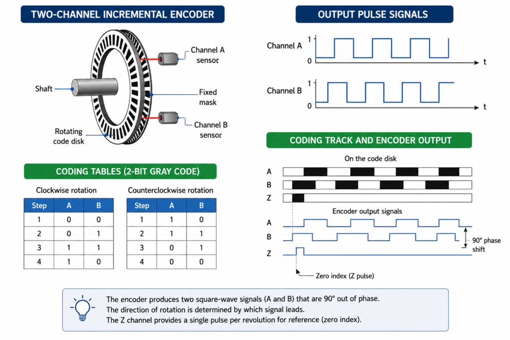
Two-Channel Quadrature Encoder
A two-channel incremental encoder produces two pulse trains: channel A and channel B.
These signals are shifted by 90 electrical degrees. This is called quadrature output.
The controller compares which channel leads the other.
If A leads B, the shaft is turning one direction.
If B leads A, the shaft is turning the opposite direction.
This allows the control system to detect direction as well as movement.
Quadrature encoders are very common in motion control because they provide reliable direction information.
Z Channel or Index Pulse
Many incremental encoders include a third channel called:
- Z channel
- Index channel
- Zero pulse
- Reference pulse
This channel usually produces one pulse per revolution on a rotary encoder.
The Z pulse is used as a reference mark. During homing, the controller can use this pulse to establish a precise reference position.
For linear encoders, an index pulse may appear at a specific known point along the travel.
The Z channel is especially useful when the system needs better repeatability during homing.
A limit switch can get you near home.
The Z pulse can help define it more precisely.
Single, Double, and Quadruple Counting
Incremental encoder resolution depends not only on the encoder itself, but also on how the controller counts the pulses.
With quadrature encoders, the controller may count:
- Single resolution
- Double resolution
- Quadruple resolution
In single resolution, the controller counts only the rising edge of one channel.
In double resolution, it counts both rising and falling edges of one channel.
In quadruple resolution, it counts rising and falling edges of both A and B channels.
Quadruple counting gives four times more counts than basic single-edge counting.
For example, if an encoder has 1,000 pulses per revolution:
- Single counting may give 1,000 counts per revolution
- Double counting may give 2,000 counts per revolution
- Quadruple counting may give 4,000 counts per revolution
This gives better position resolution without changing the encoder.
Nice trick, actually.
But the controller must support it, and the signal quality must be good enough.
Direction Detection With A and B Channels
Direction is determined by the phase relationship between channel A and channel B.
If channel A changes before channel B, the controller counts in one direction. If channel B changes before channel A, it counts in the opposite direction.
This is why wiring matters.
If A and B are swapped, the counted direction may be reversed.
This is a very common commissioning issue. The machine moves forward, but the position value counts down. Or the axis moves toward home and the controller thinks it is moving away.
Not a disaster. Just swap A and B logically or physically, depending on the system.
But do it intentionally, not randomly.
Encoder Technologies
Encoders can use different sensing technologies inside.
Common encoder technologies include:
- Optical
- Magnetic
- Laser
- Capacitive
- Inductive, in some designs
The most common are optical and magnetic.
Optical Encoders
Optical encoders use light passing through or reflecting from a coded disk or scale.
A light source and photodetectors read patterns on the disk or scale. As movement occurs, the detected light pattern changes and produces output signals.
Optical encoders can provide high accuracy and high resolution.
However, they may be sensitive to contamination if not properly sealed. Dust, oil, vibration, and mechanical damage can affect performance in harsh environments.
Magnetic Encoders
Magnetic encoders use magnetic fields to detect position.
They are often more tolerant of dirt, dust, oil, and moisture than optical encoders. This makes them useful in tough industrial environments.
Magnetic encoders may not always reach the same resolution as high-end optical encoders, but they can be very robust.
In real factories, robustness sometimes beats theoretical precision.
Especially when coolant is flying everywhere.
Encoder Output Signals
Encoders can have many different output signal types depending on the application and controller.
Common incremental output types include:
- Push-pull
- NPN
- PNP
- Open collector
- Line driver
- TTL
- HTL
- Differential A+/A-, B+/B-, Z+/Z-
Common absolute encoder interfaces include:
- Parallel binary
- Gray code
- SSI
- CANopen
- Profibus
- Profinet
- EtherCAT
- EtherNet/IP
- IO-Link, in some simpler devices
The output type must match the PLC, drive, counter card, or motion controller input.
This is not optional.
A 5 V TTL encoder connected to the wrong 24 V input can turn into an expensive lesson.
Why Encoders Need Special Inputs
Encoders are usually not wired like ordinary limit switches.
A standard PLC digital input may be too slow to count encoder pulses, especially at high speed. Incremental encoders often need a high-speed counter input, encoder module, motion card, or drive feedback input.
This is because encoder pulses can come very quickly.
If the controller cannot count them fast enough, pulses are missed. Missed pulses mean wrong position.
For simple low-speed counting, a PLC high-speed input may be enough. For precise motion control, a dedicated encoder input is usually required.
So, while a limit switch gives one slow digital signal, an encoder may generate thousands of pulses per second.
Different animal.
Encoder Applications
Encoders are used in many industrial systems where motion feedback is needed.
Common applications include:
- Robotics
- CNC machines
- Servo motor feedback
- Conveyor tracking
- Measuring wheels
- Cutting machines
- Drilling machines
- Assembly machines
- Packaging machines
- Printing machines
- Elevator positioning
- Crane positioning
- Wind turbines
- Indexing tables
- Roll length measurement
- Speed measurement
- Position control
In robotics, encoders help control joint position.
In CNC machines, they help measure axis position.
In cutting machines, an encoder measuring wheel can track material length.
In conveyors, encoders can synchronize product position with machine actions.
Without encoders, many precise machines would be blind.
Encoder in a Measuring Wheel Application
One simple and common example is a measuring wheel with an encoder.
The wheel touches a moving material, such as film, paper, cable, textile, or sheet product. As the material moves, the wheel rotates. The encoder connected to the wheel shaft generates pulses.
The controller converts those pulses into length.
For example, if the wheel circumference is 200 mm and the encoder produces 1,000 pulses per revolution, then each pulse represents 0.2 mm of travel before any quadrature multiplication.
This can be used for:
- Cutting to length
- Printing registration
- Label placement
- Roll measurement
- Conveyor tracking
The accuracy depends not only on the encoder, but also on wheel diameter, slip, pressure, material surface, and mounting.
Because again, the sensor may be perfect while the mechanics quietly ruin everything.
Encoder Feedback in Servo Systems
Servo systems often use encoders for closed-loop control.
The controller commands the motor to move. The encoder reports the actual position or speed. The drive compares command and feedback, then adjusts motor current to reduce the error.
This feedback loop allows precise control of:
- Position
- Speed
- Acceleration
- Torque response
- Synchronization
A servo without encoder feedback is not really doing precise servo control. It is more like hoping the motor did what you asked.
Encoders make the loop closed. And closed-loop control is where the magic happens — well, engineering magic.
Advantages of Encoders
Encoders have several major advantages.
They provide detailed motion feedback, not just a simple present/not-present signal. They can measure position, speed, distance, and direction. They are available in many resolutions and output types. They can be used in both rotary and linear motion systems.
Main advantages include:
- Precise position feedback
- Speed measurement
- Direction detection
- High resolution options
- Rotary and linear versions
- Suitable for motion control
- Useful for closed-loop systems
- Can improve machine accuracy
- Absolute versions retain position after power loss
- Incremental versions are cost-effective and widely used
Encoders are one of the key components behind accurate modern automation.
Limitations of Encoders
Encoders also have limitations.
They require correct mechanical mounting. Couplings must be aligned. Cables must be protected. Electrical noise can affect pulse signals. Controllers must support the encoder output. Incremental encoders may require homing. High-resolution encoders can produce very fast signals that not every PLC can count.
Common limitations include:
- Requires proper mechanical coupling
- Sensitive to misalignment
- Signal wiring must be correct
- Noise can cause false counts
- Standard PLC inputs may be too slow
- Incremental encoders lose position after power loss
- Absolute encoders are usually more expensive
- Optical encoders may need protection from contamination
- Measuring wheels can slip
So an encoder is not just “connect wires and done.”
It needs good mechanics, good wiring, and a controller that can read it properly.
Installation Tips
Good encoder installation is critical for reliable operation.
Practical tips include:
- Use the correct coupling
- Avoid shaft misalignment
- Do not overload encoder bearings
- Mount the encoder firmly
- Protect cables from bending and pulling
- Use shielded cable where required
- Ground shields correctly
- Keep encoder cables away from motor power cables
- Match output type to controller input
- Use differential signals for long cables or noisy areas
- Check pulse frequency against counter input limits
- Verify direction counting during commissioning
- Perform homing correctly for incremental systems
- Test at real machine speed, not only slow jog speed
Slow testing can hide problems. A signal that looks fine at low speed may fail when the machine runs at full speed.
That one is sneaky.
Final Thoughts
Encoders are motion feedback sensors used to measure rotation, linear movement, position, speed, distance, and direction.
Rotary encoders follow shaft rotation. Linear encoders follow straight-line movement. Absolute encoders provide a direct position code and can retain position after power loss. Incremental encoders generate pulses that must be counted by the controller.
Incremental encoders may have A and B channels for direction detection and a Z channel for reference or homing. By counting rising and falling edges of the pulse signals, the controller can improve measurement resolution.
Encoders can be optical, magnetic, laser-based, or use other sensing technologies. In automation, the main concern is usually not the internal technology alone, but whether the encoder has the right resolution, output type, mechanical design, and controller compatibility.
They are used in robotics, CNC machines, cutting systems, measuring wheels, assembly machines, conveyors, servo systems, and many other applications where motion must be controlled accurately.
A basic sensor tells you something happened.
An encoder tells you how much it happened, how fast it happened, and often which way it happened.
That is why encoders matter so much in industrial automation.