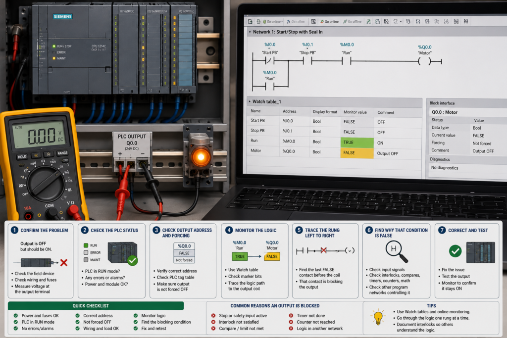
A motor refuses to start, a solenoid will not energise or a valve remains closed. The output LED is off, but the ladder program contains dozens of contacts, timers, interlocks and sequence bits.
Which condition is actually blocking the output?
The slow approach is to inspect every network and guess. The better approach is to begin at the output coil, monitor the logic online and trace the false condition backwards until you reach the original cause.
This guide uses Siemens TIA Portal terminology, but the same troubleshooting method works with most PLC platforms.
First, Confirm That the PLC Output Is Really Off
Before investigating ladder logic, compare:
- The physical output LED
- The output address, such as
%Q0.0 - The internal command bit
- The final output coil in the program
- The voltage at the PLC output terminal
These are not always the same signal.
A typical program may use several stages:
Start request → Motor command → Safety permissive → Output command → Physical output
The motor command could be true while the physical output remains false because a later interlock blocks it.
If the output address is true but no voltage appears at the terminal, the problem is probably outside the ladder condition. Check the output module, load supply, fuse, common wiring and channel diagnostics.
Step 1: Go Online and Monitor the Network
Open the block containing the output logic and enable online monitoring.
In ladder logic, highlighted power flow shows which conditions are true. Follow the rung from the left power rail toward the output coil.
The first contact or instruction without active power flow is often the condition blocking the output.
Siemens ladder networks are processed from left to right, while rungs and networks execute from top to bottom. Understanding that order is important when a tag is written more than once during the same PLC scan.
Do not stop at the name of the false contact. A contact called Motor_Permissive may itself be generated by another block containing ten more conditions.
Open its cross-reference and continue tracing.
Step 2: Use Cross-References
Right-click the output tag or select it and open its cross-reference information.
Cross-references show:
- Where the tag is read
- Where it is written
- Which blocks use it
- Which instruction accesses it
- Whether it appears in PLC, HMI or data-block logic
TIA Portal’s cross-reference tools are specifically designed to show where operands and tags are used and allow you to jump directly to each point of use.
For an output that will not energise, look first for every location marked as a write access.
One of the most common faults is the same output being controlled in several places.
Step 3: Look for Duplicate Output Coils
Suppose %Q0.0 is energised in Network 5 but written false again in Network 40.
The output may briefly become true during program execution, but the later instruction becomes the final value stored in the output process image.
A normal ladder coil writes the rung’s current logic result to the addressed bit. If the rung is false, the coil writes false.
This means that duplicate coils do not behave like parallel physical switches. The later executed write can overwrite the earlier result.
Search for:
- Normal coils using the same output
- Set and reset coils
MOVEinstructions writing an output byte or word- Block outputs mapped to the same address
- SCL assignments to the same tag
- HMI or communication data writing the command
A better program structure usually creates one final output coil and combines all permitted commands before it.
Step 4: Separate the Command From the Permissives
Large rungs become difficult to troubleshoot when every condition is placed directly before the physical output.
Break the logic into understandable groups:
- Start request
- Automatic-mode command
- Manual-mode command
- Safety healthy
- Process permissives
- Fault-free condition
- Final output command
For example:
Motor_Run_Request := Auto_Request OR Manual_Request
Motor_Permissive := Safety_OK AND Overload_OK AND Guard_Closed
Motor_Output := Motor_Run_Request AND Motor_Permissive
This structure makes the blocking condition much easier to identify in a watch table.
Do not modify a validated machine program merely to make troubleshooting easier without following the required change-control procedure. Temporary monitoring tags may be safer than restructuring production logic during a breakdown.
Step 5: Inspect Normally Closed Contacts Carefully
A normally closed ladder contact is true when its associated Boolean tag is false.
This can be confusing when the tag name is negative.
Consider a normally closed contact named:
No_Fault
If No_Fault becomes true, the normally closed instruction opens and blocks the rung—even though the tag name sounds healthy.
Clear naming reduces this problem. Prefer either:
- Normally open contact:
Motor_Fault_Free - Normally closed contact:
Motor_Fault
Avoid combining negative names with inverted contacts unless there is a clear reason.
While online, look at the actual tag value rather than guessing from the symbol.
Step 6: Check Interlocks and Permissives
Typical conditions that block an output include:
- Emergency stop not reset
- Safety relay not healthy
- Motor overload tripped
- Guard door open
- Pressure too low
- Tank level too high or too low
- Another actuator not in position
- Machine not in automatic mode
- Sequence step inactive
- Communication device not ready
- VFD not ready
- Previous fault not acknowledged
Many programs create a general permissive bit such as Conveyor_Ready.
Cross-reference that bit and open the network where it is generated. Continue until you find the original physical signal or program state that is false.
Do not bypass an interlock simply because it prevents an output from turning on. The blocked output may be correct behaviour.
Step 7: Check Timers
Timers can make a condition look permanently blocked when the real issue is that the timer never finishes.
Monitor:
- Timer input
- Elapsed time
- Preset time
- Timer output
- Reset condition
Common timer-related problems include:
- Input drops out before the preset time
- Timer is continuously reset
- Preset time is entered in the wrong units
- Off-delay logic keeps another condition active
- The wrong timer instance is reused
- A sequence leaves the timer’s calling block
TIA Portal IEC timers store their current state in an associated timer instance, so monitoring the correct instance is essential.
If the timer input flickers too quickly to observe, use a trace or temporary dropout counter.
Step 8: Check Set and Reset Logic
A set coil latches a bit true. A reset coil clears it later.
When an output remains blocked, you may find that a fault or inhibit bit was set earlier and never reset.
Cross-reference both the set and reset instructions.
Check:
- What sets the bit
- What should reset it
- Whether the reset network is being executed
- Whether reset conditions can ever become true
- Whether another set instruction immediately activates it again
- Whether the bit is retentive after a PLC restart
Do not simply reset the bit manually without understanding why it was set.
Step 9: Check the Active Sequence Step
Many machines use sequence or state logic.
The output may be allowed only during one step:
Step_30 AND Clamp_Closed AND Pressure_OK → Extend_Valve
If the sequence is stuck in Step 20, the output rung remains false even though all physical sensors appear healthy.
Monitor:
- Current sequence step
- Transition conditions
- Previous-step completion
- Step timeout
- Sequence fault
- Manual or recovery mode
Trace backwards from the required step to the transition that should have activated it.
Often, the apparent output problem is really a sequence-transition problem.
Step 10: Confirm That Every Block Is Being Called
A network can contain perfect logic and still do nothing if its block is not executed.
Use the call structure or cross-reference to confirm:
- The FC or FB is called
- The calling condition is true
- The correct instance DB is used
- The block is not skipped by a jump
- The relevant program-cycle OB is running
- An EN condition is not preventing execution
Siemens’ call and cross-reference tools can be used to examine block relationships, while EN/ENO conditions can determine whether an instruction or block is executed.
If online values look frozen, first confirm that the block is actively executing.
Step 11: Use a Watch Table
Create a watch table containing only the signals relevant to the output:
- Physical input conditions
- Safety status
- Operating mode
- Start request
- Permissive bits
- Active step
- Timer outputs
- Fault bits
- Internal output command
- Physical output address
Watch tables allow PLC addresses, memory bits and data-block values to be monitored together while the program executes.
Arrange the tags in the same order as the control sequence. The first unexpected false value usually points directly toward the blocking logic.
Step 12: Check Forces and Modified Values
A force table or online modification may override normal program behaviour.
Look for:
- Forced inputs
- Forced outputs
- Modified memory bits
- HMI maintenance overrides
- Simulation values
- Commissioning bypasses
TIA Portal displays forcing status in the program editor and provides force-table controls for starting and stopping forcing.
Use extreme caution with output forcing. It can bypass normal program conditions and operate machinery without the expected interlocks.
Step 13: Compare Online and Offline Programs
The program on your laptop may not match the code running in the PLC.
Someone may have downloaded a change without updating the stored project, or you may have opened an older backup.
Perform an online/offline comparison before trusting the offline ladder diagram. TIA Portal provides PLC program comparison tools for finding differences between project versions and online blocks.
Troubleshooting the wrong version of the program can waste hours.
Fast Troubleshooting Sequence
- Confirm whether the physical output address is actually false.
- Open and monitor the final output network.
- Find the first false condition from left to right.
- Cross-reference that tag.
- Search for duplicate writes to the output.
- Check interlocks and permissive bits.
- Monitor timers, set/reset bits and sequence steps.
- Confirm the block is being called.
- Build a focused watch table.
- Check forces and overrides.
- Compare the online and offline programs.
- Only then investigate the output hardware.
Final Thoughts
When a PLC output is blocked, begin at the final coil and work backwards.
Do not start at the pushbutton, sensor or motor unless the ladder logic leads you there. The blocking condition may be several layers deep inside a permissive, timer, sequence or fault latch.
Cross-references are usually the fastest tool. They reveal every place where a signal is read or written and expose duplicate coils that are easy to miss in a large project.
Follow the logic one false condition at a time. Eventually, you will reach the exact bit, instruction or physical signal that prevents the output from turning on.