A force sensor is used to measure mechanical force in machines, presses, clamping systems, test benches, robots, assembly equipment, and industrial automation systems.
When a force sensor gives a wrong reading, the problem is not always the sensor itself.
The fault can come from:
Poor mechanical mounting
Side loading
Wrong force direction
Overload damage
Bad cable or connector
Wrong excitation voltage
Bridge resistance problem
Amplifier fault
PLC analog input scaling
Incorrect calibration
Temperature drift
Electrical noise
Loose terminals
Wrong 4–20 mA or 0–10V setup
Force sensor troubleshooting is both mechanical and electrical.
A multimeter alone is not enough if the sensor is badly installed. And a perfect mechanical installation will not help if the PLC scaling is wrong.
The best way to diagnose force sensor problems is to work step by step.
Important Safety Note
Force sensors are often installed on machines that can apply very large forces.
Before troubleshooting:
Lock out the machine when required.
Do not place hands near moving parts.
Do not work under suspended loads.
Do not overload the sensor for testing.
Do not bypass safety devices unless you are trained and authorized.
Do not disconnect sensor cables while the machine is running unless it is safe.
Do not use an insulation tester on connected amplifier electronics or PLC inputs.
Always check the sensor manual before applying test voltage.
If the force sensor is used for machine protection or safety-related stopping, treat the system carefully.
How a Force Sensor Should Work
Most industrial force sensors use strain gauge technology.
The basic working chain is:
Force is applied through the sensor.
The sensor body deforms slightly.
Strain gauges detect the deformation.
The strain gauge resistance changes.
A Wheatstone bridge converts the resistance change into a small voltage signal.
A bridge amplifier converts the signal into 4–20 mA, 0–10V, ±10V, mV/V, or digital data.
The PLC or controller scales the signal into Newtons, kilonewtons, kilograms, tonnes, or another engineering unit.
The key point is this:
The force must pass correctly through the sensor.
If the force does not go through the sensor properly, the electrical signal may look normal, but the measured force will still be wrong.
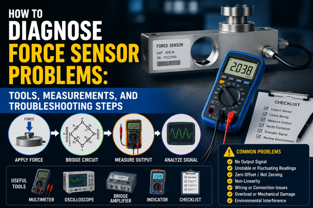
Common Force Sensor Fault Symptoms
Common problems include:
No signal
Signal stuck at zero
Signal stuck at maximum
Force value too high
Force value too low
Reading jumps randomly
Reading drifts over time
Zero does not return after unloading
Reading changes with temperature
Reading changes when cable is touched
PLC value does not match amplifier value
4–20 mA output stuck at 4 mA
4–20 mA output stuck at 20 mA
Output below 4 mA or above 20 mA
0–10V output stuck at 0V or 10V
Sensor overload alarm
Bridge error
Excitation error
Force reading is not repeatable
Different force reading during loading and unloading
Each symptom points to a different possible fault.
Tools Needed for Force Sensor Troubleshooting
1. Digital Multimeter
A multimeter is the first tool to use.
Use it to check:
24V DC power supply
Excitation voltage
Bridge resistance
Cable continuity
4–20 mA current
0–10V signal
Ground problems
Loose wiring
Short circuits
For many basic problems, a good multimeter is enough.
2. Loop Calibrator / Process Meter
A loop calibrator is very useful for 4–20 mA systems.
Use it to:
Measure the force sensor output current
Simulate 4–20 mA into the PLC input
Check PLC scaling
Check HMI scaling
Test whether the PLC input is working
If the amplifier value is correct but the PLC value is wrong, use a loop calibrator.
3. Strain Gauge Amplifier / Indicator
This is needed for raw mV/V force sensors.
A passive force sensor usually cannot connect directly to a normal PLC analog input.
A strain gauge amplifier provides:
Bridge excitation
Signal amplification
Filtering
Tare / zero function
Span setting
mV/V display
4–20 mA or 0–10V output
4. Precision Millivolt Meter
Raw force sensor signals are very small.
For example:
A 2 mV/V sensor with 10V excitation gives only 20 mV at full scale.
A normal multimeter may not be stable enough for accurate raw signal testing. A precision mV meter is better.
5. Insulation Tester
Use this carefully.
An insulation tester can help find:
Moisture in cable
Damaged cable insulation
Short to sensor body
Short to shield
Water inside connector
But do not test connected electronics.
Disconnect the sensor from the amplifier first and use only the test voltage allowed by the sensor manufacturer.
6. Oscilloscope
An oscilloscope is useful when the signal is noisy.
Use it to find:
Electrical spikes
VFD interference
Noise from contactors
Power supply ripple
Unstable amplifier output
Dynamic force signal problems
This is especially useful for fast force measurement.
7. Reference Load or Reference Force Sensor
To prove accuracy, you need a known load.
You can use:
Known weight
Reference load cell
Calibrated force sensor
Test press
Hydraulic pressure reference
Calibration fixture
Without a known load, you can check the electrical health, but you cannot fully prove measurement accuracy.
8. Torque Wrench
Mounting matters a lot.
Use a torque wrench to check:
Sensor mounting bolts
Load button mounting
Adapter plates
Rod ends
Compression plates
Tension fittings
Wrong tightening torque can cause bad repeatability or mechanical stress.
9. Dial Indicator or Mechanical Gauge
Useful for checking mechanical movement.
Sometimes the sensor is fine, but the machine frame, adapter, or fixture is moving incorrectly.
10. Temperature Meter
Use it when the reading drifts during operation.
Temperature can affect:
Sensor body
Strain gauges
Amplifier
Machine frame
Mounting surface
Cable
Step 1: Identify the Sensor Type
Before measuring, check what type of force sensor you have.
Common output types:
Raw mV/V bridge output
4–20 mA
0–10V
±10V
CAN
IO-Link
Modbus
PROFINET
EtherNet/IP
This matters because troubleshooting is different.
Passive mV/V Force Sensor
A passive force sensor has a raw strain gauge bridge.
Typical output:
0.5 mV/V
1.0 mV/V
2.0 mV/V
3.0 mV/V
It needs a bridge amplifier.
You must check:
Excitation voltage
Bridge resistance
Raw mV output
Cable condition
Amplifier settings
Active Force Sensor
An active force sensor has built-in electronics or an external amplifier.
Typical output:
4–20 mA
0–10V
±10V
Digital communication
You must check:
Power supply
Output signal
PLC scaling
Zero/tare
Span settings
Communication mapping
Step 2: Visual Inspection
Start with the simple things.
Check:
Is the sensor physically damaged?
Is the cable cut, crushed, or pulled?
Is the connector loose?
Is there oil or water inside the connector?
Are mounting bolts tight?
Is the sensor overloaded or bent?
Is the force applied in the correct direction?
Is there side load?
Is the load centered?
Is the contact surface flat and rigid?
Is the sensor installed according to the arrow or load direction mark?
Is the cable shield connected correctly?
Is the cable routed near motor or VFD cables?
Many force sensor problems are found during visual inspection.
Step 3: Check Mechanical Installation
A force sensor must be installed directly in the force flow.
This means the force must travel through the sensor body.
Good Installation
Force is centered
Load direction matches sensor design
Contact surface is flat
Mounting surface is rigid
Bolts are tightened correctly
No side load
No bending moment
No twisting force
Sensor range is suitable
Load adapter is aligned correctly
Bad Installation
Force is applied off-center
Sensor is mounted crooked
Load surface is soft or flexible
Sensor is side-loaded
Sensor is twisted
Bolts are loose
Fixture bends under load
Force bypasses the sensor
Sensor is too small for the load
Sensor has been overloaded
A force sensor can pass every electrical test and still measure wrong if the mechanical installation is bad.
Step 4: Check for Side Load and Bending
Force sensors are usually designed for a specific load direction.
For example:
Compression only
Tension only
Tension and compression
Shear
Bending
Torque
If the sensor is loaded in the wrong direction, the reading may be wrong or the sensor may be damaged.
Signs of Side Load Problems
Reading changes when fixture moves
Reading is not repeatable
Zero shifts after loading
Sensor output differs during loading and unloading
Force value changes when bolts are tightened
Sensor body shows mechanical damage
Reading is higher or lower than expected
Side load is one of the most common causes of inaccurate force measurement.
Step 5: Check Power Supply
For active sensors and amplifiers, measure power supply voltage.
Many industrial systems use 24V DC.
Good 24V DC Reading
For many industrial devices:
20.4V DC to 28.8V DC is usually acceptable.
This is 24V ±20%.
Always check the sensor or amplifier manual.
Bad Readings
0V
Wrong polarity
Below allowed voltage
Unstable voltage
Voltage drops during machine movement
High AC ripple
Loose 0V/common terminal
Power supply overloaded
Measure voltage at the device terminals while the sensor is connected.
A power supply can look good with no load but drop when connected.
Step 6: Check Excitation Voltage
For passive mV/V force sensors, the amplifier supplies bridge excitation.
Common excitation voltages:
2.5V
5V
10V
12V
Measure between excitation wires.
Common names:
EX+ and EX-
Exc+ and Exc-
Supply+ and Supply-
Bridge+ and Bridge-
Good Reading
Excitation voltage matches amplifier setting.
Examples:
5.00V if set to 5V
10.00V if set to 10V
Bad Reading
0V
Wrong voltage
Unstable voltage
Voltage changes when cable moves
Excitation shorted
Wrong wires connected
Amplifier not supplying excitation
Without stable excitation, the raw force sensor signal will not be correct.
Step 7: Check Bridge Resistance
Bridge resistance is one of the most important checks for passive strain gauge force sensors.
Common bridge resistance values:
120 Ω
350 Ω
700 Ω
1000 Ω
Many industrial sensors are 350 Ω, but not all.
Check the datasheet.
How to Measure
Disconnect the sensor from the amplifier.
Measure:
EX+ to EX-
SIG+ to SIG- if allowed by the manual
Individual bridge wires if the manufacturer gives a wiring diagram
Good Reading
Resistance close to datasheet value.
Examples:
350 Ω sensor reads around 350 Ω
1000 Ω sensor reads around 1000 Ω
A small tolerance is normal.
Bad Reading
OL / open circuit
Near 0 Ω
Very different from datasheet
Resistance jumps when cable moves
Short to shield
Short to sensor body
Different reading at connector and cable end
If bridge resistance is open, the strain gauge bridge or cable may be broken.
If resistance is near zero, there may be a short.
Step 8: Check Cable Continuity
Force sensor cables often fail because of movement, vibration, oil, pulling, or bad cable routing.
Check each wire from sensor connector to amplifier terminal.
Good Reading
Low resistance from end to end.
Usually:
Below 1–2 Ω for short cables
A few ohms may be normal for long cables
Bad Reading
Open wire
High resistance
Intermittent connection
Resistance jumps when cable is moved
Short between wires
Short to shield
Short to machine ground
Move the cable gently during the test. If the reading jumps, the cable or connector is likely damaged.
Step 9: Check Insulation Resistance
Insulation resistance testing can detect moisture and cable damage.
Important
Disconnect the sensor from the amplifier first.
Do not insulation-test PLC inputs, bridge amplifiers, or active sensor electronics.
Use the test voltage allowed by the manufacturer.
General Practical Values
| Insulation Resistance | Meaning |
|---|---|
| >100 MΩ | Very good |
| 20–100 MΩ | Usually acceptable, but check manual |
| 1–20 MΩ | Suspicious |
| <1 MΩ | Usually bad |
Low insulation can cause:
Zero drift
Noisy signal
Random jumps
Wrong force values
Temperature-dependent faults
Amplifier bridge errors
Water inside a connector is a common cause.
Step 10: Check Raw mV/V Signal
For passive force sensors, the raw output is very small.
Example:
Sensor sensitivity = 2 mV/V
Excitation voltage = 10V
Full-scale output:
2 × 10 = 20 mV
So:
0% force = around 0 mV
50% force = around 10 mV
100% force = around 20 mV
This assumes a simple unidirectional setup and correct zero.
Good Raw Signal
Stable zero
Signal changes smoothly with force
Signal returns to zero after unloading
Correct polarity
No random jumping
Output roughly matches expected mV/V range
Bad Raw Signal
No signal change under load
Signal jumps when cable is touched
Output saturated
Output reversed unexpectedly
Output does not return to zero
Large noise
Large zero offset
Signal drifts with no load
If raw mV signal is good but the PLC value is wrong, the problem is probably amplifier or PLC scaling.
Step 11: Check Zero Balance
Zero balance is the output when no force is applied.
Good Zero
Stable
Close to expected zero value
Returns after load is removed
Does not drift heavily
Within datasheet tolerance
Bad Zero
Large offset
Zero changes every cycle
Zero drifts over time
Zero changes when cable is moved
Zero changes when bolts are tightened
Zero does not return after unloading
Bad zero can be caused by:
Mechanical preload
Overload damage
Incorrect tare
Loose mounting
Bent fixture
Cable fault
Moisture
Bridge damage
Temperature drift
Step 12: Check 4–20 mA Output
Many force sensor amplifiers output 4–20 mA.
For a normal unidirectional force range:
| Force | Expected Current |
|---|---|
| 0% | 4 mA |
| 25% | 8 mA |
| 50% | 12 mA |
| 75% | 16 mA |
| 100% | 20 mA |
Example:
If the range is:
0–100 kN = 4–20 mA
Then:
0 kN = 4 mA
50 kN = 12 mA
100 kN = 20 mA
Good 4–20 mA Reading
Around 4 mA at zero force
Around 12 mA at half range
Around 20 mA at full range
Signal changes smoothly with force
PLC value matches measured current
Bad 4–20 mA Reading
| Reading | Possible Problem |
|---|---|
| 0 mA | Broken loop, no power, wrong wiring |
| Below 3.6 mA | Fault alarm on many devices |
| 4 mA all the time | No force, output stuck, wrong range, sensor not responding |
| 20 mA all the time | Overload, saturated output, wrong span |
| Above 21 mA | Overrange or fault alarm on many devices |
| Jumping signal | Noise, bad cable, loose wire, unstable load |
| Correct mA but wrong PLC value | PLC scaling problem |
Alarm currents vary by device, so check the amplifier configuration.
Step 13: Check 0–10V or ±10V Output
Some force amplifiers use voltage output.
For 0–10V:
| Force | Expected Voltage |
|---|---|
| 0% | 0V |
| 25% | 2.5V |
| 50% | 5V |
| 75% | 7.5V |
| 100% | 10V |
For ±10V:
-10V may represent full compression
0V may represent zero force
+10V may represent full tension
This depends on configuration.
Good Voltage Output
Stable voltage
Changes smoothly with force
Correct voltage for known load
Returns to zero after unloading
PLC value matches measured voltage
Bad Voltage Output
0V all the time
10V all the time
Negative value when not expected
Voltage drops when connected to PLC
Signal noisy
Signal changes when cable moves
PLC value does not match voltage
If voltage is correct before connecting to PLC but wrong after connection, check PLC input wiring, input impedance, and grounding.
Step 14: Compare Amplifier Value With PLC Value
This is a very important step.
Compare:
Amplifier display
Measured 4–20 mA or voltage
PLC raw analog value
PLC scaled force value
HMI displayed value
Example
Amplifier shows:
50 kN
Output range:
0–100 kN = 4–20 mA
Expected current:
12 mA
If you measure 12 mA but PLC shows 70 kN, the force sensor is probably not the problem.
The problem is likely:
PLC scaling
Wrong analog input range
HMI scaling
Wrong engineering units
Wrong channel
Wrong signal type
Step 15: Simulate the PLC Input
Use a loop calibrator or signal simulator.
For 4–20 mA:
| Simulated Signal | PLC Should Show |
|---|---|
| 4 mA | 0% |
| 8 mA | 25% |
| 12 mA | 50% |
| 16 mA | 75% |
| 20 mA | 100% |
For 0–10V:
| Simulated Signal | PLC Should Show |
|---|---|
| 0V | 0% |
| 2.5V | 25% |
| 5V | 50% |
| 7.5V | 75% |
| 10V | 100% |
If the PLC does not show the correct value, fix PLC scaling before replacing the sensor.
Step 16: Check Calibration
A force sensor must be calibrated correctly.
Factory calibration gives the sensor rating, but the full machine system may still need application calibration.
Good Calibration
Known force gives correct value
Zero is stable
Span is correct
Loading and unloading values are close
Calibration records match the installed sensor
PLC scaling matches amplifier range
Bad Calibration
Zero wrong
Span wrong
Reading correct at low force but wrong at high force
Reading not repeatable
Wrong unit used
Sensor replaced without updating calibration
Amplifier settings lost
PLC scaling copied from another machine
If the sensor or amplifier was replaced, always check calibration settings.
Step 17: Apply a Known Load
If possible, test the sensor with a known force.
Examples:
Known weight
Known press force
Calibrated reference load cell
Hydraulic cylinder with pressure reference
Test fixture
Simple Weight Example
A 100 kg mass creates approximately:
981 N
For rough checks, many people use:
100 kg ≈ 1000 N
If your sensor is measuring a small load range, known weights can be useful.
For large force sensors, use a proper calibration setup or reference sensor.
Good Result
Measured force matches known load within acceptable tolerance
Signal is repeatable
Zero returns after unloading
Bad Result
Measured force is far off
Reading changes each time
Zero shifts after load
Output is nonlinear
Sensor saturates too early
Step 18: Check Repeatability
Repeatability means the same force gives the same reading each time.
Test
Apply the same load several times.
Example:
Apply 10 kN five times.
Good
Reading returns close to the same value each time
Zero returns after unloading
Small variation only
Bad
Reading changes every cycle
Zero moves after each load
Output depends on speed
Force value depends on loading direction
Measurement becomes worse over time
Possible causes:
Loose mounting
Side load
Mechanical play
Sensor overload
Fixture bending
Cable movement
Bad calibration
Damaged sensor
Step 19: Check Hysteresis
Hysteresis means the reading is different during loading and unloading.
Example:
During loading at 50 kN, the sensor shows 50 kN.
During unloading at the same 50 kN point, it shows 47 kN.
Some hysteresis is normal, but too much is a problem.
Possible causes:
Mechanical friction
Bent fixture
Poor sensor mounting
Side loading
Sensor overload
Plastic deformation
Machine frame movement
Bad mechanical design
If hysteresis is large, do not only blame the sensor. Check the entire mechanical load path.
Step 20: Check for Overload Damage
Force sensors can be permanently damaged by overload.
Overload can cause:
Large zero offset
Output stuck high
Output not returning to zero
Poor repeatability
Permanent deformation
Cracked sensor body
Bridge damage
Broken cable strain relief
Signs of Overload
Sensor was used above rated force
Impact load occurred
Machine jammed
Zero changed after event
Calibration no longer valid
Sensor body visibly damaged
Output saturated
Known load test fails
If overload is suspected, compare the current zero and span with old maintenance records.
Step 21: Check Temperature Drift
Temperature can affect force measurement.
Temperature changes can cause:
Sensor body expansion
Strain gauge resistance changes
Amplifier drift
Fixture expansion
Mechanical preload changes
Good Behavior
Small drift within datasheet limits
Stable after warm-up
No sudden jumps
Temperature compensation working
Bad Behavior
Reading changes strongly as machine warms up
Zero drifts during the day
Force reading changes when ambient temperature changes
One side of sensor heated more than the other
Sensor near motor, heater, or hot hydraulic oil
A useful test is to record force reading and temperature over time.
If the force value follows temperature, the issue may be thermal drift, not real force change.
Step 22: Check Electrical Noise
Force sensor signals can be very small, especially raw mV/V signals.
Common noise sources:
VFD motor cables
Servo drives
Contactors
Solenoid valves
Welding machines
Poor grounding
Bad shield connection
Long signal cables
Unstable 24V power supply
Good
Stable signal
Shielded cable used
Cable routed away from power cables
No spikes when motors start
Amplifier grounded correctly
Bad
Signal jumps when VFD starts
Noise appears when contactor switches
Reading changes with motor speed
Cable routed next to motor cable
Shield disconnected
Signal noisy on oscilloscope
For passive mV/V sensors, shielding and cable routing are very important.
Step 23: Check Shielding and Grounding
Incorrect grounding can cause unstable force readings.
Check voltage between:
Sensor body and panel PE
Cable shield and panel PE
Machine frame and panel PE
Amplifier 0V and PE
Good
Ground difference close to 0V
Shield connected according to manual
No ground loop
Cable shield not used as signal common
Panel grounding is clean
Suspicious
More than about 1V AC or DC between grounding points
Shield connected at random places
Shield broken
High noise between machine frame and panel
Signal cable routed with power cables
Always follow the manufacturer’s grounding instructions because different systems may require different shield connections.
Step 24: Check Tare / Zero Function
Many amplifiers allow tare or zero adjustment.
This is useful, but it can also hide problems.
Good Use of Tare
Remove fixture weight
Set normal zero point
Compensate small installation offset
Document the tare condition
Bad Use of Tare
Taring while force is applied
Taring after overload to hide a fault
Taring with unstable machine
Wrong automatic tare logic
PLC tare command triggered at wrong time
If the force value suddenly becomes wrong, check whether someone changed the tare or zero setting.
Step 25: Check Dynamic Measurement Settings
If the force changes quickly, the sensor and amplifier must be fast enough.
Check:
Amplifier bandwidth
Filter settings
PLC sampling time
Analog input update time
HMI update rate
Data logging speed
Mechanical resonance
Cable shielding
Good
Fast enough response
No missed peaks
Signal is filtered but not too slow
PLC captures important force events
Bad
Force peak is missed
Signal looks delayed
Filter set too high
PLC scan too slow
HMI value looks lower than actual peak
Signal oscillates due to mechanical vibration
For press force monitoring or impact measurement, a slow analog setup can give misleading results.
Step 26: Check Digital Communication
Some force sensors or amplifiers use digital communication.
Common problems:
Wrong node address
Wrong IP address
Wrong register
Wrong byte order
Wrong data type
Wrong scaling factor
Wrong units
Status word read instead of force value
Communication timeout
Parameter set lost
Wrong device profile
If the local amplifier display is correct but the PLC value is wrong, communication mapping may be the problem.
Troubleshooting by Symptom
1. No Signal
Possible causes:
No power
No excitation voltage
Broken cable
Open bridge
Wrong wiring
Damaged amplifier
Wrong PLC channel
Checks:
Measure 24V supply
Measure excitation voltage
Check bridge resistance
Check cable continuity
Check amplifier status
Check PLC input wiring
2. Signal Stuck at Zero
Possible causes:
No force applied
Force bypassing the sensor
Sensor mounted incorrectly
Bridge fault
Amplifier zeroed incorrectly
PLC scaling wrong
Broken signal wire
Checks:
Apply known load safely
Check mechanical force path
Measure raw output
Check 4–20 mA or 0–10V
Check tare setting
Simulate PLC input
3. Signal Stuck at Maximum
Possible causes:
Overload
Sensor saturated
Wrong amplifier range
Shorted cable
Wrong calibration span
PLC scaling error
Bridge damage
Checks:
Remove load safely
Check zero
Measure output signal
Check bridge resistance
Check amplifier range
Check overload history
4. Reading Too High
Possible causes:
Wrong span
Wrong PLC scaling
Mechanical preload
Side load
Sensor range too small
Wrong units
Tare incorrect
Checks:
Check calibration
Compare amplifier and PLC value
Check mechanical mounting
Apply known load
Check zero/tare
5. Reading Too Low
Possible causes:
Force not fully passing through sensor
Loose mounting
Fixture bending
Wrong calibration
Amplifier gain too low
PLC range too large
Sensor installed in wrong position
Checks:
Check force path
Check mounting bolts
Apply known load
Measure output signal
Check amplifier and PLC scaling
6. Reading Unstable
Possible causes:
Loose connector
Cable damage
Electrical noise
Mechanical vibration
Side load
Loose mounting
Unstable power supply
Poor grounding
Checks:
Move cable gently while watching signal
Check shield
Check oscilloscope noise
Check power supply
Check mounting
Check machine vibration
7. Zero Drifts
Possible causes:
Temperature change
Sensor overload
Moisture
Mechanical stress
Tare problem
Amplifier drift
Fixture relaxation
Checks:
Record temperature
Check insulation resistance
Check zero after unloading
Check mounting
Check tare settings
Check for overload history
8. PLC Value Wrong but Amplifier Correct
Possible causes:
PLC scaling error
Wrong analog input setting
Wrong HMI scaling
Wrong signal type
Wrong communication register
Wrong engineering unit
Checks:
Measure output mA or voltage
Simulate PLC input
Check PLC raw value
Check HMI tag scaling
Check fieldbus mapping
Quick Measurement Table
| Test | Good Measurement | Bad Measurement |
|---|---|---|
| 24V DC supply | Usually 20.4–28.8V DC | Missing, low, unstable, reversed |
| Excitation voltage | Matches amplifier setting, often 5V or 10V | 0V, wrong, unstable |
| Bridge resistance | Close to datasheet, often 120Ω/350Ω/1000Ω | OL, near 0Ω, unstable |
| Cable continuity | Low resistance end-to-end | Open, high resistance, intermittent |
| Insulation resistance | >100 MΩ very good | <1 MΩ usually bad |
| Raw mV/V output | Smooth proportional signal | No change, noisy, saturated |
| 4–20 mA at 0% | Around 4 mA | 0 mA, alarm current, unstable |
| 4–20 mA at 50% | Around 12 mA | Wrong current for known load |
| 4–20 mA at 100% | Around 20 mA | Saturated, wrong scaling |
| 0–10V at 50% | Around 5V | Wrong voltage, unstable |
| Ground difference | Close to 0V | More than 1V suspicious |
| Known load test | Correct and repeatable | Wrong, drifting, non-repeatable |
| Zero return | Returns after unloading | Permanent offset or drift |
| Repeatability | Same load gives similar value | Different value every cycle |
What Measurements Are Usually Good?
These are general practical values:
24V DC supply around 20.4–28.8V DC
Stable excitation voltage, commonly 5V or 10V
Bridge resistance close to datasheet value
Common bridge values: 120Ω, 350Ω, 700Ω, 1000Ω
Insulation resistance above 100 MΩ is very good
4 mA at zero force for normal 4–20 mA setup
12 mA at 50% of configured range
20 mA at 100% of configured range
0V at zero force for normal 0–10V setup
5V at 50% range
10V at 100% range
Raw full-scale output close to rated mV/V value
Stable zero after warm-up
Repeatable value under repeated known load
PLC value matching measured signal after scaling
What Measurements Are Usually Bad?
These readings usually indicate a problem:
0V supply
24V supply below allowed range
Wrong polarity
No excitation voltage
Unstable excitation voltage
Bridge resistance open circuit
Bridge resistance near 0Ω
Bridge resistance far from datasheet
Insulation resistance below 1 MΩ
4–20 mA output at 0 mA
Output below 3.6 mA or above 21 mA without explanation
Signal stuck at 4 mA while force is changing
Signal stuck at 20 mA with normal force
0–10V output stuck at 0V or 10V
Raw mV signal does not change under load
Zero offset changes every cycle
Reading jumps when cable is touched
Reading changes when VFD starts
Known load test is not repeatable
PLC value does not match measured mA or voltage
Practical Diagnostic Order
When diagnosing a force sensor, I would follow this order:
- Identify the sensor output type.
- Check sensor, amplifier, PLC, and HMI alarms.
- Visually inspect sensor, cable, connector, and mounting.
- Check if the force passes correctly through the sensor.
- Check for side load, bending, and incorrect alignment.
- Measure power supply voltage.
- For passive sensors, measure excitation voltage.
- Measure bridge resistance with the sensor disconnected.
- Check cable continuity.
- Check insulation resistance if allowed.
- Check zero balance.
- Apply a known load safely.
- Measure raw mV/V, 4–20 mA, or 0–10V output.
- Compare amplifier value with PLC value.
- Simulate PLC input.
- Check calibration, tare, and span.
- Check repeatability and hysteresis.
- Check for overload damage.
- Check temperature drift.
- Check electrical noise, shielding, and grounding.
- Check digital communication mapping if used.
This order helps prevent unnecessary sensor replacement.
Final Thoughts
Force sensor troubleshooting is not only about electrical measurements.
A force sensor can fail electrically, but it can also give wrong readings because the mechanical load is applied incorrectly.
The most important things to check are:
Power supply
Excitation voltage
Bridge resistance
Raw mV/V signal
4–20 mA or 0–10V output
PLC scaling
Mechanical mounting
Force direction
Side loading
Calibration
Repeatability
Temperature drift
Electrical noise
The key rule is simple:
If the force is not applied correctly through the sensor, the measurement will not be reliable.
If the raw sensor signal is correct but the PLC value is wrong, check scaling.
If the electrical signal is unstable, check wiring, grounding, shielding, and power supply.
If the electrical signal is good but the force value is wrong, check mounting, calibration, and the mechanical force path.