A force sensor is a device used to measure mechanical force.
In industrial automation, force sensors are used when a machine needs to know how much force is being applied during a process.
They are common in:
Press machines
Clamping systems
Assembly machines
Testing machines
Robotics
Packaging machines
Material testing
Weighing systems
Tension and compression measurement
Process monitoring
Machine protection
The basic idea is simple:
A force is applied to the sensor.
The sensor body deforms slightly.
Strain gauges detect this deformation.
The sensor converts it into an electrical signal.
That signal can then be used by a PLC, controller, display, amplifier, or data acquisition system.
How Do You Measure Force?
To measure force correctly, the force sensor must be installed in the correct position.
The most important rule is:
The force must pass through the sensor.
This is called placing the sensor directly in the force flow.
For example, if you want to measure compression force, the force sensor should be installed between the two parts that are pressing against each other.
If you want to measure tension force, the force sensor must be connected so that the pulling force goes through the sensor.
Good force measurement depends on:
Correct sensor position
Centered force application
Rigid mounting surface
Correct mechanical alignment
Correct load direction
No side loading
No twisting moment
Correct calibration
Correct amplifier or PLC scaling
If the force does not pass properly through the sensor, the measurement will be wrong.
Force Sensor vs Strain Sensor
A force sensor measures force directly.
A strain sensor usually measures force indirectly.
This is an important difference.
Force Sensor
A force sensor is installed directly in the force path.
The force flows through the sensor body.
This gives a direct force measurement.
Use a force sensor when:
You can place the sensor directly in the force path
You need accurate force measurement
The mechanical design allows sensor installation
The force direction is clear
You want a calibrated output in Newtons or kilonewtons
Strain Sensor
A strain sensor is mounted on the surface of a machine structure.
It measures how much the structure deforms.
The force is then estimated from that deformation.
Use a strain sensor when:
The force is very large
The machine structure already carries the load
There is no space for a force sensor
You want to monitor an existing machine
You want indirect force measurement
Changing the machine design is difficult
In simple words:
A force sensor measures force directly.
A strain sensor measures deformation and uses it to estimate force.
How Does a Force Sensor Work?
Many industrial force sensors are based on strain gauge technology.
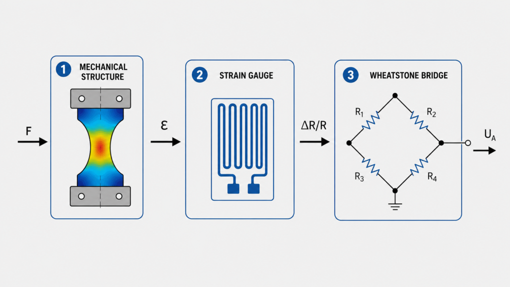
A strain gauge-based force sensor works in three main steps:
Mechanical force creates deformation.
Strain gauges convert deformation into resistance change.
Electronics convert the resistance change into a usable output signal.
The deformation is very small. You usually cannot see it with your eyes.
But the strain gauges can detect it.
Step 1: Force Deforms the Sensor Body
The force sensor has a specially designed metal body.
This body is sometimes called the spring element, measuring body, or mechanical converter.
When force is applied, the metal body bends, stretches, or compresses slightly.
This deformation must stay inside the elastic range of the material.
That means:
When the force is removed, the sensor body returns to its original shape.
If the sensor body is overloaded beyond its elastic limit, it may be permanently deformed and the sensor may no longer measure correctly.
Step 2: Strain Gauges Detect the Deformation
Strain gauges are attached to the sensor body in carefully selected areas.
When the sensor body deforms, the strain gauges deform too.
A strain gauge is a small electrical element that changes resistance when stretched or compressed.
This resistance change is very small, but it is proportional to the deformation.
Because the deformation is related to the applied force, the resistance change can be used to measure force.
Step 3: The Signal Is Converted Into an Output
The strain gauges are connected in a Wheatstone bridge circuit.
This bridge circuit converts tiny resistance changes into a small voltage signal.
The signal is often very small, usually in the range of:
0.4 to 3.0 mV/V
Because this signal is so small, it usually needs a bridge amplifier.
The amplifier converts the raw bridge signal into something easier to use, such as:
4–20 mA
0–10V
±10V
CAN
IO-Link
Digital output
PLC analog signal
Main Parts of a Force Sensor
A typical strain gauge-based force sensor includes:
Sensor body
Strain gauges
Wheatstone bridge circuit
Cable or connector
Optional amplifier electronics
Protective housing or sealing
Let’s look at each part.
1. Sensor Body
The sensor body is the mechanical part that receives the force.
It must be designed carefully.
It needs to deform enough for accurate measurement, but not so much that it is damaged.
This is a balancing act.
If the sensor body is too stiff, the strain signal is very small.
If the sensor body is too weak, it may overload or fatigue too quickly.
Good force sensor design tries to create a controlled deformation zone where the strain gauges can measure reliably.
Sensor Body Materials
Force sensors are often made from strong metals such as:
Stainless steel
Tempered steel
Tool steel
Aluminum
Special metallic alloys
The material choice depends on:
Force range
Environment
Corrosion resistance
Fatigue life
Temperature range
Size requirements
Cost
Hygiene requirements
Stainless steel is common because it is strong, stable, and corrosion-resistant.
Aluminum may be used for lighter or lower-force sensors.
2. Strain Gauges
Strain gauges are the core measuring elements inside many force sensors.
A typical strain gauge has:
A thin carrier film
A fine metal measuring grid
A protective top layer
The measuring grid is often arranged in a zigzag shape.
When the sensor body stretches or compresses, the grid changes shape slightly.
That changes its electrical resistance.
This resistance change is the first electrical sign that force has been applied.
Gauge Factor / K-Factor
The sensitivity of a strain gauge is described by the gauge factor, also called the K-factor.
The K-factor describes the relationship between mechanical strain and resistance change.
A common K-factor for metallic strain gauges is around:
2.0 to 2.1
For example, a constantan strain gauge may have a K-factor close to 2.05.
The exact value depends on the strain gauge type and material.
3. Wheatstone Bridge Circuit
A Wheatstone bridge is an electrical circuit used to measure very small resistance changes.
In force sensors, four strain gauges are often connected into a full bridge.
The bridge has two voltage dividers connected in parallel.
It is supplied by a stable excitation voltage.
When no force is applied, the bridge is balanced.
When force is applied, some strain gauges stretch and some compress.
This changes their resistance and creates a small bridge output voltage.
That voltage is proportional to the applied force.
Why Use a Wheatstone Bridge?
A strain gauge resistance change is tiny.
The Wheatstone bridge makes it possible to detect these tiny changes accurately.
It also helps with:
Temperature compensation
Better sensitivity
Improved linearity
Noise reduction
Stable measurement
Positive and negative force measurement
In many bending beam or diaphragm force sensors, two gauges are loaded in tension and two gauges are loaded in compression.
This improves signal strength and helps cancel unwanted effects.
4. Bridge Amplifier
The raw signal from a strain gauge bridge is very small.
For example, a sensor with 2 mV/V sensitivity and 10V excitation gives only:
20 mV at full scale
That is too small for most standard PLC analog inputs.
A bridge amplifier solves this problem.
It does two things:
Supplies the Wheatstone bridge with stable excitation voltage.
Amplifies the tiny bridge signal into a usable output.
Common amplifier outputs include:
4–20 mA
0–10V
±10V
Digital communication
IO-Link
CAN
Bridge amplifiers also often allow:
Tare / zero adjustment
Span adjustment
Filtering
Calibration
Signal diagnostics
Overload monitoring
The tare function is especially useful because it allows the system to remove small zero offsets caused by installation.
How to Calculate Force
Force is measured in Newtons, symbol N.
The basic formula is:
F = m × a
Where:
F = force in Newtons
m = mass in kilograms
a = acceleration in m/s²
For weight force on Earth, acceleration is gravity:
g ≈ 9.81 m/s²
In practical rough calculations, people often use:
g ≈ 10 m/s²
So a 100 kg mass creates approximately:
F = 100 × 10 = 1000 N
More accurately:
F = 100 × 9.81 = 981 N
So:
100 kg is roughly equal to 1 kN of force due to gravity.
What Is Strain?
When force is applied to a body, the body changes shape slightly.
If it is pulled, it stretches.
If it is compressed, it shortens.
This relative change in length is called strain.
The formula is:
ε = ΔL / L₀
Where:
ε = strain
ΔL = change in length
L₀ = original length
Strain has no dimension because it is a ratio.
In industrial measurement, strain is usually very small, so it is often shown as:
µm/m
or
µε
For example:
500 µm/m means the material changes length by 500 micrometers per meter.
From Force to Strain
When a force is applied to a component, the component experiences stress and strain.
Stress is force divided by area:
σ = F / A
Where:
σ = stress
F = force
A = cross-sectional area
In the elastic range of a material, stress and strain are related by Hooke’s Law:
σ = E × ε
Where:
E = modulus of elasticity / Young’s modulus
ε = strain
If we combine the equations:
F / A = E × ε
So:
F = A × E × ε
This means force can be related to strain if we know:
Material stiffness
Cross-sectional area
Measured strain
Modulus of Elasticity
The modulus of elasticity describes how stiff a material is.
A stiff material has a high modulus.
A flexible material has a low modulus.
Typical values:
Steel: about 200,000 to 210,000 N/mm²
Aluminum: about 70,000 N/mm²
This means aluminum deforms more than steel under the same force and geometry.
Simple Force Calculation Example
Imagine a steel part with:
Cross-sectional area: 400 mm²
Elastic modulus: 210,000 N/mm²
Measured strain: 240 µm/m
Convert strain:
240 µm/m = 240 × 10⁻⁶
Use the formula:
F = A × E × ε
Calculation:
F = 400 × 210,000 × 240 × 10⁻⁶
F = 20,160 N
So the force is approximately:
20.16 kN
This is a simplified example.
Real force sensors are calibrated by the manufacturer, so normally you use the sensor output and calibration data rather than calculating force manually every time.
Common Force Sensor Designs
Force sensors can be built in different mechanical shapes.
The design depends on the force direction, force range, accuracy, size, and environment.
Common types include:
Diaphragm force sensors
S-beam force sensors
Cylindrical force sensors
Bending beam force sensors
Compression force sensors
Tension force sensors
Load pins
Ring force sensors
Button force sensors
Diaphragm Force Sensors
Diaphragm force sensors use a thin diaphragm-shaped measuring body.
They can be compact and easy to seal.
They are often used where small size and environmental protection matter.
Advantages:
Compact design
Good sealing possible
Suitable for harsh environments
Can be cost-effective
Useful for compression force
S-Beam Force Sensors
S-beam sensors are commonly used for tension and compression.
They are shaped like the letter S.
They are often used in:
Hanging scales
Material testing
Tension measurement
Compression measurement
Test benches
Bending Beam Force Sensors
Bending beam sensors measure force by controlled bending of the sensor body.
They are common in weighing and industrial force measurement.
They are useful for:
Platform scales
Small tanks
Process weighing
Force measurement fixtures
Cylindrical Force Sensors
Cylindrical sensors are often used for compression force.
They are strong and compact.
They may be used in:
Press applications
Clamping systems
Machine force monitoring
Heavy industrial force measurement
Force Sensor Accuracy
Force sensor accuracy depends on several characteristics.
Important terms include:
Linearity
Hysteresis
Repeatability
Creep
Temperature drift
Zero balance
Sensitivity
Overload capacity
Fatigue strength
Linearity
Linearity describes how close the sensor output is to a straight line.
A good force sensor should have an output that changes proportionally with force.
Example:
25% force = 25% output
50% force = 50% output
100% force = 100% output
Hysteresis
Hysteresis means the sensor output may be slightly different when force is increasing compared with when force is decreasing.
Example:
At 50 kN during loading, the sensor shows one value.
At 50 kN during unloading, it may show a slightly different value.
Lower hysteresis is better.
Repeatability
Repeatability means the sensor gives the same result when the same force is applied multiple times.
Good repeatability is important in production machines.
Creep
Creep means the sensor output slowly changes while the same force remains applied.
This matters when a load is held for a long time.
Temperature Drift
Temperature changes can affect both the sensor body and strain gauges.
Good force sensors use strain gauge selection and bridge design to reduce temperature effects.
Still, temperature must be considered in accurate measurements.
Temperature Effects in Force Sensors
Temperature changes can create expansion in the sensor body.
For example, a steel part can change length when temperature changes.
Even a small temperature change can create measurable strain.
That is why force sensors are designed with temperature compensation.
Temperature compensation is usually achieved by:
Choosing suitable strain gauge materials
Matching strain gauge expansion behavior
Using Wheatstone bridge arrangements
Using compensation circuits
Using amplifier correction
Calibrating over temperature
Even with compensation, avoid unnecessary temperature gradients.
For example, do not heat only one side of the sensor if accurate measurement is required.
Fatigue Strength and Dynamic Loads
Many force sensors are used in machines that apply force repeatedly.
Examples:
Press cycles
Clamping cycles
Testing cycles
Vibration
Impact loading
Dynamic process forces
A good force sensor must survive repeated loading within its rated range.
Fatigue strength depends on:
Sensor body material
Mechanical design
Force range
Load direction
Overload events
Vibration
Mounting quality
Environmental conditions
Some sensors are designed for more than one million load cycles at nominal force, but the actual rating depends on the sensor model.
Always check the datasheet.
Static and Dynamic Force Measurement
Force sensors can measure both static and dynamic loads, depending on design and electronics.
Static Force
Static force changes slowly or remains constant.
Examples:
Holding force
Clamping force
Weight force
Slow press force
Tank load
Dynamic Force
Dynamic force changes quickly.
Examples:
Impact force
Pressing cycle
Vibration
Fast assembly process
Machine testing
High-speed clamping
For dynamic measurement, check:
Sensor frequency response
Amplifier bandwidth
Sampling rate
Mechanical mounting
Cable shielding
Signal filtering
A slow amplifier can hide fast force changes.
Force Sensor Output Signals
Force sensors can provide different output types.
mV/V Output
This is the raw strain gauge bridge signal.
Example:
2 mV/V
This means the sensor gives 2 mV output per volt of excitation at full scale.
If excitation is 10V:
2 mV/V × 10V = 20 mV full-scale output
This signal needs a bridge amplifier.
4–20 mA Output
This is common in industrial automation.
Example:
4 mA = 0 kN
20 mA = 100 kN
Advantages:
Good for long cables
Common for PLC analog inputs
Less sensitive to voltage drop
Good noise immunity
0–10V or ±10V Output
Voltage outputs are also common.
Example:
0V = 0 kN
10V = 100 kN
A ±10V output is useful for tension and compression measurement.
Example:
-10V = full compression
0V = zero force
+10V = full tension
Digital Output
Some force sensors or amplifiers provide digital communication such as:
IO-Link
CANopen
Modbus
PROFINET
EtherNet/IP
Digital outputs can provide:
Force value
Status
Diagnostics
Overload warning
Temperature information
Parameter settings
Force Sensors and PLC Systems
In automation, force sensors are often connected to a PLC.
A simple setup may look like this:
Force sensor is installed in the machine.
Force is applied through the sensor.
Sensor output goes to amplifier.
Amplifier sends 4–20 mA to PLC.
PLC scales signal into Newtons or kilonewtons.
HMI displays force value.
PLC uses force for alarms or control.
Example scaling:
4 mA = 0 kN
20 mA = 50 kN
Then:
12 mA = 25 kN
The PLC can use the force value for:
Overload protection
Process control
Quality checks
Press force monitoring
Clamping force control
Reject detection
Machine diagnostics
Force Sensors vs Load Cells
Force sensors and load cells are very similar physically.
Both often use strain gauges.
The main difference is usually calibration and application.
A force sensor is usually calibrated in force units:
Newtons
Kilonewtons
A load cell is often calibrated in weight or mass-related units:
Grams
Kilograms
Tonnes
Physically, the sensor technology can be almost the same.
The difference is how the measurement is used and calibrated.
In simple terms:
Force sensor = force measurement in N or kN
Load cell = weight measurement in kg or tonnes
Advantages of Strain Gauge-Based Force Sensors
Strain gauge force sensors are widely used because they offer many advantages.
1. Proven Technology
Strain gauge force measurement has been used for a long time and is well understood.
2. Good Accuracy
With correct design and calibration, force sensors can provide accurate measurements.
3. Good Linearity and Hysteresis
High-quality sensors can give stable and predictable output.
4. Temperature Compensation
Wheatstone bridge design helps reduce temperature effects.
5. Static and Dynamic Measurement
They can be used for slow loads and many dynamic force applications.
6. Good Long-Term Stability
When installed correctly and not overloaded, force sensors can remain stable for long periods.
7. High Fatigue Strength
Correct materials and design allow repeated load cycles.
8. Easy PLC Integration
With the right amplifier, force sensors can be connected easily to PLC systems.
Limitations of Force Sensors
Force sensors are useful, but they must be applied correctly.
Common limitations include:
They can be damaged by overload
Side loads can cause measurement errors
Mounting surface must be rigid
Force must be centered
Temperature can affect measurement
Incorrect installation causes wrong readings
Raw mV/V signals need amplification
Calibration may be required
Dynamic loads require suitable electronics
A force sensor is only accurate if the mechanical installation is correct.
Installation Tips for Force Sensors
Good installation is extremely important.
Follow these rules:
Apply force centrally.
Avoid side loading.
Avoid bending moments unless the sensor is designed for them.
Use rigid mounting surfaces.
Use correct mounting screws.
Use the correct torque.
Keep contact surfaces clean and flat.
Align the force direction correctly.
Protect the cable from pulling.
Do not exceed overload limits.
Do not weld near the sensor unless allowed.
Avoid strong temperature gradients.
Use shielded cable for low-level signals.
Most force sensor problems come from bad installation, not from the sensor itself.
Example: Measuring Press Force
Imagine a small press machine.
You want to measure how much force is applied during the pressing operation.
A compression force sensor is installed between the press ram and the tool.
When the press moves down, the force passes through the sensor.
The sensor body deforms slightly.
The strain gauges detect the deformation.
The bridge amplifier converts the signal to 4–20 mA.
The PLC reads the signal and scales it:
4 mA = 0 kN
20 mA = 100 kN
The HMI displays the live force.
The PLC can trigger an alarm if force is too high or too low.
This is a direct force measurement application.
How to Choose a Force Sensor
Before choosing a force sensor, check:
Force range
Tension or compression
Static or dynamic load
Accuracy requirement
Mounting method
Available space
Overload capacity
Environmental protection
Material
Temperature range
Output signal
Need for amplifier
PLC compatibility
Calibration requirement
Cable or connector type
Fatigue life
Side load sensitivity
Certification requirements
For industrial automation, also check:
Does the PLC need 4–20 mA or 0–10V?
Is the load constant or dynamic?
Will the sensor see vibration?
Can the force be applied centrally?
Is the mounting surface stiff enough?
Does the application require a safety-rated solution?
Final Thoughts
A force sensor measures mechanical force by converting deformation into an electrical signal.
In many industrial force sensors, the measuring principle is based on strain gauges.
The process is:
Force enters the sensor body.
The sensor body deforms elastically.
Strain gauges detect this deformation.
The Wheatstone bridge creates a small voltage signal.
The amplifier converts the signal into a PLC-friendly output.
The most important thing to remember is:
A force sensor must be installed directly in the force flow.
If the force is not applied correctly, the measurement will not be reliable.
Force sensors are useful for press force monitoring, clamping force measurement, material testing, automation feedback, overload protection, and quality control.
For PLC and automation work, they are a great example of how mechanical design, electrical measurement, and control systems work together.