Some machines don’t just need a motor to start and stop.
They need it to move one way, then the other.
A conveyor may need forward and reverse. A crane may need left and right travel. A hoist may need up and down motion. A gate, screw conveyor, winch, or positioning system may need clockwise and counterclockwise rotation. In all these cases, the basic idea is the same: the motor must be able to rotate in two directions.
For a three-phase motor, this is usually done by swapping two phases.
Simple in theory.
Very serious in wiring.
Because if both directions are energized at the same time, even for a moment, you can create a direct phase-to-phase short circuit. That is why forward-reverse motor control must always include proper interlocking.
What Is Motor Rotation Inversion?
Motor rotation inversion means changing the direction of rotation of an electric motor.
For a three-phase induction motor, the rotation direction depends on the phase sequence supplied to the motor terminals. If the motor receives the phases in one order, it rotates in one direction. If two phases are swapped, the motor rotates in the opposite direction.
For example:
- R, S, T = clockwise rotation
- T, S, R = counterclockwise rotation
The exact direction depends on the motor and machine arrangement, but the principle is the same. Reversing any two phases reverses the rotation direction.
This is the foundation of a forward-reverse motor starter.
Power Circuit of a Forward-Reverse Motor
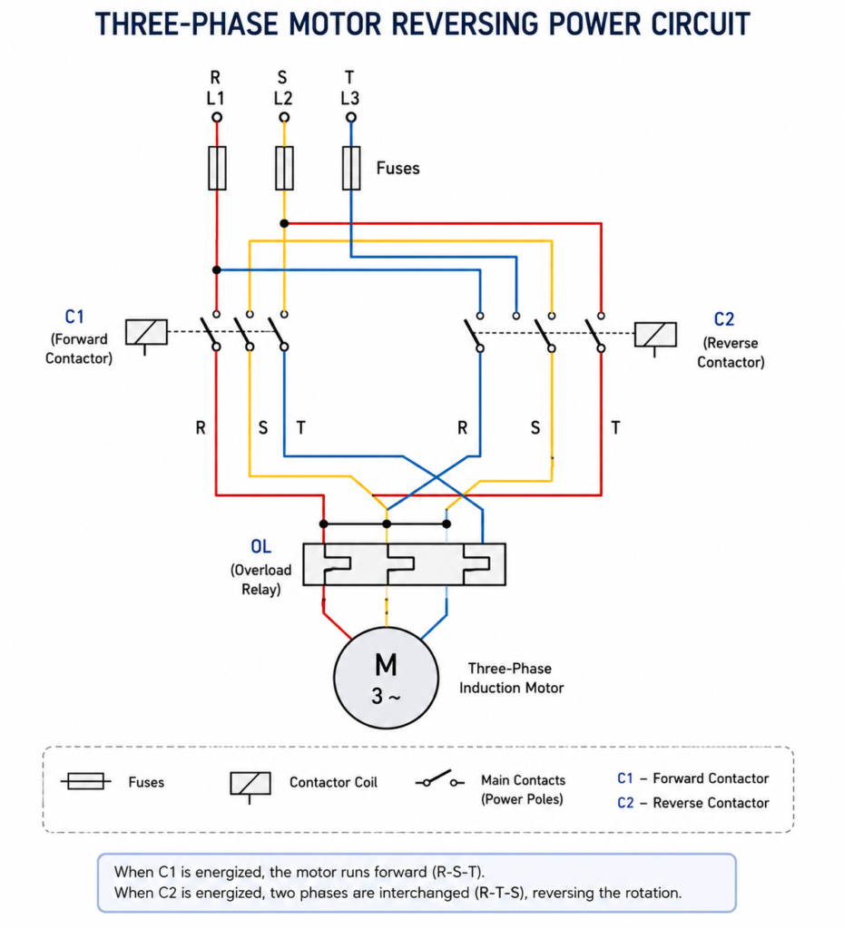
A motor with two rotation directions normally uses two contactors.
One contactor is used for clockwise rotation. The other contactor is used for counterclockwise rotation.
Let’s call them:
- C1 = clockwise contactor
- C2 = counterclockwise contactor
When contactor C1 is energized, the motor is connected to the three-phase supply in the normal phase order.
For example:
- Motor terminal U receives phase R
- Motor terminal V receives phase S
- Motor terminal W receives phase T
The motor rotates clockwise.
When contactor C2 is energized, two phases are swapped.
For example:
- Motor terminal U receives phase T
- Motor terminal V receives phase S
- Motor terminal W receives phase R
The motor rotates counterclockwise.
So the two contactors do not simply turn the motor on and off. They choose the direction by changing the phase sequence.
Why Interlocking Is Critical
The most important rule in a forward-reverse motor circuit is this:
C1 and C2 must never be energized at the same time.
If both contactors close together, the circuit may directly short two phases. This can damage contactors, blow fuses, trip breakers, weld contacts, damage wiring, and create a dangerous arc fault.
Not “maybe bad.”
Definitely bad.
That is why forward-reverse circuits always need mutual exclusion, also called interlocking.
There are usually two types of interlocking:
- Electrical interlocking
- Mechanical interlocking
Both are important.
Electrical Interlocking
Electrical interlocking uses auxiliary contacts to prevent one contactor from energizing while the other one is already active.
For example, the normally closed auxiliary contact of C2 is placed in series with the coil of C1. If C2 is energized, its NC contact opens and blocks C1 from turning on.
The same is done in the opposite direction. The normally closed auxiliary contact of C1 is placed in series with the coil of C2. If C1 is energized, C2 is blocked.
This gives the logic:
- If C1 is on, C2 cannot start
- If C2 is on, C1 cannot start
That is electrical protection against simultaneous operation.
Mechanical Interlocking
Mechanical interlocking is a physical mechanism between the two contactors.
It prevents both contactors from closing at the same time, even if there is an electrical fault or wiring mistake.
This is very important because electrical contacts can fail. Auxiliary contacts can be wired incorrectly. A control relay can stick. Someone can make a mistake during panel modification.
A mechanical interlock gives another layer of protection.
For a real forward-reverse starter, using both electrical and mechanical interlocking is good practice.
Because phase-to-phase short circuits are not something you want to “test.”
Manual Control Buttons
A typical manual forward-reverse motor control circuit uses three push buttons:
- START CW for clockwise rotation
- START CCW for counterclockwise rotation
- STOP to stop the motor
The STOP button is usually normally closed and placed in series with both contactor coil circuits.
The START buttons are normally open. Pressing START CW energizes contactor C1. Pressing START CCW energizes contactor C2.
In a maintained operation circuit, each direction contactor also has its own self-latching auxiliary contact. This allows the motor to continue running after the START button is released.
So the operator presses START CW once, and the motor keeps rotating clockwise until STOP is pressed.
Same for counterclockwise operation.
Forward-Reverse Circuit With Latching
In a permanent or maintained forward-reverse circuit, the motor keeps running in the selected direction after the operator releases the start button.
The clockwise branch usually contains:
- STOP button NC contact
- Thermal overload NC contact
- C2 normally closed interlock contact
- START CW button
- C1 self-latching NO contact
- C1 coil
The counterclockwise branch contains:
- STOP button NC contact
- Thermal overload NC contact
- C1 normally closed interlock contact
- START CCW button
- C2 self-latching NO contact
- C2 coil
When START CW is pressed, C1 energizes. Its main contacts power the motor in clockwise phase order. Its auxiliary NO contact closes and holds the circuit on. Its NC interlock contact in the opposite branch opens, preventing C2 from energizing.
When STOP is pressed, C1 de-energizes, the motor stops, and the latch opens.
Only after stopping can the operator press START CCW to run the motor in the opposite direction.
This is important: in this circuit, direction cannot be changed directly while the motor is running. The motor must be stopped first.
That is usually safer for the motor, gearbox, load, and machine mechanics.
Why the Motor Must Stop Before Reversing
Changing direction while a motor is running can create high mechanical and electrical stress.
The motor has inertia. The load has inertia too. If the motor is suddenly commanded in the opposite direction, it may draw a very high current and create strong mechanical shock.
For some machines, this is unacceptable.
Examples include:
- Conveyors with heavy loads
- Gearboxes
- Pumps
- Fans
- Screw conveyors
- Mixers
- Rollers
- Large mechanical drives
For these machines, the control circuit should require STOP before changing direction.
In other words:
Run clockwise.
Press STOP.
Wait for stopping if required.
Then start counterclockwise.
It sounds slow, but it protects the machine.
Thermal Overload Protection
A forward-reverse motor circuit should include motor overload protection.
A thermal overload relay is usually placed after the contactors in the power circuit, before the motor. Its normally closed auxiliary contact is wired in the control circuit, usually in series with both contactor coils.
If the motor draws too much current for too long, the overload relay trips. Its NC contact opens. This breaks the control circuit and de-energizes whichever contactor is active.
The motor stops.
This protects the motor from overload conditions such as:
- Jammed load
- Mechanical blockage
- Phase loss
- Bearing problems
- Overloaded conveyor
- Motor running above rated current
- Too frequent starting
In a forward-reverse starter, the overload protection should stop both directions. It should not protect only one branch.
One overload contact. Both direction circuits blocked.
Direction Indicator Lamps
Many forward-reverse circuits include indicator lamps.
For example:
- Green lamp for clockwise running
- Yellow or blue lamp for counterclockwise running
- Red lamp for fault or overload trip
The direction lamps are usually controlled by auxiliary contacts from the contactors.
When C1 is energized, the CW lamp turns on.
When C2 is energized, the CCW lamp turns on.
This gives the operator a clear visual indication of the active direction.
It also helps during troubleshooting. If the contactor is energized but the lamp is not on, you may have an auxiliary contact or lamp circuit issue. If the lamp is on but the motor is not moving, the problem may be in the power circuit, overload, motor, or mechanical load.
A small lamp can save time. Old trick, still useful.
Instant Operation Forward-Reverse Circuit
Not every forward-reverse circuit uses latching.
In some machines, the motor should run only while the operator holds the direction button. This is called instant operation or momentary operation.
A crane is a good example.
The operator presses and holds the button for movement. The motor runs. When the operator releases the button, the motor stops.
In this type of circuit, there is no self-latching contact. The START CW and START CCW buttons directly energize their contactor coils only while pressed, with proper interlocking still included.
This is useful for:
- Cranes
- Hoists
- Jogs
- Positioning movements
- Setup mode
- Manual inching
- Maintenance movement
The logic is simple:
Hold button = movement.
Release button = stop.
For some machines, that is exactly what you want.
Maintained Operation vs Instant Operation
The difference between maintained and instant operation is important.
Maintained operation means the motor continues running after the start button is released. This is common for conveyors, pumps, fans, and production machines.
Instant operation means the motor runs only while the button is pressed. This is common for cranes, hoists, jog circuits, and manual positioning.
Comparison:
| Feature | Maintained Forward-Reverse | Instant Forward-Reverse |
|---|---|---|
| Uses latching | Yes | No |
| Motor runs after button release | Yes | No |
| Requires STOP button | Yes | Often yes, but release may stop movement |
| Common use | Conveyors, machines, pumps | Cranes, hoists, jog movement |
| Direction change | Usually stop first | Operator releases one button first |
| Control style | Start-stop memory | Hold-to-run |
Both are correct.
The right choice depends on the machine.
Double-Contact Push Buttons
Some forward-reverse circuits use push buttons with double contacts.
For example, pressing START CW may close one NO contact to energize C1 and also open one NC contact in the C2 branch. This gives another layer of electrical interlocking directly through the push button.
The same can be done for START CCW.
This method helps prevent both direction commands from being active at the same time, especially in manual control stations.
However, push-button interlocking should not replace proper contactor interlocking. It can support it, but the circuit should still be designed so both contactors cannot energize together.
In electrical control, one protection layer is nice.
Two is better.
Typical Sequence of Operation
For maintained clockwise operation:
- STOP button is closed.
- Overload contact is closed.
- C2 interlock contact is closed because C2 is off.
- Operator presses START CW.
- C1 coil energizes.
- C1 main contacts close.
- Motor receives R-S-T phase sequence.
- Motor rotates clockwise.
- C1 auxiliary NO contact closes and latches the circuit.
- C1 NC interlock contact opens the CCW branch.
- Operator releases START CW.
- Motor continues running clockwise.
- Operator presses STOP.
- C1 coil de-energizes.
- Motor stops.
For counterclockwise operation, the same logic applies, but contactor C2 energizes and swaps two phases.
Power Circuit vs Control Circuit
A forward-reverse starter has two main parts:
- Power circuit
- Control circuit
The power circuit carries the motor current. It includes fuses or circuit breaker, contactor main contacts, overload relay, and motor connections.
The control circuit carries the command signals. It includes push buttons, auxiliary contacts, overload NC contact, interlocking contacts, indicator lamps, and contactor coils.
This separation is important.
The buttons do not carry motor current. They only control the contactor coils.
The contactors do the heavy switching.
That is the basic structure of motor control.
Common Applications
Forward-reverse motor control is used in many industrial systems.
Common applications include:
- Conveyors
- Cranes
- Hoists
- Winches
- Gates
- Roller tables
- Screw conveyors
- Mixers
- Positioning systems
- Machine slides
- Door operators
- Turntables
- Material handling systems
- Lifting equipment
- Travel drives
Any machine that must move in two directions may use this type of circuit.
The details change, but the principle stays the same: reverse two phases, protect against simultaneous contactor operation, and control the motion safely.
Common Mistakes in Forward-Reverse Circuits
Forward-reverse circuits are simple in concept, but mistakes can be serious.
Common mistakes include:
- No electrical interlock
- No mechanical interlock
- Wrong auxiliary contact used
- Both contactors able to energize together
- Overload contact wired only in one direction
- Direction buttons wired incorrectly
- Phase swap done wrong
- Indicator lamps connected to the wrong contactor
- Contactors not rated for motor duty
- Reversing allowed while motor is still moving
- No delay between direction changes where needed
The most dangerous mistake is allowing both contactors to close at the same time.
That can create a direct short circuit between phases.
This is why forward-reverse circuits must be checked carefully before energizing.
Safety Notes
Forward-reverse motor circuits involve three-phase power and moving machinery.
Important safety points include:
- Use proper fuses or circuit breakers
- Use thermal overload protection
- Use mechanically interlocked contactors
- Use electrical interlocking
- Ensure STOP button works correctly
- Consider emergency stop and safety circuits
- Do not allow automatic restart after power loss unless designed safely
- Check motor rotation direction during commissioning
- Verify the machine can safely reverse
- Follow electrical standards and machine safety requirements
For cranes, hoists, and lifting equipment, additional braking, limit switches, overload protection, and safety devices are usually required.
A basic forward-reverse circuit is not the whole safety system.
It is only one part of the control design.
Final Thoughts
A motor with inversion in rotation is controlled by changing the phase sequence supplied to a three-phase motor.
One contactor supplies the motor in one phase order for clockwise rotation. The other contactor swaps two phases for counterclockwise rotation. Because energizing both contactors at the same time would cause a short circuit, interlocking is essential.
A proper forward-reverse motor circuit usually includes:
- Two contactors
- Mechanical interlock
- Electrical interlock
- Thermal overload protection
- STOP button
- START CW button
- START CCW button
- Optional direction indicator lamps
- Optional latching for maintained operation
For normal machines, the motor usually has to be stopped before changing direction. For cranes, hoists, and jog movements, an instant operation circuit may be used so the motor runs only while the direction button is pressed.
The principle is simple, but the details matter.
Reverse two phases. Never energize both contactors together. Protect the motor. Make the operator stop before changing direction unless the machine is designed for direct reversing.
That is the heart of forward-reverse motor control.