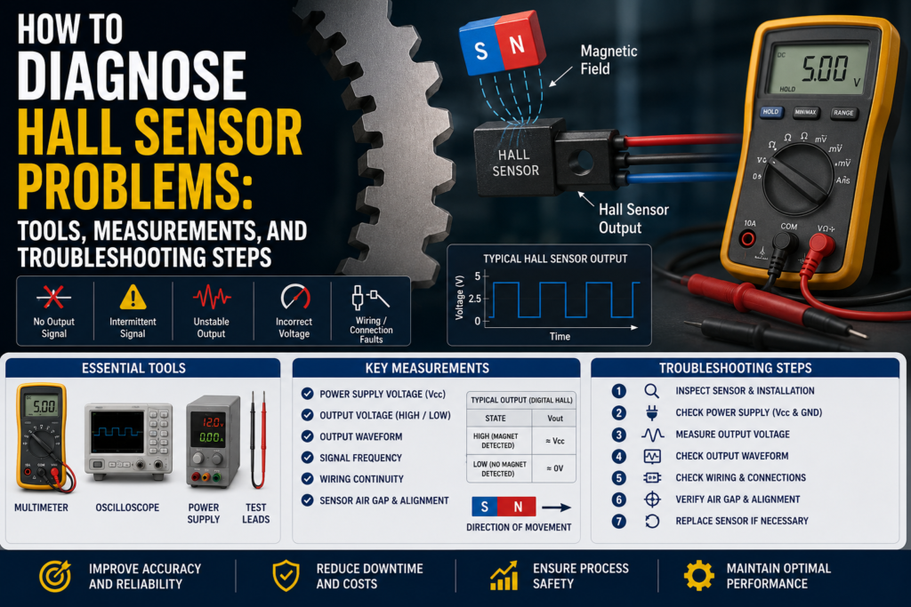
A Hall sensor detects magnetic fields and converts magnetic field changes into an electrical signal.
Hall sensors are commonly used for:
Speed measurement
Gear tooth detection
Motor feedback
Rotary position detection
Cylinder position detection
Limit detection
Magnet detection
Shaft speed monitoring
PLC pulse counting
Brushless motor commutation
Machine position feedback
When a Hall sensor does not work correctly, the problem is not always the sensor itself.
The fault can come from:
Wrong supply voltage
Wrong PNP/NPN wiring
Missing magnet
Wrong magnet polarity
Air gap too large
Weak magnet
Wrong target material
Wrong sensor type
Loose mounting bracket
Cable damage
Water inside connector
Electrical noise
PLC input too slow
Wrong high-speed counter setup
Wrong pull-up resistor
Wrong signal voltage level
Target speed too high
External magnetic interference
Wrong sensor alignment
Damaged sensor electronics
The best way to diagnose Hall sensor faults is to check the electrical signal, the magnetic target, the mechanical installation, and the PLC input step by step.
Important Safety Note
Hall sensors are often installed near moving parts.
Before troubleshooting:
Follow lockout/tagout procedures.
Keep hands away from rotating shafts, gears, belts, fans, and motors.
Do not test gear tooth sensors on exposed rotating machinery unless it is safe.
Be careful around strong magnets.
Do not short sensor output wires.
Do not apply test voltage to PLC inputs or sensor electronics unless the manual allows it.
Do not use an insulation tester on connected electronics.
If the sensor is used for speed monitoring or safety-related feedback, treat the system carefully.
First: Identify the Hall Sensor Type
Before measuring anything, identify what type of Hall sensor you have.
Common types include:
Digital Hall sensor
Analog Hall sensor
Latching Hall sensor
Unipolar Hall sensor
Bipolar Hall sensor
Gear tooth Hall sensor
Cylinder Hall sensor
Hall speed sensor
Motor Hall sensor
Hall angle sensor
Also check the output type.
Common output types include:
PNP
NPN
Push-pull
Open collector
Open drain
Analog voltage
PWM
Square wave pulse
5V logic output
24V industrial output
A 3-wire PNP Hall sensor is diagnosed differently from a 5V open collector motor Hall sensor.
Common Hall Sensor Fault Symptoms
Common symptoms include:
Sensor does not switch
Sensor always ON
Sensor always OFF
PLC input does not change
No speed reading
Speed reading jumps
Missing pulses
Extra pulses
RPM reading wrong
Motor does not start correctly
Motor runs rough
Signal disappears at high speed
Signal changes when cable is moved
Sensor works only when magnet is very close
Sensor detects sometimes but not always
Output voltage is wrong
Signal is noisy
PLC counter does not count
Sensor LED works but PLC does not see signal
Each symptom points to a different possible fault.
Tools Needed for Hall Sensor Troubleshooting
1. Digital Multimeter
A multimeter is the first tool to use.
Use it to check:
Supply voltage
PNP output voltage
NPN output behavior
Open collector pull-up voltage
Analog output voltage
Cable continuity
Short circuits
Ground problems
Connector wiring
A multimeter is enough for simple ON/OFF Hall sensor problems.
2. Oscilloscope
An oscilloscope is one of the best tools for Hall sensor troubleshooting.
Use it to check:
Square wave output
Pulse shape
Signal frequency
Signal amplitude
Missing pulses
Noise spikes
Slow edges
PWM signal
High-speed sensor output
Motor Hall sensor signals
For speed sensors, an oscilloscope is much better than a multimeter because a multimeter may not show fast pulses correctly.
3. Logic Probe or Frequency Meter
A logic probe or frequency meter can help check pulse signals.
Use it to see:
Is the output switching?
Is frequency changing with speed?
Are pulses reaching the controller?
4. PLC Software
Use PLC software to check:
Digital input state
High-speed counter value
Pulse frequency
Input filter settings
Counter configuration
Rising/falling edge setting
RPM calculation
Scaling formula
Wrong input channel
Diagnostic bits
Many Hall sensor faults are actually PLC input or counter setup problems.
5. Magnet
A small test magnet is useful for testing many Hall sensors.
Use it to check whether the sensor switches when a magnetic field is present.
But be careful:
Some Hall sensors require a specific pole.
Some latching sensors need opposite poles to reset.
Gear tooth sensors may need a ferromagnetic target, not just a magnet.
6. Feeler Gauge or Caliper
Air gap matters a lot.
Use a feeler gauge or caliper to check:
Distance between sensor and magnet
Distance between sensor and gear tooth
Target position
Sensor mounting depth
Shaft runout
Bracket movement
The correct distance depends on the sensor model and target.
Always check the datasheet.
7. Tachometer
For speed sensors, a tachometer is useful.
Use it to compare:
Real shaft speed
PLC calculated speed
Sensor pulse frequency
This helps confirm whether the RPM calculation is correct.
8. Gauss Meter / Magnetic Field Meter
A gauss meter is not always needed, but it is useful for difficult magnetic problems.
Use it to check:
Magnet strength
Magnet polarity
External magnetic interference
Magnetic field at sensor location
This is helpful when the magnet may be weak, missing, reversed, or too far away.
9. Insulation Tester
Use carefully.
An insulation tester can help find:
Damaged cable insulation
Water in connector
Short to machine frame
Moisture in junction box
Do not use it on connected Hall sensor electronics or PLC inputs.
Disconnect first and follow the manual.
Step 1: Check the Real Target or Magnet
Before blaming the sensor, check the thing it is supposed to detect.
Ask:
Is the magnet present?
Is the magnet installed in the correct direction?
Is the correct magnetic pole facing the sensor?
Is the magnet strong enough?
Is the air gap correct?
Is the target ferromagnetic?
Is the gear tooth passing close enough?
Is the sensor aimed correctly?
Is the shaft wobbling?
Is the bracket loose?
Is the target moving too fast for the input?
A Hall sensor can be electrically healthy but still not work if the magnet or target is wrong.
Step 2: Check Sensor LED or Local Status
Many industrial Hall sensors have an LED.
Check:
Power LED
Output LED
Switching LED
Fault LED
Communication LED
Good
Power LED is ON
Output LED changes when target passes
LED matches the real target position
LED switches repeatably
Bad
No power LED
Output LED never changes
Output LED always ON
LED changes but PLC input does not
LED flickers randomly
LED only works when target is very close
If the LED changes but the PLC does not, the sensor may be working and the fault may be wiring or PLC input setup.
Step 3: Check Supply Voltage
Many industrial Hall sensors use 24V DC.
Some smaller Hall sensors, motor sensors, and electronic modules use 5V DC or 12V DC.
Always check the datasheet.
Good 24V DC Supply
For many industrial sensors:
20.4V DC to 28.8V DC is usually acceptable.
This is 24V ±20%.
Good 5V DC Supply
For many 5V Hall sensors:
4.75V to 5.25V DC is usually acceptable.
Good 12V DC Supply
For many 12V sensors:
10.8V to 13.2V DC is often acceptable, but check the datasheet.
Bad Supply Readings
0V
Wrong polarity
Voltage below allowed range
Unstable voltage
Voltage drops when output switches
High ripple
Loose 0V/common wire
Sensor powered from wrong voltage
5V sensor connected to 24V
24V sensor connected to 5V
Measure the voltage directly at the sensor connector while it is connected.
Step 4: Check PNP Output
A PNP Hall sensor switches positive voltage to the PLC input.
When the sensor detects the magnet or target, the output should go high.
Good PNP Measurements
| Sensor State | Expected Output |
|---|---|
| OFF | Around 0V or floating |
| ON | Near +24V DC |
The PLC input should turn ON when the output is near +24V.
Bad PNP Measurements
Output never reaches +24V
Output stuck at +24V
Output LED ON but PLC input OFF
Wrong PLC input common
Output wire broken
Output overloaded
Output shorted to 0V
PNP sensor connected to NPN-style input
PNP/NPN mismatch is one of the most common sensor wiring problems.
Step 5: Check NPN Output
An NPN Hall sensor pulls the PLC input to 0V when active.
Good NPN Measurements
| Sensor State | Expected Output |
|---|---|
| OFF | Pulled high through input or pull-up |
| ON | Near 0V DC |
Bad NPN Measurements
Output does not pull low
Output stuck at 0V
No pull-up path
Wrong PLC input type
Wrong common wiring
Sensor output overloaded
NPN sensor wired like PNP
If the PLC input is designed only for PNP sensors, an NPN sensor may not work without changing wiring or using an interface relay/module.
Step 6: Check Open Collector or Open Drain Output
Some Hall sensors have open collector or open drain outputs.
This means the sensor does not create a full output voltage by itself.
It needs a pull-up resistor.
Good
Pull-up resistor present
Output switches between low and high
Voltage level matches controller input
Signal is clean on oscilloscope
Example:
5V pull-up system:
Output OFF = near 5V
Output ON = near 0V
24V pull-up system:
Output OFF = near 24V
Output ON = near 0V
Bad
No pull-up resistor
Output always low
Output always floating
Controller does not detect pulses
Pull-up voltage too high for sensor
Pull-up resistor too weak for high speed
Signal edges too slow
Open collector outputs are common in speed sensors and motor Hall sensors.
Step 7: Check Square Wave Pulse Output
For speed sensors, the output is often a square wave.
Use an oscilloscope.
Good Square Wave Signal
Clean ON/OFF switching
Correct voltage level
Stable frequency at constant speed
Frequency increases when speed increases
No missing pulses
No extra pulses
Fast rising and falling edges
Signal reaches PLC/controller input
Example for 24V pulse sensor:
Low level: near 0V
High level: near +24V
Example for 5V logic sensor:
Low level: near 0V
High level: near +5V
Bad Square Wave Signal
No pulses
Weak pulses
Signal stuck high
Signal stuck low
Signal amplitude too low
Noise spikes
Missing pulses
Extra pulses
Slow edges
Signal disappears at high speed
Pulse shape changes when cable moves
If the oscilloscope shows good pulses at the sensor but not at the PLC, check wiring, input type, and cable noise.
Step 8: Check Pulse Frequency and RPM
For speed measurement, the pulse frequency must match the real target speed.
Formula:
RPM = frequency × 60 / pulses per revolution
Example:
Gear has 20 teeth.
Sensor detects 20 pulses per revolution.
Measured frequency is 200 Hz.
RPM:
200 × 60 / 20 = 600 RPM
Good
Pulse frequency matches real speed
RPM calculation uses correct pulses per revolution
PLC high-speed counter counts all pulses
Speed value is stable at constant speed
Bad
Wrong pulses per revolution setting
PLC input too slow
Input filter blocks fast pulses
Counter uses wrong edge
Missing pulses at high speed
Extra pulses from noise
RPM value jumps randomly
If the sensor is used for RPM, always check both signal frequency and PLC calculation.
Step 9: Check Analog Hall Sensor Output
Analog Hall sensors output a voltage proportional to magnetic field strength or position.
Common outputs include:
0–5V
0.5–4.5V
0–10V
Ratiometric output
For many 0.5–4.5V sensors:
| Position / Field | Expected Output |
|---|---|
| Minimum | About 0.5V |
| Middle | About 2.5V |
| Maximum | About 4.5V |
For many 0–10V sensors:
| Position / Field | Expected Output |
|---|---|
| Minimum | About 0V |
| Middle | About 5V |
| Maximum | About 10V |
Good Analog Output
Voltage changes smoothly with magnet movement
Voltage stays inside expected range
No random jumps
Middle position gives middle voltage
Output matches PLC value after scaling
Bad Analog Output
0V all the time
5V all the time on a 0.5–4.5V sensor
10V all the time on a 0–10V sensor
Voltage jumps when cable is moved
Output noisy
Voltage does not change when magnet moves
Voltage outside expected range
PLC scaling set for wrong voltage range
Step 10: Check Latching Hall Sensors
A latching Hall sensor stays in one state until the opposite magnetic pole switches it back.
This is important.
A latching sensor may not turn OFF just because the magnet is removed.
It may need the opposite pole.
Good
North pole switches one state
South pole switches the opposite state
Output remains latched until opposite pole appears
Switching is repeatable
Bad
Technician expects output to turn OFF when magnet is removed
Wrong pole used
Magnet orientation incorrect
Only one pole reaches the sensor
Sensor appears stuck but is actually latched
Motor magnet ring damaged or incorrectly aligned
For latching Hall sensors, always test with both magnetic poles.
Step 11: Check Air Gap
Air gap is the distance between the Hall sensor and the magnet or target.
This is very important.
Good
Air gap is within datasheet range
Target passes consistently
No shaft wobble causing large distance changes
Sensor output switches cleanly
Signal amplitude is stable
Bad
Air gap too large
Air gap changes during rotation
Sensor only works when target is very close
Missing pulses at high speed
Output weak or unstable
Signal disappears due to vibration
Gear teeth too far from sensor
There is no universal correct air gap. It depends on the sensor, magnet, target shape, and speed.
Step 12: Check Magnet Polarity and Strength
Hall sensors may need a specific magnetic pole.
Some respond to north pole.
Some respond to south pole.
Some respond to both.
Some latch with opposite poles.
Good
Correct pole faces the sensor
Magnet is strong enough
Magnet is securely mounted
Magnet distance is correct
Magnet does not move or rotate loose
Bad
Magnet installed backwards
Magnet missing
Magnet weak
Wrong magnet type
Magnet cracked
Magnet too far away
Magnet falls out of holder
Magnet polarity does not match sensor type
Use a known working magnet or gauss meter if needed.
Step 13: Check Ferromagnetic Target
Some Hall sensors detect a ferromagnetic target passing through a magnetic field.
For example:
Gear tooth
Steel wheel
Iron target
Metal tab
Steel bolt head
Good Target
Ferromagnetic material
Correct shape
Correct size
Correct distance
Consistent movement
No wobble
Clean target surface
Bad Target
Non-magnetic stainless steel
Aluminum target
Plastic target
Target too small
Target too far away
Target wobbling
Damaged gear tooth
Target covered with thick non-magnetic material
Not every metal works well with every Hall sensor.
Aluminum and many stainless steels may not work for ferromagnetic target detection.
Step 14: Check Sensor Mounting
Mechanical mounting problems often look like electrical problems.
Check:
Loose bracket
Loose sensor nut
Wrong sensor depth
Sensor tilted
Vibration
Shaft runout
Target wobble
Magnet holder loose
Gear damage
Sensor face damaged
Good
Sensor firmly mounted
Target passes the same way every time
No bracket movement
No excessive vibration
Sensor face aligned correctly
Bad
Sensor moves when machine vibrates
Reading changes when bracket is touched
Sensor too far from target
Sensor hits target
Mounting hole loose
Gear teeth damaged
Magnet slips on shaft
If the sensor signal is not repeatable, check mechanics carefully.
Step 15: Check PLC Input Speed
For speed sensors, the PLC input must be fast enough.
A normal digital input may miss fast pulses.
High-speed counter input may be required.
Good
Input frequency rating is higher than sensor pulse frequency
Input filter is set correctly
High-speed counter is configured
Correct edge selected
PLC counts pulses consistently
Bad
Pulse frequency higher than input can handle
Input filter too slow
Normal input used instead of high-speed input
Wrong counter mode
Wrong rising/falling edge setting
PLC scan time too slow
RPM reading lower than real speed
Example:
If a gear has many teeth and rotates fast, the pulse frequency can become high quickly.
Always calculate expected frequency.
Step 16: Check Cable and Connector
Hall sensor cables often fail from vibration, oil, water, and movement.
Check:
Cable damage
Loose connector
Water inside connector
Corrosion
Broken pin
Crushed cable
Oil damage
Chemical damage
Loose terminals
Broken shield
Wrong pinout
Good
Connector dry
Cable intact
Terminals tight
No corrosion
Signal stable when cable is moved
Shield connected correctly if required
Bad
Signal changes when cable is touched
Water inside connector
Green corrosion
Intermittent signal
Broken conductor
Short to ground
Wrong pin connection
Cable pulled tight
Connector not sealed
Move the cable gently while watching the signal.
If the signal jumps, suspect cable or connector damage.
Step 17: Check Insulation Resistance
Insulation faults can cause random switching, weak signals, or no signal.
Disconnect the sensor from electronics before testing.
General Practical Values
| Insulation Resistance | Meaning |
|---|---|
| >100 MΩ | Very good |
| 20–100 MΩ | Usually acceptable, check manual |
| 1–20 MΩ | Suspicious |
| <1 MΩ | Usually bad |
Low insulation can be caused by:
Water in connector
Damaged cable
Chemical ingress
Cracked sensor housing
Condensation
Poor cable gland
Do not insulation-test connected Hall sensor electronics.
Step 18: Check Grounding and Electrical Noise
Hall sensors can be affected by electrical noise, especially pulse and analog outputs.
Common noise sources include:
VFD motor cables
Servo drives
Ignition systems
Large contactors
Solenoid valves
Welding equipment
Poor grounding
Long sensor cables
High-current conductors
Good
Sensor cable separated from power cables
Shield connected according to manual
Ground difference close to 0V
Clean square wave on oscilloscope
No false pulses when motor starts
Bad
Extra pulses when VFD starts
Speed reading jumps with motor speed
Signal has spikes
Cable routed beside motor cable
Shield disconnected
Ground difference above about 1V AC or DC
Analog output noisy
Measure voltage between sensor 0V, machine frame, and panel PE.
Ideally, it should be close to 0V.
Step 19: Check External Magnetic Interference
Because Hall sensors detect magnetic fields, nearby magnetic fields can cause problems.
Possible sources:
Permanent magnets
Magnetic brakes
Solenoids
Large motors
High DC currents
Welding cables
Magnetic clamps
Magnetized machine parts
Good
No strong external magnetic field near sensor
Sensor reacts only to intended target
Output stable when nearby devices switch
Magnet field is controlled and repeatable
Bad
Sensor switches when solenoid energizes
Sensor output changes near motor or brake
False pulses near welding equipment
Nearby magnet affects output
Machine part becomes magnetized
If the problem happens only when nearby equipment operates, check magnetic interference.
Step 20: Check Temperature Effects
Temperature can affect magnets and electronics.
Check:
Sensor temperature rating
Magnet temperature rating
Process temperature
Motor temperature
Ambient temperature
Cable temperature
Connector sealing
Good
Sensor used within temperature range
Magnet remains strong at operating temperature
Output stable after warm-up
No temperature-related drift
Bad
Sensor works cold but fails hot
Magnet weakens at high temperature
Output drifts with temperature
Connector moisture appears after thermal cycling
Cable insulation damaged by heat
Some magnets lose strength if exposed to high temperatures.
Troubleshooting by Symptom
1. Sensor Does Not Switch
Possible causes:
No power
Wrong wiring
Wrong PNP/NPN type
Magnet missing
Wrong magnetic pole
Air gap too large
Target not ferromagnetic
Sensor damaged
PLC input fault
Checks:
Measure supply voltage
Check sensor LED
Test with magnet
Measure output voltage
Check air gap
Check target material
Check PLC input
2. Sensor Always ON
Possible causes:
Magnet always near sensor
Wrong sensor type
Latching sensor not reset
External magnetic field
Output shorted
Wrong wiring
Target stuck near sensor
Checks:
Remove magnet/target
Test with opposite pole if latching
Measure output directly
Check for nearby magnets
Check cable short
Check PLC input
3. Sensor Always OFF
Possible causes:
No power
Magnet too far away
Wrong pole
Weak magnet
Wrong target material
Output wire broken
PLC input mismatch
Sensor damaged
Checks:
Measure power
Move magnet closer
Check polarity
Measure output
Check cable continuity
Check input type
4. Missing Pulses
Possible causes:
Air gap too large
Target speed too high
PLC input too slow
Input filter too slow
Weak magnet
Loose bracket
Damaged gear tooth
Signal amplitude too low
Checks:
Use oscilloscope
Check air gap
Check pulse frequency
Check high-speed counter
Inspect target
Check sensor mounting
5. Extra Pulses
Possible causes:
Electrical noise
Vibration
Target wobble
External magnetic field
Bad grounding
Damaged cable
Loose connector
Checks:
Use oscilloscope
Check cable and shield
Check grounding
Watch signal when motors start
Check bracket stability
Check magnetic interference
6. RPM Reading Wrong
Possible causes:
Wrong pulses per revolution
PLC scaling error
Missing pulses
Extra pulses
Wrong counter edge
Wrong time base
Wrong gear tooth count
Checks:
Count target teeth or magnets
Measure frequency
Use RPM formula
Compare with tachometer
Check PLC calculation
Check high-speed counter settings
7. Sensor LED Works but PLC Does Not
Possible causes:
Wrong PLC input type
Broken output wire
Wrong common
PNP/NPN mismatch
PLC input damaged
Input filter/configuration issue
Checks:
Measure output at sensor
Measure output at PLC terminal
Check input common
Check PLC input status
Test PLC input manually
Quick Measurement Table
| Test | Good Measurement | Bad Measurement |
|---|---|---|
| 24V supply | Usually 20.4–28.8V DC | Missing, low, unstable, reversed |
| 5V supply | Usually 4.75–5.25V DC | Low, high, unstable |
| PNP output ON | Near +24V DC | Low voltage or no change |
| NPN output ON | Near 0V DC | Does not pull low |
| Open collector OFF | Pull-up voltage present | Floating, no pull-up |
| Open collector ON | Near 0V DC | Does not pull low |
| 24V square wave high | Near +24V DC | Weak or noisy |
| 5V square wave high | Near +5V DC | Weak or noisy |
| Square wave low | Near 0V DC | Not pulling low |
| Analog 0.5–4.5V middle | Around 2.5V | 0V, 5V, stuck, noisy |
| Analog 0–10V middle | Around 5V | 0V, 10V, stuck, noisy |
| Insulation resistance | >100 MΩ very good | <1 MΩ usually bad |
| Ground difference | Close to 0V | >1V suspicious |
| RPM frequency | Matches target speed calculation | Missing/extra pulses |
| PLC input | Matches sensor output | Wiring or input problem |
What Measurements Are Usually Good?
These are general practical values:
24V DC sensor supply around 20.4–28.8V DC
5V sensor supply around 4.75–5.25V DC
PNP output ON close to +24V DC
NPN output ON close to 0V DC
Open collector output pulls low close to 0V DC
Square wave low level close to 0V DC
Square wave high level close to sensor logic voltage, such as 5V or 24V
Analog 0.5–4.5V sensor gives around 2.5V at middle position
Analog 0–10V sensor gives around 5V at middle position
Pulse frequency increases smoothly with speed
PLC counter matches oscilloscope frequency
Insulation resistance above 100 MΩ is very good
Ground voltage difference close to 0V
Sensor switches repeatably at the same target position
What Measurements Are Usually Bad?
These readings usually indicate a problem:
0V power supply
Wrong polarity
24V sensor supplied with only 5V
5V sensor accidentally supplied with 24V
PNP output not reaching +24V
NPN output not pulling to 0V
Open collector output with no pull-up voltage
Square wave amplitude too low
Signal stuck high
Signal stuck low
Signal noisy on oscilloscope
Missing pulses
Extra pulses
Pulse frequency does not match speed
Analog output stuck at 0V
Analog output stuck at maximum voltage
Analog output jumps when cable is touched
Insulation resistance below 1 MΩ
Ground difference above about 1V AC or DC
PLC input does not match measured sensor output
Sensor only works when magnet is extremely close
Sensor signal disappears at high speed
Practical Diagnostic Order
When diagnosing a Hall sensor, I would follow this order:
- Identify sensor type and output type.
- Check the real magnet, target, gear, or moving part.
- Check sensor LED or status indication.
- Measure supply voltage at the sensor.
- Measure output signal with a multimeter.
- For pulse sensors, check signal with an oscilloscope.
- Check PNP/NPN/open collector wiring.
- Check pull-up resistor if required.
- Check air gap and magnet polarity.
- Check target material and target shape.
- Check mechanical mounting and shaft wobble.
- Check PLC input or high-speed counter configuration.
- Compare RPM with a tachometer if speed is measured.
- Check cable, connector, and terminals.
- Check insulation resistance if allowed.
- Check grounding, shielding, and electrical noise.
- Check external magnetic interference.
- Check temperature effects if the fault appears only hot or cold.
This order helps avoid replacing a good Hall sensor when the real problem is wiring, air gap, magnet polarity, target material, or PLC counter setup.
Final Thoughts
Hall sensor troubleshooting is both an electrical and mechanical task.
A Hall sensor may be electrically healthy but still fail if the magnet is missing, the wrong pole faces the sensor, the air gap is too large, the target is not ferromagnetic, or the PLC input cannot count the pulses fast enough.
The most useful tools are:
Digital multimeter
Oscilloscope
Logic probe
PLC software
Test magnet
Feeler gauge or caliper
Tachometer
Gauss meter
Insulation tester
The most important checks are:
Supply voltage
PNP/NPN output voltage
Open collector pull-up
Square wave signal
Pulse frequency
Analog voltage output
Air gap
Magnet polarity
Target material
PLC input status
High-speed counter setup
Cable and connector condition
Grounding and noise
The key rule is simple:
If the sensor LED changes but the PLC does not, check wiring and PLC input type.
If the sensor output is clean but speed is wrong, check pulse count and PLC scaling.
If the sensor does not switch at all, check power, magnet polarity, air gap, and target material.