
A Hall sensor is a sensor that detects magnetic fields.
In industrial automation, Hall sensors are often used to detect the presence, position, speed, or movement of a ferromagnetic object or magnet.
They are commonly used in:
Speed sensors
Position sensors
Gear tooth detection
Rotary speed measurement
Motor feedback
Cylinder position detection
Limit detection
Machine monitoring
Automotive sensors
Conveyor systems
PLC input signals
Non-contact switching applications
The basic idea is simple:
A Hall sensor detects a change in magnetic field and converts it into an electrical signal.
This makes Hall sensors useful when you want to detect movement or position without direct mechanical contact.
What Is a Hall Sensor?
A Hall sensor is an electronic sensor that uses the Hall effect to detect magnetic fields.
Inside the sensor is a small semiconductor element.
This semiconductor element carries an electrical current.
When a magnetic field acts on the semiconductor, it creates a small voltage change.
The electronics inside the sensor detect this voltage and convert it into a usable output signal.
In simple words:
Magnetic field changes → Hall element voltage changes → electronics create sensor output.
What Is the Hall Effect?
The Hall effect is a physical effect that happens when current flows through a conductor or semiconductor and a magnetic field passes through it.
The moving electrical charges are pushed to one side by the magnetic field.
This creates a small voltage across the material.
This voltage is called the Hall voltage.
The stronger the magnetic field, the larger the Hall voltage.
So the Hall sensor can use this voltage to detect magnetic field strength or magnetic field changes.
Simple Hall Effect Explanation
Imagine current flowing through a small semiconductor plate.
A magnetic field crosses the plate.
The magnetic field pushes the moving charges slightly to one side.
This creates a small voltage difference.
The sensor electronics measure this voltage difference.
That voltage tells the sensor that a magnetic field is present.
Basic Working Principle of a Hall Sensor
A Hall sensor usually contains:
Current-carrying semiconductor element
Magnet or magnetic field source
Signal processing electronics
Amplifier
Output stage
Housing
Electrical connector or cable
The semiconductor element is the part that reacts to the magnetic field.
The electronics amplify and process the small Hall voltage.
The output stage sends a usable signal to a PLC, controller, drive, or monitoring device.
Hall Sensor With Permanent Magnetic Bias
Many industrial Hall sensors include or use a permanent magnet.
This magnet creates a magnetic field around the sensor.
This is sometimes called magnetic bias or magnetic pre-magnetization.
When no target is near the sensor, the magnetic field has a normal condition.
When a ferromagnetic object enters the magnetic field, the field changes.
The Hall element detects this magnetic field change.
The electronics convert it into an output signal.
What Is a Ferromagnetic Object?
A ferromagnetic object is a material that strongly interacts with magnetic fields.
Common ferromagnetic materials include:
Steel
Iron
Nickel
Cobalt
Many machine shafts
Gear teeth
Metal targets
Steel bolts
Steel plates
When one of these objects enters the magnetic field near the Hall sensor, it changes the magnetic field shape and intensity.
The Hall sensor detects this change.
Step-by-Step Working Principle
A simple Hall sensor detection process works like this:
A current flows through the Hall semiconductor element.
A permanent magnet creates a magnetic field.
The Hall element is exposed to this magnetic field.
A ferromagnetic target enters or leaves the field.
The magnetic field intensity changes.
The Hall voltage changes.
The internal electronics amplify the signal.
The electronics convert it into a switching or pulse output.
The PLC or controller reads the output.
So the sensor does not need to physically touch the target.
It detects the magnetic field change caused by the target.
How the Hall Voltage Becomes a Sensor Signal
The raw Hall voltage is very small.
It is not usually sent directly to the PLC.
The sensor electronics process the signal.
This usually includes:
Signal amplification
Filtering
Threshold detection
Signal shaping
Temperature compensation
Output switching
In many Hall sensors, the internal electronics convert the changing Hall voltage into a clean square wave signal.
This is useful because PLCs and controllers can read square wave pulses more easily than small analog sine-like signals.
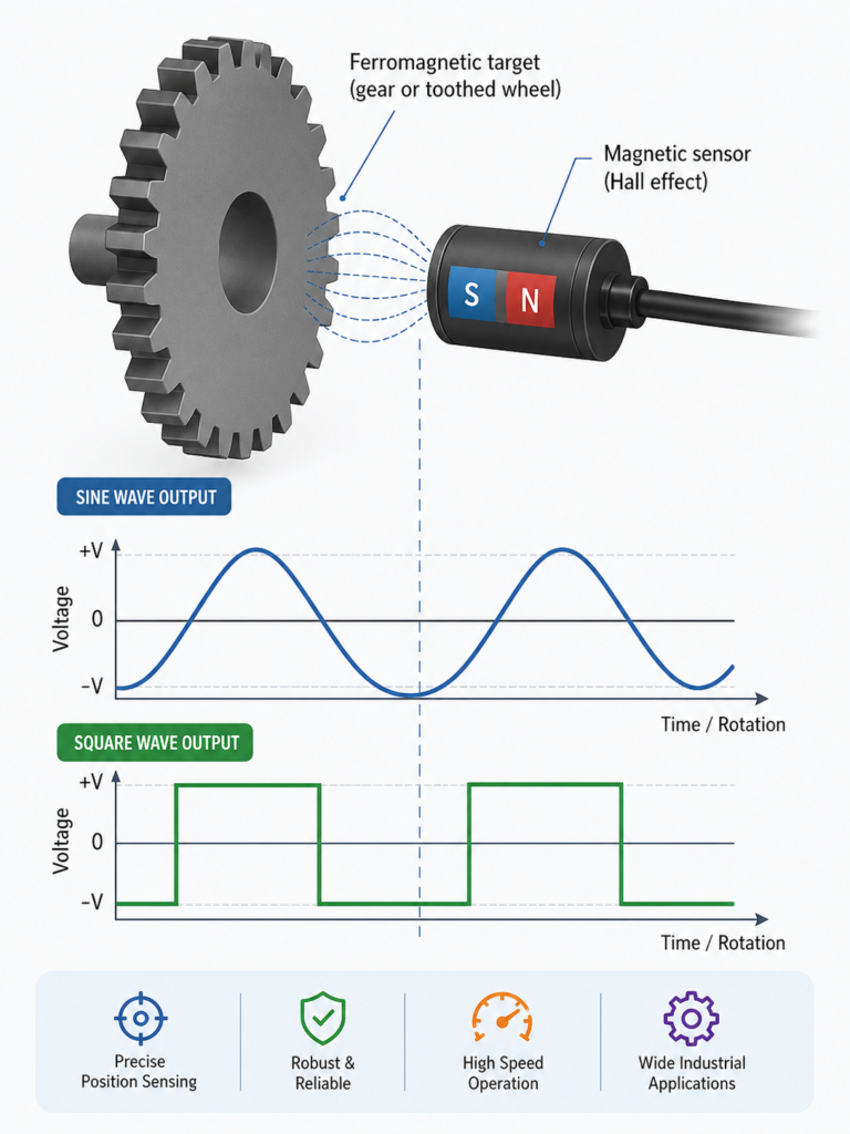
Sine Signal to Square Wave Signal
When a moving ferromagnetic target passes the sensor, the magnetic field changes gradually.
This can create a smooth changing voltage signal inside the sensor.
Depending on the movement, the raw signal may look like a sine wave or a smooth analog waveform.
The internal electronics evaluate this signal and convert it into a clean digital output.
The output may look like a square wave.
This square wave can be used for:
Speed measurement
Counting pulses
Position detection
Frequency measurement
Gear tooth detection
Motor speed feedback
Example: Gear Tooth Detection
A Hall sensor can be mounted near a rotating steel gear.
The sensor has a magnetic field.
As each tooth passes the sensor, it changes the magnetic field.
The sensor electronics detect each change and create one pulse.
The controller counts the pulses.
From the pulse frequency, the controller can calculate speed.
For example:
Slow gear rotation = low pulse frequency
Fast gear rotation = high pulse frequency
This is one of the most common uses of Hall sensors.
Digital Hall Sensors
A digital Hall sensor gives an ON/OFF output.
It switches when the magnetic field reaches a certain threshold.
Typical digital outputs include:
PNP
NPN
Push-pull
Open collector
Open drain
Square wave pulse output
Digital Hall sensors are used when you only need to know whether a target or magnet is present.
They are also used for pulse counting and speed measurement.
Digital Hall Sensor Example
A magnet is mounted on a rotating wheel.
The Hall sensor is fixed nearby.
Each time the magnet passes the sensor, the output switches ON.
The PLC counts the pulses.
If the wheel rotates faster, the pulses come faster.
This can be used to measure speed or detect rotation.
Analog Hall Sensors
An analog Hall sensor gives an output proportional to magnetic field strength.
Instead of only switching ON or OFF, it provides a changing voltage.
Common analog outputs include:
0–5V
0.5–4.5V
0–10V
Ratiometric voltage output
Analog Hall sensors are used for:
Position measurement
Angle sensing
Current sensing
Magnetic field measurement
Small displacement measurement
For example, if a magnet moves closer to the sensor, the output voltage may increase.
If the magnet moves away, the output voltage may decrease.
Latching Hall Sensors
A latching Hall sensor changes state when it sees one magnetic pole and stays in that state until it sees the opposite pole.
For example:
North pole switches output ON.
South pole switches output OFF.
This is useful in rotating systems where alternating magnetic poles pass the sensor.
Latching Hall sensors are common in:
Brushless DC motors
Speed sensing
Rotary position detection
Commutation feedback
Unipolar and Bipolar Hall Sensors
Hall sensors can also be described as unipolar or bipolar.
Unipolar Hall Sensor
A unipolar sensor responds to one magnetic pole.
For example, it may switch ON when a south pole is near and switch OFF when the field is removed.
Bipolar Hall Sensor
A bipolar sensor responds to both magnetic polarities.
It may switch ON with one pole and OFF with the opposite pole.
The correct type depends on the magnet arrangement and application.
Hall Sensor Output Signals
Hall sensors can provide different output signals.
Common outputs include:
PNP switching output
NPN switching output
Push-pull output
Open collector output
Open drain output
Square wave pulse output
Analog voltage output
PWM output
Digital communication output
In PLC systems, PNP and NPN outputs are common.
In speed measurement, square wave pulse outputs are common.
In position measurement, analog voltage outputs are common.
PNP Hall Sensor Output
A PNP Hall sensor switches positive voltage to the PLC input.
When the sensor detects the target, the output wire goes high.
Typical example:
Output OFF = 0V or floating
Output ON = +24V DC
PNP sensors are very common in European industrial automation.
NPN Hall Sensor Output
An NPN Hall sensor switches the output to 0V.
When the sensor detects the target, the output is pulled low.
Typical example:
Output OFF = pulled high through input circuit
Output ON = near 0V DC
NPN sensors are also common, but the PLC input must be wired correctly.
A PNP/NPN mismatch is a common wiring mistake.
Square Wave Output
A Hall sensor used for speed detection often creates a square wave output.
Each pulse represents a target passing the sensor.
The controller can use this for:
Counting
Speed measurement
RPM calculation
Position indexing
Movement detection
For example, if a gear has 20 teeth and the sensor detects 20 pulses per revolution, the PLC can calculate RPM from pulse frequency.
Hall Sensors for Speed Measurement
Hall sensors are commonly used to measure rotational speed.
They can detect:
Gear teeth
Magnets on rotating shafts
Slots in a wheel
Ferromagnetic targets
Magnetic encoder rings
The sensor creates pulses as the target rotates.
The PLC or controller measures the pulse frequency.
Higher frequency means higher speed.
Simple RPM Example
Suppose a wheel has one magnet.
The Hall sensor detects one pulse per revolution.
If the controller reads 10 pulses per second, then:
10 revolutions per second × 60 = 600 RPM
If the wheel has 10 magnets and the controller reads 100 pulses per second:
100 pulses per second ÷ 10 magnets = 10 revolutions per second
10 × 60 = 600 RPM
Hall Sensors for Position Detection
Hall sensors can also detect position.
Examples:
Door open/closed
Cylinder position
End position of a mechanism
Rotary index position
Valve position confirmation
Home position detection
Motor rotor position
For simple position detection, a magnet may be mounted on the moving part.
When the magnet reaches the sensor, the output switches.
Hall Sensors in Motors
Hall sensors are commonly used inside brushless DC motors.
They detect rotor position.
The motor controller uses this information to switch current to the correct motor windings.
This is called commutation feedback.
Without position feedback, the controller may not know the rotor position at startup.
Hall sensors help the controller run the motor smoothly.
Hall Sensor vs Inductive Sensor
Hall sensors and inductive sensors can both detect metal or position, but they work differently.
Hall Sensor
Detects magnetic field changes
Often needs a magnet or magnetic bias
Can detect magnets directly
Can detect ferromagnetic targets with a magnet
Useful for speed and rotation
Can work with magnetic encoder rings
Inductive Sensor
Creates an electromagnetic field
Detects conductive metal targets
Does not need a magnet
Common for simple metal detection
Good for proximity detection
Use a Hall sensor when magnetic detection or speed pulses are needed.
Use an inductive sensor when you want simple metal presence detection without magnets.
Hall Sensor vs Reed Switch
A reed switch also detects magnetic fields.
It uses mechanical contacts sealed inside a glass tube.
A Hall sensor is fully electronic.
Reed Switch Advantages
Simple
No power needed for basic contact
Easy to understand
Can switch small loads directly
Reed Switch Limitations
Mechanical contacts
Contact wear
Contact bounce
Slower switching
Less suitable for high-frequency speed detection
Hall Sensor Advantages
No mechanical contacts
Fast switching
Long service life
Good for high-speed pulses
Can provide analog or digital output
Better for electronic control systems
For high-speed or long-life applications, Hall sensors are usually better than reed switches.
Advantages of Hall Sensors
Hall sensors have many advantages:
Non-contact detection
No mechanical wear
Fast switching
Good for speed measurement
Good for rotary position detection
Can detect magnets directly
Can detect ferromagnetic targets with magnetic bias
Works in dirty or oily environments
Can provide square wave output
Can be compact
Can be used in motors and automation systems
Limitations of Hall Sensors
Hall sensors also have limitations:
Sensitive to magnetic field strength
Magnet alignment matters
Air gap matters
External magnetic fields can cause errors
Ferromagnetic target shape affects signal
Sensor must be selected for the correct magnetic polarity
Temperature can affect magnetic strength and electronics
Wrong wiring can damage the sensor
Not every metal can be detected unless the system is designed for it
Hall sensors are reliable, but the magnet, target, air gap, and mounting are very important.
Installation Tips for Hall Sensors
Good installation is important for stable detection.
Check:
Correct air gap
Correct magnet orientation
Correct target material
Stable sensor mounting
Stable target movement
No excessive shaft wobble
Correct cable routing
No strong magnetic interference nearby
Correct supply voltage
Correct PNP/NPN wiring
Correct PLC input type
Proper shielding if needed
Good Installation
Sensor firmly mounted
Magnet or target passes repeatably
Air gap is within datasheet limits
Cable is protected
No strong external magnets nearby
Output changes clearly
PLC input matches output type
Bad Installation
Air gap too large
Magnet too weak
Wrong magnet pole facing sensor
Target not ferromagnetic
Sensor bracket loose
Target wobbles
Cable routed near high-power motor cables
Wrong PNP/NPN input wiring
External magnetic field interfering
A Hall sensor can be electrically healthy but still fail if the magnet or target setup is wrong.
How Hall Sensors Connect to a PLC
A simple PLC connection looks like this:
Hall sensor receives power, often 24V DC.
Sensor detects magnet or ferromagnetic target.
Sensor output switches ON/OFF or sends pulses.
PLC digital input reads the signal.
PLC logic uses the signal for control, counting, or speed measurement.
For speed measurement, the PLC may use a high-speed counter input.
For simple position detection, a normal digital input may be enough.
Example: Hall Sensor for Gear Speed
A Hall sensor is mounted near a steel gear.
The sensor has a magnetic field.
As each gear tooth passes, the field changes.
The Hall sensor creates a pulse.
The PLC counts the pulses using a high-speed counter.
The PLC calculates RPM.
This setup can be used for:
Conveyor speed
Motor shaft speed
Machine cycle monitoring
Rotary feeder speed
Pump speed feedback
Example: Hall Sensor for Cylinder Position
A magnet is built into or attached to a moving part.
The Hall sensor is fixed along the travel path.
When the magnet reaches the sensor, the output switches.
The PLC detects that the part has reached the correct position.
This can be used for:
Pneumatic cylinders
Linear slides
Door position
Machine end stops
Home position detection
Choosing a Hall Sensor
Before choosing a Hall sensor, check:
Do you need digital or analog output?
Do you detect a magnet or ferromagnetic target?
What is the required sensing distance?
What is the air gap?
What is the target speed?
What is the required switching frequency?
Do you need PNP or NPN output?
What supply voltage is available?
Does the PLC need a high-speed input?
Is the environment wet, oily, dusty, or hot?
Are there strong magnetic fields nearby?
Is the target shape suitable?
Is the magnet polarity correct?
Is the cable length acceptable?
The correct Hall sensor depends on the magnet, target, speed, output, and environment.
Common Hall Sensor Problems
Common problems include:
Sensor does not switch
Sensor always ON
Sensor always OFF
Missing pulses
Extra pulses
Unstable speed reading
PLC does not count pulses
Output signal weak
Wrong PNP/NPN wiring
Magnet installed backwards
Air gap too large
External magnetic interference
Loose sensor bracket
Wrong target material
Cable damage
Electrical noise
Target speed too high for PLC input
Many of these are installation or wiring problems, not sensor failure.
Final Thoughts
Hall sensors detect magnetic fields using the Hall effect.
Inside the sensor is a current-carrying semiconductor element.
When a magnetic field acts on this element, a small Hall voltage is generated.
If a magnet moves, or if a ferromagnetic object enters the magnetic field, the magnetic field changes.
The sensor electronics detect this voltage change, amplify it, and convert it into a usable output.
In many industrial sensors, the raw changing signal is converted into a clean square wave output.
This makes Hall sensors very useful for speed measurement, gear tooth detection, position detection, motor feedback, and non-contact switching.
The key idea is:
A Hall sensor detects magnetic field changes and converts them into an electrical signal that a PLC or controller can use.