A rotating magnetic field is interesting, but on its own it does not drive a conveyor, spin a pump or turn a cooling fan.
The rotor still has to respond.
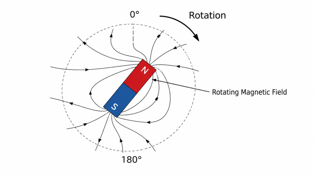
This is where an AC motor begins to feel almost a little mysterious. The stator windings remain completely stationary, there may be no electrical connection to the rotor at all, and yet the rotor begins accelerating as soon as power is applied.
No hidden gears. No tiny electrical motor inside the bigger motor. Just magnetic fields interacting across a small air gap.
To understand how that happens, it helps to begin with the easiest rotor imaginable: a permanent magnet mounted on a shaft.
Imagine a Permanent Magnet Inside the Stator
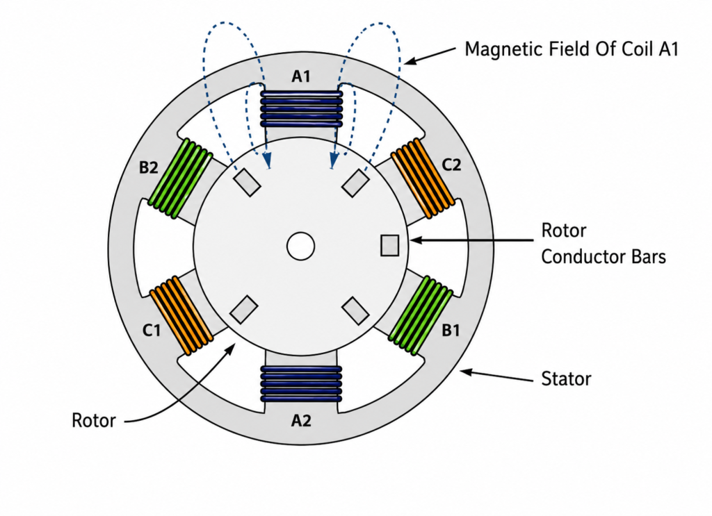
Suppose we temporarily replace the squirrel-cage rotor with a simple bar magnet that is free to rotate.
The magnet has a north pole at one end and a south pole at the other. When the three-phase stator windings are energized, they create the rotating magnetic field discussed in the previous article.
Now two magnetic fields exist inside the motor:
- The rotating field produced by the stator
- The fixed magnetic field of the permanent-magnet rotor
Opposite magnetic poles attract each other.
The north pole of the stator field attracts the south pole of the rotor magnet. At the same time, the stator’s south pole attracts the rotor’s north pole.
Because the stator field is continuously rotating, the rotor magnet is continuously pulled toward a new position. It follows the moving field around the stator.
The shaft turns with it.
This is the basic operating idea behind a permanent-magnet synchronous motor, often shortened to PMSM.
Once operating normally, the permanent-magnet rotor remains locked to the rotating stator field. If the stator field completes 1,500 revolutions per minute, the rotor also completes 1,500 revolutions per minute.
There is no continuous speed difference between them.
That is why it is called a synchronous motor.
A squirrel-cage induction motor is different. It does not normally contain permanent magnets, and its rotor is not supplied directly from an external electrical source.
Its magnetic field must be created indirectly.
That is where induction enters the story.
What Is Inside a Squirrel-Cage Rotor?
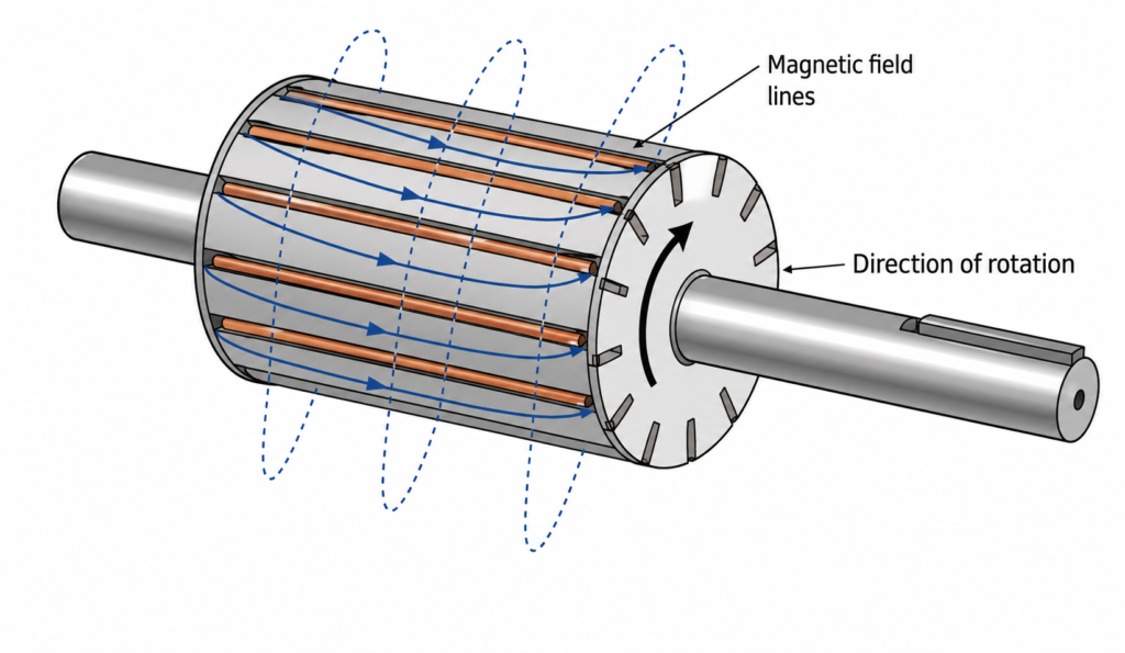
A squirrel-cage rotor is built from conductive bars installed lengthwise through a laminated steel rotor core.
These bars are joined together at both ends by conductive end rings. The arrangement resembles a circular cage, which is how the design acquired its slightly odd name.
The rotor bars are commonly made from aluminium or copper. Since the bars are connected by the end rings, they form closed electrical circuits.
There are usually no brushes.
No commutator.
No cable running into the spinning rotor.
The stator transfers energy to the rotor through electromagnetic induction, across the narrow air gap between them.
That simple construction is one reason squirrel-cage motors are so widely used. There is not much inside the rotor to wear out, at least compared with motors that rely on brushes, commutators or mechanical switching contacts.
The Stator Field Cuts Across the Rotor Bars
When three-phase power is applied to the stator, current begins flowing through the stator windings.
The windings create a rotating magnetic field. At the moment of startup, the rotor is stationary while this magnetic field sweeps around it at synchronous speed.
Consider a four-pole motor connected to a 50 Hz supply.
Its rotating magnetic field travels at:
Ns = 120 × f ÷ P
Ns = 120 × 50 ÷ 4
Ns = 1,500 RPM
The rotor, however, begins at zero RPM.
That means the stator field is moving rapidly relative to the rotor conductors. As its magnetic flux crosses the rotor bars, a voltage is induced in them.
This follows the same basic principle used by transformers and generators: when a conductor experiences a changing magnetic field, an electromotive force is produced.
The induced voltage is often called:
- Induced EMF
- Rotor EMF
- Induced voltage
Because the rotor bars are connected through the end rings, the induced voltage causes current to circulate through the rotor cage.
And current flowing through a conductor creates a magnetic field.
The once-passive rotor has now become an electromagnet.
The Rotor Does Not Need a Direct Power Connection
This is one of the most useful things to understand about an induction motor.
The stator is connected to the electrical supply. The squirrel-cage rotor usually is not.
Instead, the rotor receives electrical energy through induction.
The process happens in stages:
- Current flows through the stator windings.
- The stator creates a rotating magnetic field.
- The moving field cuts across the rotor conductors.
- Voltage is induced in the rotor bars.
- Current flows through the bars and end rings.
- Rotor current produces a rotor magnetic field.
- The stator and rotor fields interact.
- Electromagnetic torque turns the rotor.
It sounds like quite a chain when written out, yet all of it begins almost instantly after the motor is energized.
This is also why an induction motor can draw a large current during startup. Initially, the speed difference between the stator field and rotor is at its greatest. Strong rotor currents are induced, and the stator must supply the energy needed to establish them while accelerating the mechanical load.
How the Rotor Magnetic Field Produces Torque
The induced rotor current creates magnetic poles in the rotor.
These rotor poles interact with the rotating magnetic field produced by the stator. The interaction creates a tangential force around the rotor circumference, producing torque on the shaft.
A simplified explanation is that opposite magnetic poles attract while like poles repel.
That is useful for visualizing what happens, although the real distribution of magnetic flux inside an induction motor is more complex than a few perfectly defined north and south poles.
The important part is this: the rotor field develops in a direction that opposes the relative movement responsible for inducing it.
That behaviour follows Lenz’s law.
The rotor does not oppose rotation in the sense of trying to stop the motor. Instead, it attempts to reduce the relative speed between itself and the rotating stator field.
The easiest way to do that is to accelerate in the same direction as the field.
So the rotor begins to turn.
As the stator field moves forward, the induced rotor field follows behind it. Torque continues to act, and the rotor speeds up.
Why the Rotor Cannot Catch the Magnetic Field
At first glance, it may seem that the rotor should eventually catch up and rotate at exactly the same speed as the stator field.
But a normal induction motor cannot do that while producing torque.
Imagine that the rotor reaches synchronous speed.
The stator field and rotor would now rotate together at exactly the same speed. There would be no relative movement between the rotating field and the rotor bars.
If no magnetic flux moves relative to the rotor bars:
- No rotor voltage is induced
- Rotor current falls
- The rotor magnetic field weakens
- Electromagnetic torque falls
The rotor would then slow slightly under the mechanical load.
As soon as it slows below synchronous speed, relative movement returns. Voltage is induced again, rotor current increases and torque is restored.
The motor therefore settles at a speed slightly below synchronous speed.
That small speed difference is called slip.
Without slip, there is no continuous induction.
Without induction, there is no useful rotor current.
And without rotor current, an induction motor cannot produce steady torque.
Slip is not a design failure. It is essential to the motor’s operation.
What Is Motor Slip?
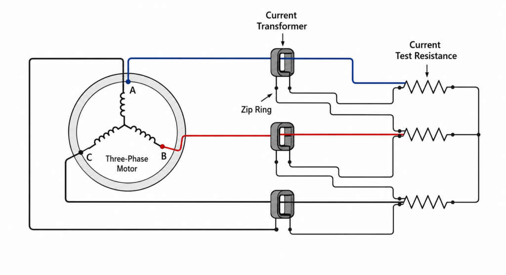
Slip is the difference between the synchronous speed of the rotating magnetic field and the actual mechanical speed of the rotor.
It is normally expressed as a percentage.
The formula is:
Slip (%) = ((Ns − Nr) ÷ Ns) × 100
Where:
- Ns = synchronous speed in RPM
- Nr = actual rotor speed in RPM
Suppose a four-pole motor operates from a 60 Hz supply.
Its synchronous speed is:
Ns = 120 × 60 ÷ 4
Ns = 1,800 RPM
If the rotor turns at 1,765 RPM under full load:
Slip = ((1,800 − 1,765) ÷ 1,800) × 100
Slip = (35 ÷ 1,800) × 100
Slip ≈ 1.94%
Rounded off, the motor has approximately 1.9% slip.
The magnetic field is rotating at 1,800 RPM, while the shaft is turning at 1,765 RPM.
Only 35 RPM separates them, but that difference is enough to maintain rotor induction and produce the torque required by the load.
Slip Changes With Mechanical Load
Slip is not always fixed at one exact value.
Imagine an induction motor driving a lightly loaded fan. The motor only needs a modest amount of torque, so the rotor can run quite close to synchronous speed.
Now increase the mechanical load.
Perhaps a conveyor becomes heavily loaded, a pump encounters greater pressure or a machine begins cutting material.
The rotor slows slightly.
As rotor speed decreases, slip increases. The rotating stator field cuts across the rotor bars more rapidly, inducing greater rotor voltage and current.
More rotor current generally produces a stronger rotor magnetic field and additional torque.
The motor responds to the increased load automatically.
The sequence looks like this:
- Mechanical load increases
- Rotor slows slightly
- Slip increases
- More rotor EMF is induced
- Rotor current increases
- Motor torque increases
When the mechanical load decreases, the opposite happens:
- Rotor accelerates
- Slip decreases
- Induced rotor voltage decreases
- Rotor current falls
- Developed torque decreases
The rotor continuously settles at the speed where motor torque matches the mechanical torque demanded by the load.
It is a self-balancing process, although only within the motor’s designed operating limits.
What Happens If the Load Is Too High?
A motor cannot increase slip forever and continue operating normally.
If the load rises beyond the motor’s available torque, the rotor slows substantially. Current rises, heating increases and the motor may eventually stall.
A stalled induction motor has:
- Zero rotor speed
- Maximum slip
- High current
- Little or no useful mechanical output
- Rapid temperature rise
At standstill, slip is 100% because the rotor is not moving while the stator field continues rotating at synchronous speed.
This condition should not be allowed to continue. Motor overload protection is intended to disconnect the supply before excessive heating damages the windings.
A jammed conveyor or seized bearing can turn a perfectly healthy motor into a heater surprisingly quickly.
Slip at Different Operating Conditions
The approximate slip of an induction motor depends on its design, size and load.
Typical conditions look like this:
| Motor condition | Approximate slip |
|---|---|
| Rotor stopped | 100% |
| Motor starting | Close to 100% |
| Running with very light load | Very low |
| Running at rated load | Often around 1–5% |
| Severely overloaded | Higher than normal |
| Synchronous speed | 0%, but no induction torque |
Large, efficient motors often operate with relatively low full-load slip. Smaller motors may have somewhat higher slip.
The motor nameplate speed gives a useful clue.
A four-pole motor on a 50 Hz system has a synchronous speed of 1,500 RPM. If its nameplate states 1,460 RPM, the rated slip is:
Slip = ((1,500 − 1,460) ÷ 1,500) × 100
Slip ≈ 2.67%
That is entirely normal.
The motor is not “losing” 40 RPM because something is wrong. It needs that speed difference to develop torque.
Rotor Frequency Also Changes With Slip
Another useful detail is that the electrical frequency induced in the rotor depends on slip.
At startup, the rotor is stationary. The rotating field passes the rotor conductors at the full supply frequency.
Therefore, when a 50 Hz induction motor is first energized, the rotor current frequency is initially 50 Hz.
As the rotor accelerates, the relative speed decreases. Rotor frequency falls.
The relationship is:
Rotor frequency = Slip × Supply frequency
Slip must be written as a decimal in this equation.
For example, if a 50 Hz motor operates with 2% slip:
Rotor frequency = 0.02 × 50
Rotor frequency = 1 Hz
The stator is supplied at 50 Hz, but the rotor current may only alternate at around 1 Hz while the motor runs near rated speed.
That surprises plenty of people the first time they encounter it.
Permanent-Magnet Synchronous Motors
A permanent-magnet synchronous motor uses magnets in or on the rotor instead of relying solely on induced rotor current.
The stator still creates a rotating magnetic field. The permanent magnets produce a rotor field that attempts to align with it.
During normal operation, the rotor remains locked in step with the rotating field.
Therefore:
Rotor speed = Synchronous speed
There is no normal induction-motor slip between the rotor and stator field.
These motors can offer:
- High efficiency
- High power density
- Good torque control
- Reduced rotor losses
- Accurate speed regulation
They are widely used in servo systems, electric vehicles, robotics, compressors, pumps and modern variable-speed industrial machinery.
However, most permanent-magnet synchronous motors require an electronic drive to start and control them properly. The drive controls stator frequency, phase and current so that the rotating magnetic field remains correctly positioned relative to the rotor magnets.
Without suitable control, the rotor may fail to synchronize or produce unstable torque.
Electrically Excited Synchronous Motors
Not every synchronous motor uses permanent magnets.
In an electrically excited synchronous motor, the rotor contains DC field windings. Direct current produces a constant magnetic field with defined north and south poles.
Traditionally, DC may be supplied to the rotor through slip rings and brushes. Some machines instead use brushless excitation systems.
The stator receives three-phase AC and develops a rotating magnetic field. Once the rotor is brought close to synchronous speed, its DC magnetic field locks onto the rotating stator field.
The rotor then turns at exactly synchronous speed.
For example, a four-pole synchronous motor connected to a 50 Hz supply runs at 1,500 RPM, assuming it remains synchronized.
Unlike an induction motor, it does not normally settle at 1,460 or 1,480 RPM.
It runs at 1,500 RPM.
If the load becomes too large, however, the rotor may lose synchronism rather than simply operating with steadily increasing slip. This condition is sometimes described as pulling out of step.
How a Traditional Synchronous Motor Starts
A synchronous motor cannot always produce useful self-starting torque from its DC rotor field alone.
The rotating stator field moves too quickly for a stationary rotor to lock onto it immediately. The rotor may simply experience alternating forces rather than smooth acceleration.
To solve this, some synchronous motors include damper bars in the rotor. These resemble the bars of a squirrel-cage rotor.
During startup:
- Three-phase AC is applied to the stator.
- The damper bars behave like a squirrel-cage rotor.
- Induction torque accelerates the motor.
- The rotor approaches synchronous speed.
- DC excitation establishes a strong rotor magnetic field.
- The rotor locks into step with the stator field.
Once synchronized, the motor runs at synchronous speed.
Modern drive-controlled synchronous motors can use a different starting method. The drive begins at a low output frequency and gradually increases it, allowing the rotor to follow the magnetic field from standstill.
The Wound-Rotor Induction Motor
The squirrel-cage motor is the most common induction motor, but it is not the only design.
A wound-rotor motor uses insulated windings in the rotor instead of permanently short-circuited bars.
The rotor windings are usually connected to slip rings mounted on the shaft. Stationary brushes make electrical contact with the rings, allowing external resistors or control equipment to be connected to the rotor circuit.
The stator still produces a rotating magnetic field.
The field still induces voltage and current in the rotor.
So despite its different construction, a wound-rotor motor remains an induction motor.
Why Add External Rotor Resistance?
Adding resistance to the rotor circuit changes the motor’s starting characteristics.
Properly selected external resistance can:
- Increase starting torque
- Limit starting current
- Provide smoother acceleration
- Assist with starting heavy loads
- Allow limited speed control
This made wound-rotor motors useful for cranes, hoists, mills, crushers and other machines that had to start under substantial mechanical load.
As the motor accelerates, the external resistance is normally reduced in stages. Once the motor reaches normal operating speed, the rotor windings may be effectively short-circuited.
There is an important nuance here.
Increasing rotor resistance does not simply make the motor “weaker” in every situation. It changes where maximum torque occurs on the motor’s torque-speed curve. Additional resistance can actually improve starting torque, even though it also increases losses and causes the motor to operate with greater slip when used for speed reduction.
Using rotor resistance for continuous speed control wastes energy as heat. For that reason, modern VFD-controlled squirrel-cage motors have replaced wound-rotor speed control in many applications.
Wound-rotor motors still exist, though, especially in older industrial installations and certain heavy-duty duties.
Squirrel-Cage, Wound-Rotor and Synchronous Motors Compared
| Feature | Squirrel-cage induction motor | Wound-rotor induction motor | Synchronous motor |
| Rotor construction | Conductive bars and end rings | Three-phase rotor windings | Permanent magnets or DC field winding |
| Rotor electrical connection | Normally none | Slip rings and brushes | May use magnets, slip rings or brushless excitation |
| Operating speed | Below synchronous speed | Below synchronous speed | At synchronous speed |
| Slip required for torque | Yes | Yes | No continuous induction slip |
| Starting behaviour | Usually self-starting | Self-starting with controllable rotor resistance | May require damper bars or an electronic drive |
| Maintenance | Relatively low | Higher due to brushes and rings | Depends on rotor and excitation design |
| Common use | Pumps, fans, conveyors, machinery | Hoists, cranes and heavy-starting loads | Precision-speed and high-efficiency applications |
Each design relies on the stator’s rotating magnetic field, but the rotor responds in a different way.
What Determines the Direction of Rotor Rotation?
The rotor follows the direction of the rotating stator field.
In a three-phase motor, field direction is determined by phase sequence.
For example:
- A-B-C sequence creates rotation in one direction
- A-C-B sequence creates rotation in the opposite direction
Swapping any two incoming phases reverses the phase sequence.
The rotating magnetic field reverses, and the rotor accelerates in the opposite direction.
This applies to most standard three-phase induction motors. It also applies to many synchronous motor systems, although drive-controlled motors may reverse through software or control commands rather than by manually swapping supply conductors.
Always confirm that the driven machine can safely rotate in the opposite direction before performing a phase swap. Some pumps, compressors and mechanical systems can be damaged by reverse operation.
Common Rotor-Related Motor Problems
Understanding rotor operation helps explain several faults encountered in real installations.
Broken rotor bars
Cracked or broken bars disturb rotor current distribution.
Possible symptoms include:
- Reduced starting torque
- Vibration
- Pulsating torque
- Unusual noise
- Increased current
- Heating
- Performance that worsens under load
Broken bars may be difficult to identify without motor current analysis, vibration testing or specialized inspection.
Damaged end rings
The end rings complete the squirrel-cage circuit. Cracks or poor connections interfere with rotor current flow and may produce symptoms similar to broken bars.
Excessive slip
Higher-than-normal slip may indicate:
- Mechanical overload
- Low supply voltage
- Voltage imbalance
- Rotor defects
- Winding problems
- Incorrect motor selection
The motor may still run, but its shaft speed falls farther below synchronous speed.
Rotor rubbing
Bearing failure, shaft misalignment or mechanical damage may cause the rotor to contact the stator.
This can produce scraping noises, vibration, rapid heating and serious internal damage.
The air gap between rotor and stator is small. There is not much room for things to go crooked.
Wound-rotor brush and slip-ring problems
Wound-rotor motors introduce additional maintenance concerns:
- Worn brushes
- Dirty slip rings
- Poor brush contact
- Open rotor circuits
- Uneven external resistance
- Excessive sparking
A squirrel-cage motor avoids most of these issues, which is part of the reason it became the standard industrial workhorse.
A Practical Example
Consider a four-pole, 50 Hz squirrel-cage motor driving a conveyor.
The synchronous speed is:
Ns = 120 × 50 ÷ 4
Ns = 1,500 RPM
At light load, the rotor may run at 1,485 RPM.
The slip is:
Slip = ((1,500 − 1,485) ÷ 1,500) × 100
Slip = 1%
Now additional material is placed on the conveyor.
The mechanical load increases, and the rotor slows to 1,460 RPM.
The new slip is:
Slip = ((1,500 − 1,460) ÷ 1,500) × 100
Slip ≈ 2.67%
The increased slip causes stronger rotor induction, allowing the motor to develop more torque.
This does not mean the motor should be loaded indefinitely. If the conveyor continues becoming heavier, current and heating eventually exceed safe limits.
The motor can compensate for normal load changes, not perform miracles.
The Entire Process in Plain Language
The stator creates a rotating magnetic field.
That field moves across the conductive bars of the stationary rotor and induces voltage in them. Because the rotor bars form a closed circuit, current begins flowing.
The rotor current creates a magnetic field of its own.
The stator field pulls the rotor field around, producing torque and accelerating the shaft.
As the rotor speeds up, the difference between its speed and the rotating field becomes smaller. The motor eventually settles slightly below synchronous speed, maintaining just enough slip to produce the torque required by the load.
A permanent-magnet or electrically excited synchronous rotor behaves differently. Its magnetic field locks directly to the stator field, allowing it to rotate at synchronous speed.
Different rotor. Different details. The same rotating stator field starts the whole thing.
Final Thoughts
An AC motor rotor does not begin turning merely because electricity is present.
It turns because the stator converts electrical current into a rotating magnetic field, and the rotor reacts to that field.
In a squirrel-cage induction motor, the rotor magnetic field is induced. Relative movement is essential, which is why the rotor must operate with slip.
In a permanent-magnet synchronous motor, the rotor already has its own magnetic field and follows the stator field at synchronous speed.
In a wound-rotor motor, rotor windings and external resistance provide greater control over starting behaviour and torque.
Once this principle becomes clear, several motor characteristics suddenly make more sense: starting current, nameplate speed, load-related speed changes, phase-sequence reversal and even some common rotor faults.
The shaft is only the final visible result.
The real conversation is taking place inside the air gap, between two magnetic fields chasing one another around the motor.