Relays are simple components, but when they fail, they can stop a whole machine.
A relay may look like a small part inside the electrical panel, but it often controls something important: a motor contactor, solenoid valve, heater, signal lamp, pump, fan, alarm circuit, or PLC input.
The difficult part is that a relay fault does not always mean the relay itself is bad.
Sometimes the problem is:
Wrong coil voltage
No control voltage
Loose terminal
Burned contact
Broken wire
Bad PLC output
Mechanical sticking
Overloaded contact
Wrong relay type
Poor socket connection
Bad neutral or 0V common
Blown fuse
Faulty load connected after the relay
So the best way to diagnose relay faults is to check the circuit step by step.
This guide explains the best methods to test relay faults, including what multimeter readings you should normally see.
Safety First
Before testing relays, remember that control panels can contain dangerous voltage.
You may be working around:
24 V DC control circuits
110 V AC control circuits
230 V AC control circuits
400 V three-phase power circuits
Motor loads
Stored energy
Capacitors
Live terminals
Always follow your company safety rules, lockout/tagout procedure, and local electrical regulations.
Important safety points:
Do not measure resistance on a live circuit.
Do not remove relay wires without marking them.
Do not bypass safety relays or emergency stop circuits.
Use the correct multimeter category rating.
Use insulated probes.
Keep one hand away when measuring live circuits where possible.
Verify your meter on a known live source before and after testing.
If you are not trained to work inside electrical panels, do not do live testing.
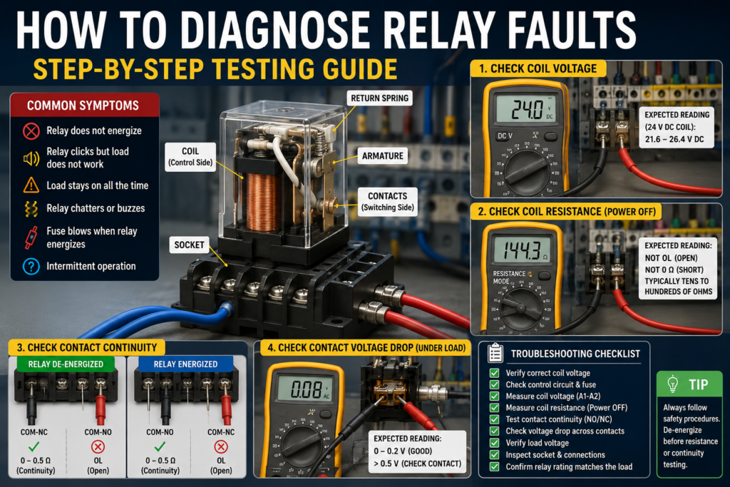
Common Relay Fault Symptoms
A faulty relay or relay circuit can cause many different symptoms.
Common examples include:
Load does not turn on
Load stays on all the time
Relay clicks but output does not work
Relay does not click
Relay chatters or buzzes
Relay coil gets hot
Fuse blows when relay energizes
PLC output turns on but relay does nothing
Motor contactor does not energize
Solenoid valve does not activate
Machine step does not continue
Random intermittent faults
The symptom tells you where to start, but it does not prove the relay is bad.
You need to test.
Basic Relay Parts to Understand
A standard electromechanical relay has two main parts:
Coil
The coil is the control side. When voltage is applied to the coil, the relay energizes.
Contacts
The contacts are the switching side. They open or close the load circuit.
A relay usually has contact types such as:
NO contact — Normally Open
Open when the relay is off. Closes when the relay energizes.
NC contact — Normally Closed
Closed when the relay is off. Opens when the relay energizes.
COM contact — Common
The shared terminal used with NO and NC contacts.
To diagnose relay problems properly, you usually need to test both sides: the coil and the contacts.
Tools Needed
For most relay fault diagnosis, you need:
Digital multimeter
Wiring diagram
Small screwdriver
Test leads or probe tips
Relay datasheet if available
Spare relay of the same type
Insulation tester, if testing cables or motor circuits
Clamp meter, if checking load current
The wiring diagram is very important. Without it, you may only be guessing.
Step 1: Identify the Relay Coil Voltage
Before testing anything, check the relay coil rating.
It may be printed on the relay body.
Common coil voltages include:
24 V DC
24 V AC
110 V AC
120 V AC
230 V AC
Do not assume.
A relay with a 24 V DC coil will not work correctly on 24 V AC.
A 230 V AC coil will not energize from 24 V DC.
A 24 V coil connected to 230 V will likely burn out.
What to check
Look for markings such as:
A1 / A2
Coil voltage
AC or DC symbol
Relay part number
Wiring diagram printed on the relay
On many industrial relays, the coil terminals are marked A1 and A2.
Step 2: Check If the Relay Coil Receives Voltage
This is one of the most important tests.
Set the multimeter to the correct voltage mode:
Use DC voltage for DC coils.
Use AC voltage for AC coils.
Measure directly across the relay coil terminals, usually A1 and A2.
Expected readings
For a 24 V DC relay coil, you should usually see around:
24 V DC when the relay should be ON
Usually acceptable: about 21.6–26.4 V DC, depending on equipment tolerance.
For a 230 V AC relay coil, you should usually see around:
230 V AC when the relay should be ON
Usually acceptable: about 207–253 V AC, depending on supply tolerance.
For a 120 V AC relay coil, you should usually see around:
120 V AC when the relay should be ON
Usually acceptable: about 108–132 V AC.
Always check the manufacturer’s specification if available.
What the reading means
If correct voltage is present and the relay does not energize, the relay coil may be bad or the relay may be mechanically stuck.
If no voltage is present, the problem is before the relay.
Possible causes:
PLC output not active
Broken wire
Blown fuse
Open emergency stop circuit
Open safety interlock
Bad push button
Bad selector switch
Missing neutral or 0V common
Bad terminal connection
If voltage is low, for example 24 V relay only receiving 12–16 V, the relay may chatter, buzz, or fail to pull in.
Possible causes:
Voltage drop
Weak power supply
Loose connection
Too much load on control supply
Long cable run
Bad common/neutral connection
Step 3: Listen and Feel for Relay Operation
When the relay energizes, most electromechanical relays make a small click.
This is not a complete test, but it gives useful information.
If the relay clicks
The coil is probably energizing and the armature is moving.
But the contacts may still be bad.
A relay can click and still fail to switch power because the contacts may be burned, worn, dirty, or mechanically damaged.
If the relay does not click
Possible causes:
No coil voltage
Wrong coil voltage
Burned coil
Mechanical jam
Relay not seated properly in socket
Broken socket terminal
Polarity issue on DC relay with diode
For DC relays with an LED or flyback diode, polarity may matter. Check A1 and A2 polarity.
Step 4: Test Relay Coil Resistance
This test must be done with power OFF.
Remove power from the circuit.
Verify the circuit is de-energized.
If needed, remove the relay from its socket.
Set the multimeter to resistance mode.
Measure across the coil terminals.
Expected readings
A good relay coil should show a resistance value.
It should not be OL/open circuit.
It should not be almost 0 Ω/short circuit.
Typical coil resistance depends heavily on relay size and coil voltage.
Approximate examples:
Small 24 V DC relay coil: often tens to hundreds of ohms
Small 120 V AC relay coil: often hundreds to several thousand ohms
Small 230 V AC relay coil: often several thousand ohms
Large contactor coils: values can be much lower than small control relays
These are only general ranges. Always compare with a known good relay or datasheet if possible.
What the readings mean
OL / infinite resistance
The coil is open. The relay coil is likely burned or broken.
Very low resistance, close to 0 Ω
The coil may be shorted. It may blow a fuse or overload the control supply.
Similar resistance to a known good relay
The coil is probably electrically okay.
Important: Some AC coils include electronics or suppressors, and some DC relays include LEDs or diodes. These can affect resistance readings.
Step 5: Test Relay Contacts With Continuity
This test must also be done with power OFF.
Remove the relay or isolate the contact circuit if needed.
Use the relay diagram printed on the relay body to identify COM, NO, and NC terminals.
Set the multimeter to continuity mode or low ohms.
De-energized relay readings
When the relay is OFF:
COM to NC should read closed.
Expected: usually 0–0.5 Ω or continuity beep.
COM to NO should read open.
Expected: OL or no continuity beep.
Energized relay readings
When the relay is ON:
COM to NO should read closed.
Expected: usually 0–0.5 Ω or continuity beep.
COM to NC should read open.
Expected: OL or no continuity beep.
You can energize the relay with the correct coil voltage on a safe test bench, or test it in the circuit if you are trained and it is safe to do so.
What bad readings mean
If COM to NO stays open when the relay energizes, the contact may be damaged or the relay mechanism may be faulty.
If COM to NC stays closed when the relay energizes, the contact may be welded or stuck.
If contact resistance is high, for example several ohms on a contact that should be closed, the contact may be worn, dirty, burned, or not fully closing.
Step 6: Check Contact Voltage Drop Under Load
Continuity testing is useful, but it does not always find bad contacts.
A relay contact can look okay with a multimeter continuity test, but fail under real load.
That is why voltage drop testing is very useful.
This test is done with the circuit energized and the load running, so only trained people should do it.
How to test
Set your multimeter to voltage mode.
Measure across the closed relay contact.
For example, place one probe on the input side of the contact and the other probe on the output side of the same contact.
Expected reading
Across a good closed relay contact, voltage drop should be very low.
Typical expected reading:
0 V to 0.1 V is very good.
Up to around 0.2 V may be acceptable for many small relay circuits.
Higher readings may indicate contact resistance.
For higher-current power contacts, readings depend on current and contact design, but a closed contact should still have a very low voltage drop.
Warning signs
If you measure:
0.5 V or more across a closed contact
This may indicate a poor contact, burned contact, loose terminal, or overloaded relay.
1 V or more across a closed contact
This is usually suspicious and should be investigated.
Several volts across a closed contact
The contact or connection is likely bad.
A bad relay contact may create heat. You may also see discoloration, melted plastic, or a burned smell.
Step 7: Check the Load Voltage
Sometimes the relay is working, but the load still does not operate.
In that case, check whether the load receives voltage.
For example, if a relay contact should power a solenoid valve, measure voltage at the solenoid coil.
If a relay contact should power a contactor coil, measure voltage at the contactor coil.
Expected readings
If the load is rated for 24 V DC, you should see around:
24 V DC when the relay output is ON
If the load is rated for 230 V AC, you should see around:
230 V AC when the relay output is ON
If voltage is present at the load but the load does not operate, the load may be faulty.
If voltage is present at relay output but not at the load, there may be a broken wire or loose terminal between the relay and the load.
If voltage is not present at relay output, the relay contact or upstream supply may be the problem.
Step 8: Check for Welded Contacts
A welded contact is a contact that has stuck closed, usually because of excessive current, arcing, short circuit, or wrong relay sizing.
Symptoms of welded contacts:
Load stays on even when relay coil is off
Motor or solenoid remains energized
Relay appears off, but output still has power
NO contact shows continuity when relay is de-energized
How to test
Turn power OFF and verify safe condition.
Measure continuity between COM and NO.
For a de-energized relay:
COM to NO should be OL/open.
If COM to NO shows continuity when the relay is removed or de-energized, the NO contact is likely welded closed.
Replace the relay.
Also investigate why it welded.
Possible causes:
Load current too high
Inductive load without suppression
Short circuit
Wrong relay rating
Too frequent switching
Relay used for motor load without proper contact rating
Do not just replace the relay without finding the cause.
Step 9: Check for Contact Wear or Burning
Relay contacts wear out over time.
This is especially true when switching inductive loads such as:
Contactors
Solenoid valves
Motor starters
Small motors
Transformers
Brake coils
Inductive loads create voltage spikes when switched off. These spikes cause arcing across the relay contacts.
Over time, this damages the contact surface.
Signs of bad contacts
Intermittent operation
Relay clicks but load does not always turn on
High voltage drop across contact
Heat around relay terminals
Burn marks
Melted relay base
Discoloration
Buzzing load contactor
Random machine stops
Best test
Use voltage drop testing under load.
A contact can pass a no-load continuity test but fail when current flows.
Step 10: Check the Relay Socket
Many plug-in relays are installed in sockets.
Sometimes the relay is good, but the socket is bad.
Common socket problems:
Loose terminal screw
Burned socket contact
Weak spring terminal
Relay not fully seated
Corrosion
Broken wire at socket
Heat damage
Wrong socket wiring
What to check
Remove the relay and inspect the socket.
Look for:
Dark marks
Melted plastic
Loose terminals
Bent pins
Burned smell
Signs of overheating
If possible, gently wiggle the relay while observing whether the fault appears. Be careful when doing this near live circuits.
A socket fault can cause intermittent problems that are very hard to find.
Step 11: Check Coil Suppression Devices
Many relay coils have suppression devices to protect PLC outputs and reduce voltage spikes.
Common suppression devices include:
Flyback diode
RC snubber
Varistor
LED indicator module
These parts can also fail.
Common problems
A shorted suppression diode can blow a fuse or prevent output operation.
A reverse-connected diode can short the DC supply when energized.
A failed LED module can cause confusing readings.
An RC snubber can allow small leakage current.
Multimeter clues
If a DC relay coil with diode module reads very low resistance in one direction, check polarity and suppression module.
If a PLC output turns on but voltage collapses when connected to relay coil, the coil or suppression device may be shorted.
If a relay stays slightly energized or LED glows faintly when off, leakage current through a PLC output or suppression circuit may be involved.
Step 12: Check AC Relay Buzzing or Chattering
A buzzing or chattering relay is a common fault.
This usually means the relay coil is not being held firmly.
Possible causes:
Low coil voltage
Wrong AC/DC coil type
Bad neutral connection
Loose wire
Voltage drop
Weak control transformer
Dirty or damaged armature
Mechanical wear
Frequency mismatch
Control signal rapidly switching on/off
What to measure
Measure voltage directly across the coil while the relay is buzzing.
For a 24 V DC coil, if you only see 15–19 V, that is too low.
For a 230 V AC coil, if you only see 160–190 V, that may be too low.
Also check if the control signal is stable. A PLC output or interlock may be turning on and off quickly.
Step 13: Check DC Relay Polarity
Some DC relays are polarity-sensitive.
This is usually because they have:
LED indicator
Flyback diode
Electronic module
Built-in suppression circuit
If polarity is wrong, the relay may not work correctly or may short the supply.
Expected polarity
Often:
A1 = positive
A2 = 0 V / negative
But do not assume. Check the relay markings.
If a plain DC relay coil has no diode or LED, it may not be polarity-sensitive.
Step 14: Check the Control Signal Source
If the relay coil does not receive voltage, test the device controlling it.
The relay may be controlled by:
PLC output
Push button
Selector switch
Limit switch
Safety relay
Timer relay
Pressure switch
Temperature controller
Float switch
Testing example: PLC output
If a PLC output should energize a 24 V DC relay:
Check PLC output LED.
Measure voltage from PLC output to 0 V.
Measure voltage directly across relay coil.
Check the 0 V common connection.
Check if output transistor or relay output is rated for the coil current.
Expected readings
PLC output OFF:
Output to 0 V should usually be around 0 V DC.
PLC output ON:
Output to 0 V should usually be around 24 V DC.
Relay coil A1 to A2 when ON:
Should usually be around 24 V DC.
If PLC output shows 24 V but relay coil does not, the problem is between PLC output and relay coil.
If relay coil gets 24 V but does not energize, suspect relay coil, socket, polarity, or mechanical fault.
Step 15: Check the Return Path or Neutral
A very common mistake is checking only the “live” side and forgetting the return path.
For DC circuits, the relay needs positive and 0 V.
For AC circuits, the relay needs live and neutral, or two control phases depending on the system.
If the return path is missing, the relay will not energize.
How to check
Measure directly across the coil terminals.
This is better than measuring only from A1 to ground.
Why?
Because A1 may have voltage, but A2 may not have a proper return.
If you measure from A1 to ground, you might see voltage and think the relay should work. But if A2 is open, the circuit is incomplete.
Always measure across A1 and A2.
Step 16: Check If the Relay Is Correctly Rated for the Load
A relay may fail early if it is switching a load that is too large.
Important ratings include:
Contact current rating
AC or DC switching rating
Inductive load rating
Motor load rating
Coil voltage rating
Number of switching cycles
Contact material
Inrush current rating
A relay rated for 10 A resistive load may not be suitable for a 10 A inductive motor load.
DC loads are often harder to switch than AC loads because DC arcs do not naturally cross zero like AC arcs.
Warning
Do not select a relay only by current rating.
Check whether the rating applies to:
AC load
DC load
Resistive load
Inductive load
Motor load
Lamp load
Solenoid load
The same relay may have very different ratings depending on load type.
Step 17: Check for Overheating
Relays can get warm, but they should not become excessively hot.
Causes of overheating:
Wrong coil voltage
Overvoltage on coil
Contact overloaded
Loose terminal
High contact resistance
Bad socket
Frequent switching
High ambient temperature
Poor panel ventilation
What to look for
Discolored plastic
Melt marks
Burned smell
Loose terminal screws
Brown marks on socket
Brittle wires
Hot relay compared with others
A thermal camera can be very useful here.
If one relay is much hotter than similar relays in the panel, investigate it.
Step 18: Swap With a Known Good Relay
For plug-in relays, one quick test is to swap with a known good relay of the same type.
But be careful.
Only swap if:
The relay part number is the same
The coil voltage is the same
The contact rating is suitable
The pin layout is the same
The circuit is safe to test
If the fault follows the relay, the relay is likely bad.
If the fault stays in the same socket, the problem is likely in the wiring, socket, control signal, or load.
This is a simple and effective method.
Step 19: Diagnose by Symptom
Relay does not energize
Check:
Coil voltage
Fuse
PLC output
Push button or switch
Emergency stop circuit
Neutral or 0 V common
Coil resistance
Socket connection
Correct coil voltage rating
Expected coil reading when ON:
Rated coil voltage across A1 and A2.
If rated voltage is present and no click, relay is likely faulty.
Relay energizes but load does not turn on
Check:
NO contact continuity
Voltage at relay output
Voltage at load
Load neutral/return
Contact voltage drop
Contact rating
Loose terminals
Burned contact
Expected reading:
Closed contact voltage drop should be near 0 V.
Load should receive rated voltage when relay output is ON.
Load stays on when relay is off
Check:
Welded NO contact
Wrong wiring
Backfeed from another circuit
PLC output stuck
Manual override active
Parallel circuit feeding load
Expected reading:
COM to NO should be OL when relay is de-energized.
Relay chatters
Check:
Low coil voltage
Loose wire
Weak power supply
Bad neutral/0 V
Wrong coil type
Unstable PLC output
Faulty interlock
Mechanical wear
Expected reading:
Coil voltage should remain stable near rated value.
Fuse blows when relay energizes
Check:
Shorted coil
Wrong coil voltage
Shorted suppression diode
Shorted load
Wrong wiring
Damaged cable
Expected reading:
Coil resistance should not be near 0 Ω.
Best Multimeter Tests Summary
Coil voltage test
Power ON, relay commanded ON.
Measure across A1 and A2.
Expected:
24 V DC relay: around 24 V DC
120 V AC relay: around 120 V AC
230 V AC relay: around 230 V AC
If voltage is correct but relay does not energize, suspect relay.
Coil resistance test
Power OFF.
Measure across A1 and A2.
Expected:
Not OL.
Not 0 Ω.
A normal resistance value depending on relay type.
Compare with datasheet or known good relay.
Contact continuity test
Power OFF.
Measure COM to NO and COM to NC.
Relay OFF:
COM-NO = OL
COM-NC = 0–0.5 Ω
Relay ON:
COM-NO = 0–0.5 Ω
COM-NC = OL
Contact voltage drop test
Power ON, load ON.
Measure across closed contact.
Expected:
Near 0 V.
Usually 0–0.2 V is normal for many small relay contacts.
More than 0.5–1 V is suspicious.
Load voltage test
Power ON, relay ON.
Measure at the load terminals.
Expected:
Load should receive its rated voltage.
Example:
24 V DC solenoid should receive around 24 V DC.
230 V AC coil should receive around 230 V AC.
Simple Relay Troubleshooting Flow
Use this order:
- Identify relay coil voltage and contact rating.
- Check if the relay should be energized.
- Measure voltage across the coil.
- If voltage is missing, troubleshoot the control circuit.
- If voltage is correct but relay does not click, test or replace the relay.
- If relay clicks, test the contacts.
- Check voltage at relay output.
- Check voltage at the load.
- Check contact voltage drop under load.
- Inspect relay socket, terminals, and wiring.
- Check load current and relay rating.
- Replace the relay only after confirming the cause.
Final Thoughts
Relay faults are common in industrial automation, but the relay itself is not always the problem.
A good troubleshooting method is to separate the circuit into two parts:
Control side: coil, PLC output, switches, interlocks, control voltage.
Power side: contacts, load supply, wiring, load device, contact rating.
Start by checking whether the coil receives the correct voltage. Then check whether the contacts actually switch the load. After that, check the load voltage, socket, terminals, and wiring.
The best relay troubleshooting tests are:
Coil voltage test
Coil resistance test
Contact continuity test
Contact voltage drop test
Load voltage test
Socket and wiring inspection
If you follow these steps, you can diagnose most relay faults logically instead of guessing.
A relay is simple, but in automation, simple parts can stop big machines.