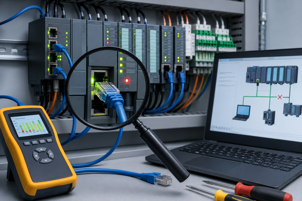
A PLC fault message is not the problem itself.
It is a clue.
Sometimes it is a very good clue: I/O module missing in slot 4. Other times it feels like the controller is speaking in riddles—an unfamiliar hexadecimal code, a flashing red LED and a description vague enough to blame almost anything.
Still, the fault should never be cleared blindly just to see whether the machine starts again. That occasionally works, sure. It also wipes away useful evidence and leaves the real cause waiting for a less convenient moment to return.
When a PLC stops, begin by asking three questions:
- What exactly did the controller detect?
- What was happening immediately before the fault?
- Is the reported fault the root cause, or only the final consequence?
That small change in approach makes PLC troubleshooting far more efficient.
What Is a PLC Fault Code?
A PLC fault code is a diagnostic message generated when the controller detects an abnormal condition.
Depending on the system, the fault may relate to:
- CPU operation
- Program execution
- Memory
- I/O modules
- Network communication
- Power supply
- Hardware configuration
- Motion control
- Safety functions
- Watchdog timing
- Arithmetic instructions
- Firmware compatibility
The code usually includes a number, name or category together with a short description.
For example, a controller might report:
- Division by zero
- I/O connection timeout
- Requested module not found
- Invalid array index
- Watchdog timeout
- Nonrecoverable hardware fault
- Duplicate network address
- Program signature mismatch
- Memory-card error
The message is not always written in plain language. Some manufacturers display fault classes, subcodes or event identifiers that must be checked against the programming-software help system or technical manual.
Write down the complete message before doing anything else.
Not just “communication fault.”
Record the actual code, affected module, slot number, timestamp and description. Tiny details matter.
Major Faults and Minor Faults
Most PLC platforms separate faults into at least two broad categories:
- Major faults
- Minor faults or warnings
The exact terminology differs by manufacturer, but the basic idea is similar.
What Is a Major PLC Fault?
A major fault is serious enough to stop normal controller execution.
The PLC may:
- Enter STOP or PROGRAM mode
- Disable outputs
- Halt part of the application
- Stop scanning the user program
- Trigger a controller fault routine
- Require manual acknowledgement
- Refuse to return to RUN mode
Common causes include:
- Program execution errors
- Watchdog timeouts
- Invalid instructions
- Memory corruption
- Critical hardware failure
- Mandatory I/O module mismatch
- Arithmetic overflow
- Division by zero
- Safety-system faults
- Controller firmware problems
When a major fault occurs, the machine usually stops because the PLC can no longer guarantee correct program execution.
That is inconvenient, but it is often safer than allowing the controller to continue with unreliable data.
What Is a Minor PLC Fault?
A minor fault does not normally stop the processor immediately.
The controller may remain in RUN mode while recording a warning or diagnostic event.
Typical examples include:
- Temporary communication loss
- Recoverable I/O interruption
- Battery warning
- Noncritical module diagnostic
- Instruction parameter warning
- Tag reference problem
- Time synchronization issue
- Network retry or timeout
- Loss of optional equipment
- Memory usage warning
Minor does not mean irrelevant.
A warning that appears once during maintenance may not be serious. The same warning appearing fifty times per shift is telling you something is deteriorating.
Intermittent faults often begin as minor warnings before developing into a full machine stoppage.
Where to Find PLC Fault Information
The fault location depends on the PLC platform, but there are several common places to check.
Controller Properties
Most programming packages include a controller or CPU properties window.
This may show:
- Current operating mode
- Active fault
- Fault type
- Fault code
- Fault description
- Time of occurrence
- Controller status
- Memory condition
- Firmware version
For Rockwell Automation controllers, fault information may appear in Controller Properties, the Major Faults section or controller status information.
For Siemens controllers, useful information is often found in the diagnostic buffer, online diagnostics or device view.
Other manufacturers provide equivalent CPU diagnostic screens.
Diagnostic Buffer or Event Log
The diagnostic buffer records events in chronological order.
This is often more useful than looking only at the active fault because it shows what happened before the controller stopped.
You might see a sequence such as:
- Remote I/O station disconnected.
- Communication module entered fault state.
- Required input data became unavailable.
- CPU entered STOP mode.
The CPU STOP message was the final result. The first communication event may be the actual starting point.
Always work backward through the timeline.
Module Diagnostics
A fault may belong to one particular module rather than the CPU itself.
Open the diagnostics for:
- Digital input modules
- Digital output modules
- Analogue modules
- Communication cards
- Motion modules
- Safety modules
- Remote I/O adapters
- VFD communication interfaces
Useful information may include:
- Channel fault
- Short circuit
- Wire break
- Missing field power
- Overtemperature
- Configuration mismatch
- Connection timeout
- Module ownership problem
- Incorrect firmware revision
The controller may only report that an I/O connection failed. The module diagnostics often explain why.
HMI Alarm History
An HMI alarm list can help establish what happened before the PLC fault.
For example:
- Low air pressure appeared first.
- Several cylinders failed to reach position.
- A sequence timer expired.
- The controller later generated a machine fault.
The PLC code alone may not reveal that the real problem began with a pneumatic pressure drop.
Managed-Switch and Network Logs
For Ethernet-related faults, check the network infrastructure too.
A managed switch may record:
- Port disconnection
- Ring failure
- Excessive errors
- Duplicate IP address
- Link-speed change
- Broadcast storm
- Fibre-optic interruption
- Device reconnection
A PLC communication fault may be completely accurate while the actual cause is a loose cable or failing switch port several cabinets away.
Record the Exact Fault Before Clearing It
This should become a habit.
Before resetting anything, record:
- Fault code
- Full description
- PLC mode
- Date and time
- Affected program or task
- Rack, slot and channel
- Module name
- Machine condition
- Operator observations
- Status LEDs
- Recent maintenance work
- Whether the fault happened during startup or normal operation
Take screenshots where site rules allow it.
A written note saying “PLC stopped again” is almost useless.
A useful note looks more like this:
14:27 — CPU entered STOP. Fault code 16#0002:3500. Remote PROFINET device
ET200_Station_3reported unavailable approximately four seconds earlier. Machine was closing clamp station 2. BF LED flashing on remote interface module.
Now the next person has something concrete to investigate.
Do Not Clear the Fault First
The temptation is understandable.
Production is waiting. The supervisor wants the machine running. Somebody says, “Just reset it and see.”
Sometimes the controller returns to RUN and the machine continues.
Unfortunately, clearing the fault too early can remove:
- Temporary diagnostic data
- First-fault information
- Module status
- Event sequence
- Buffer entries
- Useful timestamps
- Evidence of an intermittent condition
It can also create the impression that the problem has been repaired when nothing has actually changed.
Read first. Record second. Reset later.
Identify the First Fault, Not Just the Last One
Machines often generate several errors from one original failure.
Imagine that a remote I/O station loses power.
The sequence may be:
- Remote I/O communication is lost.
- Multiple inputs become unavailable.
- Motor feedback disappears.
- Sequence timers expire.
- The HMI shows several actuator faults.
- The PLC enters a fault state.
If you begin with the final actuator alarm, you may waste an hour checking a perfectly healthy motor.
The first meaningful event is usually the most valuable one.
This is why timestamps matter. Arrange alarms and diagnostic events in order, then find the earliest abnormal condition.
Not every early message is the root cause, but it gives you a sensible place to begin.
Common PLC Fault Categories
Programming and Instruction Faults
Program faults occur when the controller encounters an operation it cannot execute safely.
Examples include:
- Division by zero
- Invalid array index
- Indirect address outside the allowed range
- Arithmetic overflow
- Invalid jump or subroutine call
- Incorrect instruction parameters
- Excessive recursion
- Corrupted data structure
- Motion instruction conflict
These faults are often linked to unusual process values.
A calculation may work normally for months, then fail when a sensor unexpectedly returns zero or a recipe value exceeds its expected range.
Do not only fix the immediate instruction. Ask why the unexpected value was allowed to reach it.
A better solution may include:
- Input validation
- Range checks
- Divide-by-zero protection
- Array-bound checks
- Alarm handling
- Default fallback values
Clearing the fault without improving the logic usually means it will return.
Watchdog Timeout
A watchdog fault occurs when the PLC takes too long to complete a task or program scan.
Possible causes include:
- Infinite loop
- Excessive loop iterations
- Long-running calculations
- Program change that increased execution time
- Communication instruction waiting too long
- Motion task overload
- Controller overloaded by too many tasks
- Faulty module affecting execution
- Inappropriate task priority
Check the task execution time and maximum scan time.
If the fault began after a program modification, compare the changed logic with the previous backup. A loop that looked harmless on screen may be consuming the entire scan.
Increasing the watchdog limit can hide the symptom, but it should not be the first response.
Find out why the task exceeded the expected time.
I/O Configuration Faults
The PLC project contains an expected hardware configuration.
If the real hardware does not match it, the controller may report:
- Module missing
- Wrong module type
- Incorrect slot
- Electronic keying mismatch
- Firmware mismatch
- Invalid channel configuration
- Connection request rejected
- Module ownership conflict
This often happens after replacing hardware.
A replacement module may look identical but have:
- A different catalogue number
- Different firmware
- Different channel count
- Different revision
- Different safety signature
- Different communication settings
Compare the physical label with the project configuration exactly.
“Almost the same module” can be enough to keep an entire rack offline.
Communication Faults
PLC communication faults may involve:
- Remote I/O
- HMI
- VFD
- Servo drive
- Another PLC
- SCADA system
- Ethernet switch
- Serial network
- Fieldbus device
Likely causes include:
- Loose cable
- Damaged connector
- Duplicate IP address
- Incorrect subnet
- Missing PROFINET device name
- Device power loss
- Switch failure
- Network noise
- Configuration mismatch
- Incorrect node address
- Termination problem
- Firmware incompatibility
- Excessive network traffic
Do not assume the PLC communication card is faulty just because it reports a timeout. Often it is simply the messenger.
Check the physical network first.
Power-Supply Faults
Unstable power causes some of the most confusing PLC behaviour.
Symptoms may include:
- Random controller restart
- Lost communication
- Corrupted I/O status
- Repeated boot cycle
- Memory-card error
- Module disconnection
- Faults that appear during contactor operation
- Problems only when a large load starts
Measure the supply voltage at the PLC terminals.
A 24 V DC power supply may show the correct voltage with no load and collapse briefly when several solenoids energize.
Check:
- Power-supply capacity
- Loose terminals
- Blown or resistive fuses
- Voltage dips
- Shared loads
- Grounding
- Ripple
- Failing UPS
- Cabinet temperature
A fast voltage dip may be too brief for a standard multimeter to display. A recording meter or oscilloscope may be needed for stubborn intermittent problems.
Memory and Storage Faults
PLC memory faults can involve:
- Corrupted user program
- Defective memory card
- Card removed during operation
- Incompatible project
- Interrupted firmware update
- Insufficient memory
- Failed battery or capacitor backup
- Nonvolatile-memory error
Before replacing the CPU, inspect the memory card and compare the installed project with a known working backup.
Never format or rewrite a PLC memory card without confirming that a valid program backup exists.
One careless click can turn a recoverable fault into a much longer shutdown.
Hardware Faults
A hardware fault may indicate:
- CPU failure
- Backplane problem
- Damaged I/O module
- Overtemperature
- Internal power-supply failure
- Communication-processor failure
- Shorted field wiring
- Environmental damage
Look for patterns.
Does the fault remain with the same slot when modules are exchanged? Does it follow the module? Does it appear only when a particular output energizes?
Swapping components can be useful, but only when performed safely and methodically. Change one item at a time and document the result.
Randomly exchanging three modules at once may restore operation, yet leave you with no idea which one was defective.
Major Fault Troubleshooting Procedure
When a PLC enters a major fault state, use a structured process.
1. Make the Machine Safe
Before touching the program or hardware:
- Stop hazardous motion
- Inform operators
- Isolate energy where required
- Apply lockout/tagout when necessary
- Confirm stored energy is controlled
A PLC fault does not guarantee that every actuator is harmless.
2. Observe the Controller LEDs
Record the status of:
- RUN
- STOP
- ERROR
- FAULT
- I/O
- COMM
- BF
- SF
- MAINT
Do this before cycling power.
LED combinations can reveal whether the problem involves the CPU, memory, communication or field I/O.
3. Go Online With the PLC
Connect using the appropriate programming software.
Confirm that you are connected to the correct controller. This sounds obvious until a factory contains six identical machines using similar IP addresses.
4. Read the Complete Fault Information
Record the active code and description.
Open:
- Controller diagnostics
- Event history
- Diagnostic buffer
- Task status
- Module diagnostics
- Network diagnostics
5. Find the Earliest Related Event
Work backward through the timeline.
Identify what changed immediately before the major fault.
6. Compare With Electrical Drawings
Check the affected device in the wiring diagrams.
A controller may report missing feedback because:
- A sensor has failed
- A fuse has opened
- A common wire is loose
- Field power is absent
- A terminal has backed out
- The input module is damaged
What appears to be software trouble may be ordinary wiring trouble.
It often is.
7. Check Recent Changes
Ask whether anyone recently:
- Replaced a module
- Downloaded a program
- Changed a recipe
- Updated firmware
- Moved a cable
- Added a device
- Modified network settings
- Worked inside the cabinet
- Restored an old backup
The timing of a fault frequently points straight toward the cause.
8. Correct the Underlying Problem
Repair the actual issue before resetting the controller.
Examples:
- Replace damaged cable
- Correct the program instruction
- Restore field power
- Assign the proper device name
- Install compatible firmware
- Reconfigure the module
- Replace failed hardware
- Correct an invalid recipe value
9. Clear the Fault
Once the cause has been corrected, clear or acknowledge the controller fault according to the manufacturer’s procedure.
The controller may need to be placed back into RUN mode manually.
10. Test Under Controlled Conditions
Test the machine in manual or maintenance mode first.
Confirm:
- Inputs change correctly
- Outputs respond normally
- Communication remains stable
- No fault returns
- Safety functions operate
- Automatic sequence is ready
Do not jump straight into full-speed production when a slower controlled test is possible.
Intermittent PLC Faults
Intermittent faults are the ones that make good technicians stare at cabinets in silence.
The machine runs perfectly while you are standing beside it. Then it stops fifteen minutes after you leave.
These faults are often related to:
- Loose terminals
- Damaged moving cables
- Electrical noise
- Marginal power supply
- Overheating
- Vibration
- Moisture
- Communication errors
- Failing connector
- Hardware beginning to break down
Do not dismiss a fault simply because it reset successfully.
Intermittent does not mean imaginary.
Use Watch Tables and Monitor Windows
Most PLC software allows technicians to monitor several tags together.
Depending on the platform, this may be called:
- Watch table
- Data monitor
- Trend
- Tag monitor
- Variable table
- Online table
Monitor values such as:
- Supply status
- Communication bits
- Sequence step
- Interlocks
- Sensor feedback
- Output commands
- Timer values
- Fault counters
- Cycle time
- Motor current
- Network health
Watching several related signals at once can reveal the order in which conditions fail.
For example:
- Remote I/O health bit turns off.
- Sensor feedback disappears.
- Sequence timer begins timing.
- Machine alarm activates.
That is far more useful than staring at one rung and waiting for something to change.
Use Trends for Problems That Happen Too Quickly
Some events happen too quickly for the human eye to catch online.
A signal may turn off for 50 milliseconds and return before anyone notices.
Trend tools can record:
- Voltage values
- Pressure
- Position
- Communication state
- Scan time
- Sensor status
- Motor current
- Fault bits
For intermittent faults, configure trigger conditions so the software captures data before and after the event.
This can expose short voltage dips, bouncing sensors or temporary communication loss.
Cross-Reference Faulted Tags
When a fault references a tag or address, use the software’s cross-reference tool.
Find every place where the tag is:
- Read
- Written
- Aliased
- Produced
- Consumed
- Moved
- Calculated
- Reset
- Used as an array index
A variable that appears simple may be written from several routines.
Do not assume the visible rung is the only place controlling it.
Cross-referencing is particularly important when dealing with:
- Sequence numbers
- Fault-reset bits
- Communication flags
- Mode commands
- Internal permissives
- Motion commands
Check the Electrical Drawings
PLC software shows what the controller sees.
Electrical drawings show how the signal reaches it.
Use both.
For an input fault, trace:
- Power supply
- Fuse
- Sensor
- Junction box
- Terminal strip
- Cable
- PLC input channel
- Input common
For an output fault, trace:
- PLC output channel
- Output common
- Fuse
- Interposing relay
- Safety contact
- Terminal strip
- Field cable
- Solenoid or contactor coil
A program fault and a wiring fault can look surprisingly similar from the HMI.
Document Temporary Forces and Bypasses
Temporary forces should never become invisible permanent features.
When a force or bypass must remain during controlled maintenance, document:
- Forced tag
- Forced state
- Reason
- Date and time
- Person responsible
- Expected removal time
- Associated risk controls
Add a clearly visible maintenance note according to site procedure.
Then remove the force as soon as the test is complete.
Forgotten forces can cause months of strange machine behaviour because the controller keeps seeing an artificial condition.
Keep Good Program Backups
Before making changes, create a backup.
After making tested and approved changes, create another backup.
Use filenames that mean something.
Poor example:
Machine_Final_New_ReallyFinal2Better example:
Line3_Packer_2026-07-22_Before_FaultFixand:
Line3_Packer_2026-07-22_After_IOTimeoutFixInclude change notes describing:
- Fault investigated
- Logic modified
- Hardware replaced
- Parameter changed
- Person making change
- Test completed
Future you—or the next technician—will be grateful.
Do Not Upload an Old Program Without Checking
Restoring an old backup can solve a corrupted-program problem, but it can also erase legitimate machine changes.
Before downloading, compare:
- Program timestamp
- Hardware configuration
- Recipe values
- Drive parameters
- Safety signatures
- Network addresses
- HMI version
- Recent modifications
The “working backup” from two years ago may predate a replaced drive, new sensor or safety modification.
Confirm what will be overwritten.
Common Mistakes When Troubleshooting PLC Faults
Clearing the code without recording it
Once cleared, the best evidence may be gone.
Replacing the PLC first
The CPU is often blamed because it displays the fault. Usually it is reporting a problem elsewhere.
Ignoring minor faults
Repeated warnings can reveal developing cable, power or network problems.
Changing several things at once
You may restore the machine but never identify the true cause.
Increasing watchdog time immediately
This can hide a slow or looping program instead of fixing it.
Testing under full production pressure
Controlled testing is safer and usually produces clearer results.
Trusting only the HMI message
HMI alarms may be simplified, delayed or based on secondary symptoms.
Assuming the fault description is the root cause
A missing input may be caused by a broken sensor, failed power supply or remote-I/O disconnect.
Quick PLC Fault Troubleshooting Table
| Fault symptom | Possible causes |
|---|---|
| PLC enters STOP immediately after download | Program error, hardware mismatch or incompatible firmware |
| CPU faults during a certain sequence step | Invalid data, array index error, calculation fault or motion conflict |
| Remote I/O repeatedly disconnects | Power issue, cable damage, switch fault, duplicate address or network noise |
| Fault appears when a large motor starts | Voltage dip, grounding problem or electromagnetic interference |
| Controller restarts randomly | Unstable power, overheating, hardware failure or memory problem |
| Fault returns after several hours | Temperature, vibration, cable movement or marginal power supply |
| Module fault after replacement | Wrong module type, firmware or configuration |
| HMI alarms appear but PLC remains healthy | HMI communication, tag mapping or network fault |
| Minor communication faults accumulate | Damaged cable, overloaded network, loose connector or failing switch |
| PLC fault clears but returns under load | Root cause was not corrected |
A Better Fault-Finding Mindset
PLC diagnostics work best when treated like evidence rather than instructions.
The controller may tell you that a remote module disappeared. It cannot always tell you whether the cause was a failed power supply, broken cable, loose terminal or somebody unplugging the switch.
Use the fault code to narrow the search.
Then verify the real condition using:
- Multimeter measurements
- Status LEDs
- Electrical drawings
- Network diagnostics
- Watch tables
- Trend recordings
- Module information
- Operator observations
- Program cross-references
The fault code points toward the area. Troubleshooting still requires judgment.
Final Thoughts
A PLC usually faults for a reason.
The message may be awkwardly worded, buried inside a diagnostic window or represented by a code that requires a manual, but it is still one of the most valuable clues available.
Do not erase that clue too early.
Record the complete fault. Review the event history. Find the first abnormal condition, then compare the controller information with the real machine—wiring, power, sensors, communication and hardware.
Fix the cause before clearing the message.
And when the fault is intermittent, take it seriously. A brief communication dropout or occasional power warning may be the machine giving you an early heads-up before a much longer shutdown.
The PLC is rarely being mysterious on purpose.
Usually, it is trying to tell you exactly where to start looking.