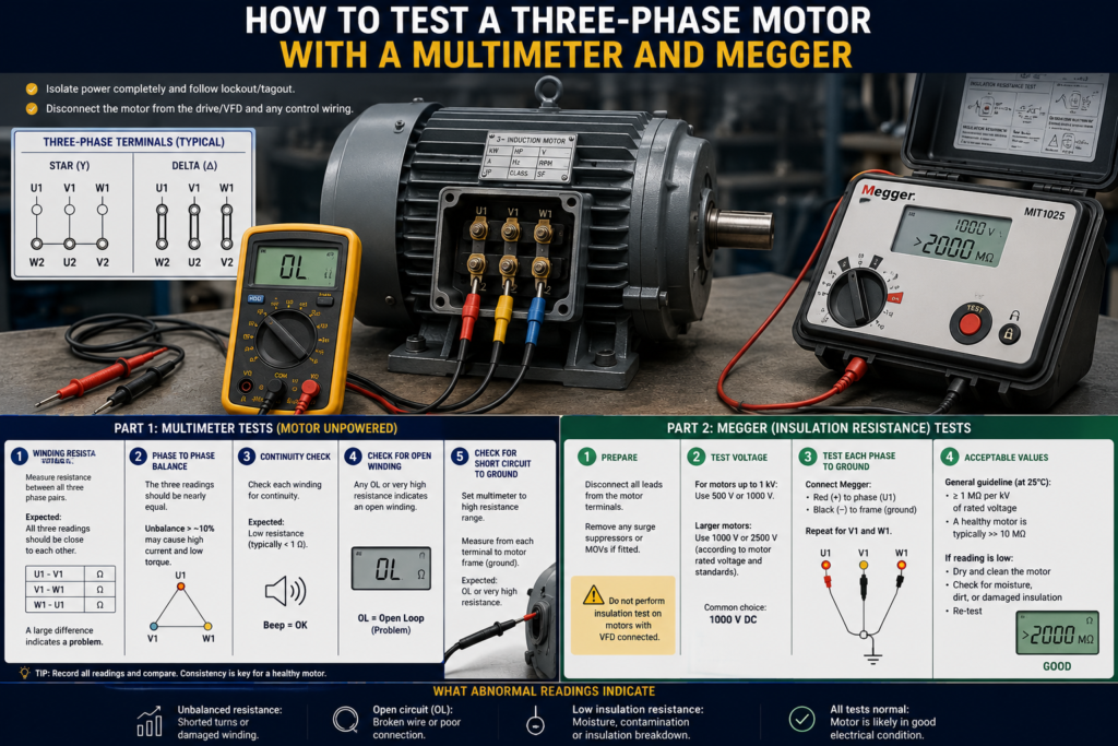
A three-phase motor can look perfectly normal from the outside and still have an open winding, poor insulation or a connection that will fail as soon as power is applied.
Two basic instruments can reveal many of these problems:
- A digital multimeter for continuity and winding-resistance checks
- An insulation-resistance tester, commonly called a Megger, for testing insulation to earth
These tests are useful, but they do not detect every possible motor fault. A motor can pass a basic resistance test and still have shorted turns, cracked rotor bars, damaged bearings or problems that appear only while running.
The goal is not to produce one magical “good motor” reading. It is to gather several pieces of evidence and compare them logically.
Work Safely Before Testing
The motor must be completely disconnected from electrical power before resistance or insulation testing.
Before beginning:
- Stop the machine.
- Isolate and lock out the supply.
- Verify the absence of voltage with an approved tester.
- Disconnect the motor from the contactor, soft starter or VFD.
- Confirm that the driven equipment cannot move unexpectedly.
- Record the existing terminal-link positions before removing them.
Never apply a Megger test voltage through a VFD, PLC input, thermistor relay, encoder or other electronic equipment. Insulation-test voltage can seriously damage connected electronics.
A VFD can also retain dangerous DC voltage after its incoming supply is removed. Wait for the discharge time stated by the manufacturer and verify that the DC bus is safe.
What the Multimeter and Megger Actually Test
A multimeter uses a very small test voltage. It is suitable for checking:
- Open windings
- Basic winding resistance
- Continuity
- Obvious phase-to-phase shorts
- Obvious connections to the motor frame
A Megger applies a much higher controlled DC voltage. It tests whether current leaks through insulation between:
- A motor winding and the frame
- One winding and another winding, where the phases can be separated
- A motor cable conductor and earth
A normal multimeter may display an open circuit between a winding and the frame even when the insulation is weak. It simply does not apply enough voltage to stress the insulation properly.
That is why both instruments are useful.
Step 1: Inspect the Motor Before Measuring
Open the motor terminal box and look for:
- Burned or darkened terminals
- Loose nuts
- Damaged terminal links
- Moisture
- Oil or dust contamination
- Cracked cable insulation
- A burnt winding smell
- Signs of overheating
- Corrosion around the cable gland
Turn the shaft by hand where this is safe and possible. It should rotate smoothly without severe grinding, scraping or excessive resistance.
An electrical test will not diagnose a seized bearing or jammed gearbox.
Step 2: Identify the Motor Terminals
A common six-terminal IEC motor is marked:
- U1 and U2
- V1 and V2
- W1 and W2
Each pair belongs to one stator winding.
The motor may currently be linked in star or delta. Photograph and label the wiring before removing anything.
Remove the terminal links when you want to test each winding separately. Leaving the links installed connects the windings together and can produce readings that are difficult to interpret.
Some motors have only three accessible terminals because the star or delta connection is made internally. You can still compare terminal-to-terminal resistance, but you cannot isolate each winding without opening the motor internally.
Step 3: Check the Multimeter First
Before testing the motor, place the multimeter in its lowest resistance range and touch the probes together.
The meter should show a very low value.
The resistance of the leads may be significant compared with the resistance of a small motor winding. Record the lead resistance or use the meter’s relative-zero function if it has one.
Also confirm the meter is functioning correctly before relying on an open-circuit reading.
Step 4: Measure Each Motor Winding
With the links removed, measure:
- U1 to U2
- V1 to V2
- W1 to W2
Record all three readings.
The exact resistance depends on the motor’s power, voltage, winding design and temperature. A larger motor may have such a low winding resistance that an ordinary multimeter cannot measure it accurately.
The important result is balance.
The three winding readings should be very similar. Fluke recommends looking for balanced comparative resistance across all three stator phases and warns that a difference greater than a few percent can indicate that the motor may be unsafe to energise.
What the Results May Mean
All three readings are similar:
The windings are at least continuous and reasonably balanced.
One winding shows an open circuit:
There may be a broken winding, failed internal joint or loose terminal connection.
One winding has noticeably higher resistance:
Check for a loose terminal, damaged joint or partially open winding.
One winding has noticeably lower resistance:
A winding fault or shorted section may be present, although an ordinary multimeter cannot reliably detect every turn-to-turn short.
All readings appear almost zero:
The motor may simply have very low-resistance windings. Use a low-resistance ohmmeter before deciding that they are shorted.
Winding resistance should ideally be compared at a similar motor temperature because copper resistance changes with temperature.
Step 5: Check for Continuity to the Motor Frame
Keep the multimeter in resistance mode.
Place one probe on a clean, unpainted section of the motor frame. Test the other probe against:
- U1
- V1
- W1
- U2
- V2
- W2
A healthy motor should not show normal electrical continuity between a winding terminal and the frame.
A low-resistance reading indicates a serious earth fault.
However, an open reading on a multimeter does not prove that the insulation is healthy. Continue with an insulation-resistance test.
Step 6: Disconnect Sensitive Accessories
Before using the Megger, identify anything else connected inside the terminal box.
Possible accessories include:
- PTC thermistors
- PT100 sensors
- Anti-condensation heaters
- Encoder wiring
- Brake coils
- Surge suppressors
- Temperature switches
- VFD motor cables
Disconnect or isolate these according to the motor manufacturer’s procedure.
Do not apply a 500 V insulation test to a low-voltage temperature sensor simply because its wires enter the same terminal box.
Step 7: Select the Correct Megger Test Voltage
The correct test voltage depends on the motor’s rated voltage and the manufacturer’s instructions.
For many low-voltage motors rated below 1,000 V, a 500 V DC insulation test is commonly specified. WEG’s general motor guidance lists 500 V DC for windings rated below 1,000 V, with higher test voltages used for higher-voltage machines.
Do not automatically select the highest voltage available.
Higher test voltage is not always better. Using the wrong setting can overstress insulation or damage connected equipment. Follow the motor manual, site procedure and applicable standard.
Step 8: Test Each Winding to Earth
Whenever the motor allows the windings to be separated, test them individually.
For the first winding:
- Connect the Megger’s earth lead to the clean motor frame.
- Connect the test lead to U1 or U2.
- Ground the other two windings to the motor frame.
- Apply the selected test voltage.
- Hold the test for the specified time, commonly one minute.
- Record the resistance and motor temperature.
Repeat for the V and W windings.
WEG recommends isolating and testing each phase separately where possible, while grounding the other phases and the motor frame.
If the motor has only three terminals and its internal connection cannot be separated, join the three terminals together and test the complete winding assembly to the frame.
Step 9: Discharge the Windings
Motor windings can retain electrical charge after an insulation test.
Allow the tester to complete its automatic discharge cycle, where provided. Then confirm that the winding is discharged before touching the terminals.
Fluke insulation testers include a discharge function because the circuit can remain charged after testing.
On larger machines, follow the manufacturer’s specified grounding time. Do not assume that removing the test leads makes the motor immediately safe.
How to Interpret Megger Readings
In general, higher insulation resistance is better.
A healthy dry low-voltage motor may measure hundreds or thousands of megohms. A wet, dirty or deteriorated motor may produce a much lower reading.
Still, there is no single value that should be applied blindly to every motor.
Insulation resistance changes with:
- Winding temperature
- Humidity
- Motor size
- Rated voltage
- Insulation system
- Dirt and contamination
- How long the test voltage is applied
WEG’s general guidance for motors rated up to 1.1 kV classifies values up to 5 MΩ, corrected to 40°C, as dangerous, while values above 100 MΩ are considered good or better. WEG also states that these are reference values and recommends recording measurements over time.
The motor manufacturer’s limit should take priority.
Compare the Three Phases
When the phases are separately accessible, their insulation readings should be in the same general range.
One phase reading far below the others suggests localised contamination, moisture or insulation damage.
Look at the Trend
A motor that measured 2,000 MΩ last year and 150 MΩ today may still appear to have “high resistance,” but the sharp decline is important.
Trending readings taken at similar temperatures is often more useful than relying on a single pass-or-fail number. Megger recommends winding-resistance and insulation testing as part of a wider condition-monitoring process rather than treating one test as conclusive.
Can a Motor Pass These Tests and Still Be Faulty?
Yes.
A multimeter and Megger may not reliably identify:
- Shorted turns within one winding
- Cracked rotor bars
- Rotor eccentricity
- Bearing damage
- Problems appearing only when hot
- Vibration or alignment faults
- Weak insulation that fails only under switching surges
- Mechanical overloading
Further investigation may require:
- Surge comparison testing
- Low-resistance winding measurement
- Motor-current signature analysis
- Vibration analysis
- No-load and loaded current tests
- Bearing inspection
- Thermal imaging
One good reading does not prove the complete motor is healthy. One clearly bad reading, however, is enough reason not to energise it.
Quick Testing Checklist
- Lock out and verify zero voltage.
- Disconnect the motor from the starter or VFD.
- Photograph and remove star or delta links.
- Inspect terminals and cable condition.
- Measure U1–U2, V1–V2 and W1–W2.
- Compare all three winding resistances.
- Check each terminal against the frame with a multimeter.
- Disconnect sensors and electronic accessories.
- Select the manufacturer-approved Megger voltage.
- Test each winding to the motor frame.
- Record the reading, test time and temperature.
- Discharge and ground the windings before reconnection.
Final Thoughts
Testing a three-phase motor is mostly about comparison.
The three winding resistances should be closely balanced. There should be no low-resistance path from a winding to the frame. Insulation resistance should be high, reasonably balanced and consistent with the motor manufacturer’s limits and previous test results.
Do not reconnect the terminal links from memory. Use your photograph, the motor nameplate and the connection diagram.
And do not use a successful Megger test as proof that every part of the motor is healthy. It tells you about insulation condition—not bearings, rotor bars or the behaviour of the motor under load.