A contactor is one of the most common components inside an industrial electrical panel.
It is used to switch motors, heaters, pumps, fans, compressors, conveyors, and other higher-power loads. In simple words, a contactor is like a heavy-duty relay.
When a contactor fails, the machine may stop completely.
But here is the important part:
A contactor problem does not always mean the contactor itself is bad.
Sometimes the real problem is in the control circuit, overload relay, PLC output, wiring, coil voltage, auxiliary contact, motor, or mechanical load.
So the best way to troubleshoot a contactor is to test it step by step.
Safety First
Contactors often switch dangerous voltages.
You may be working near:
24 V DC control circuits
110 V AC control circuits
230 V AC control circuits
400 V three-phase circuits
Motor power terminals
Stored electrical energy
Moving machine parts
Before testing, always follow proper safety procedures.
Important rules:
Do not touch live terminals.
Use lockout/tagout before resistance or continuity testing.
Never measure resistance on a live circuit.
Use a properly rated multimeter.
Use insulated probes.
Do not bypass safety devices.
Do not force a contactor closed by hand on a live machine.
Follow your company and local electrical safety rules.
This guide is for educational purposes. Live electrical troubleshooting should only be done by qualified people.
Common Contactor Fault Symptoms
A bad contactor or contactor circuit can cause many different symptoms.
Common examples include:
Motor does not start
Contactor does not pull in
Contactor pulls in but motor does not run
Contactor chatters or buzzes
Contactor drops out randomly
Motor runs on two phases
Motor overload trips
Fuse or breaker trips when contactor closes
Contactor coil burns out
Contactor gets very hot
Main contacts are burned or welded
Auxiliary contact does not change state
PLC output is ON but contactor is not energizing
Machine shows “motor fault” or “contactor feedback fault”
Each symptom points to a possible area, but you still need to test.
Main Parts of a Contactor
Before troubleshooting, understand the main parts.
A contactor usually has:
Coil terminals
Main power contacts
Auxiliary contacts
Moving armature
Fixed and moving core
Return spring
Arc chamber
Control terminals
Power terminals
Overload relay, if installed with a motor starter
The two most important areas are:
Control side — the coil and control wiring
Power side — the main contacts and load wiring
A good troubleshooting method separates these two sides.
Step 1: Identify the Contactor Coil Voltage
First, check the coil voltage printed on the contactor.
Common coil voltages include:
24 V DC
24 V AC
110 V AC
120 V AC
230 V AC
400 V AC
The coil terminals are usually marked:
A1 and A2
Do not guess the coil voltage.
A 24 V DC coil connected to 230 V AC will likely burn out.
A 230 V AC coil supplied with 24 V DC will not pull in.
A DC coil with polarity protection may not work if wired backwards.
What to check
Look at the contactor label and find:
Coil voltage
AC or DC type
Main contact rating
Auxiliary contact diagram
Part number
Terminal markings
This is the starting point.
Step 2: Check If the Contactor Coil Receives Voltage
If the contactor does not pull in, check voltage directly across the coil.
Set the multimeter correctly:
Use DC voltage mode for DC coils.
Use AC voltage mode for AC coils.
Measure between A1 and A2.
Do not only measure from A1 to ground. Measure directly across the coil, because the return path or neutral may be missing.
Expected readings
For a 24 V DC coil, when the contactor should be ON, you should usually see:
Around 24 V DC
A typical acceptable range is roughly:
21.6 V DC to 26.4 V DC
For a 230 V AC coil, when the contactor should be ON, you should usually see:
Around 230 V AC
A typical acceptable range is roughly:
207 V AC to 253 V AC
For a 120 V AC coil, when the contactor should be ON, you should usually see:
Around 120 V AC
A typical acceptable range is roughly:
108 V AC to 132 V AC
Always check the manufacturer’s specification if available.
What the reading means
Correct voltage is present, but contactor does not pull in
Possible causes:
Bad coil
Mechanical jam
Broken armature
Contactor stuck
Wrong AC/DC coil type
DC coil polarity problem
Contactor physically damaged
No voltage at the coil
The problem is before the contactor.
Check:
Fuse
Control transformer
Power supply
PLC output
Start button
Stop button
Emergency stop circuit
Safety relay
Overload relay NC contact
Limit switches
Pressure switches
Loose wire
Broken neutral or 0 V common
Low voltage at the coil
The contactor may buzz, chatter, or fail to pull in.
Possible causes:
Voltage drop
Weak power supply
Loose terminal
Too long control cable
Bad neutral
Undersized control transformer
Too many coils energized at once
Bad PLC relay output contact
Step 3: Listen for Pull-In Sound
When energized, a contactor normally makes a clear “clack” sound.
This means the coil created a magnetic field and pulled the armature in.
If there is no sound
Check coil voltage first.
No sound usually means:
No coil voltage
Wrong coil voltage
Burned coil
Mechanical blockage
Bad coil connection
Broken A1/A2 wiring
If it pulls in weakly or buzzes
Possible causes:
Low coil voltage
Wrong frequency
AC coil supplied with DC
DC coil supplied with AC
Dirty magnetic core
Damaged shading ring in AC contactor
Loose armature
Mechanical wear
Control voltage unstable
A healthy contactor should pull in firmly and stay in without heavy buzzing.
A slight hum on some AC contactors can be normal, but loud buzzing or chattering is not normal.
Step 4: Check Contactor Coil Resistance
This test must be done with power OFF.
Disconnect power and verify the circuit is safe.
If possible, remove one coil wire or remove the contactor coil from the circuit to avoid false readings through other components.
Set the multimeter to resistance mode.
Measure across A1 and A2.
Expected readings
A good coil should show some resistance.
It should not read:
OL
This means open circuit.
It should not read:
0 Ω or almost 0 Ω
This may mean shorted coil.
The actual resistance depends on contactor size and coil voltage.
Approximate examples:
Small 24 V DC contactor coil: often tens to hundreds of ohms
Small 230 V AC contactor coil: often hundreds to several thousand ohms
Large contactor coils: can be lower resistance, especially high-power contactors
The best comparison is:
Manufacturer datasheet
Or a known good contactor with the same coil voltage and model
What readings mean
OL / infinite resistance
The coil is open. The coil is likely burned or broken.
Very low resistance
The coil may be shorted. It may blow a fuse or overload the control supply.
Similar to a known good coil
The coil is probably electrically okay.
Be careful: coils with built-in electronics, surge suppressors, LEDs, or rectifier modules can give unusual readings.
Step 5: Check the Control Circuit
If there is no voltage at the contactor coil, the problem is in the control circuit.
The control circuit may include:
Start button
Stop button
Emergency stop
Safety relay
PLC output
Motor overload NC contact
Limit switch
Pressure switch
Selector switch
Fuse
Control transformer
24 V DC power supply
Terminal blocks
Control wiring
You need to follow the circuit from the voltage source to A1 and back from A2 to neutral or 0 V.
Common control circuit problem
A very common issue is the overload relay auxiliary contact.
In many motor starter circuits, the overload relay has a normally closed contact wired in series with the contactor coil.
If the overload trips, this NC contact opens and the contactor cannot energize.
So if a contactor does not pull in, always check the overload relay reset state.
Step 6: Check Stop, Start, and Interlock Contacts
For a basic start/stop circuit, the contactor coil may be controlled through several contacts.
Typical path:
Control supply → Stop button → Overload NC contact → Start button → Contactor coil → Neutral/0 V
If any series contact is open, the coil will not energize.
How to test
With power ON, carefully measure voltage across each device.
For example, measure across a stop button contact.
A closed contact should have almost 0 V across it.
An open contact will show control voltage across it.
Expected readings
Across a healthy closed control contact:
0 V to 0.2 V
Across an open contact in a 24 V DC circuit:
Around 24 V DC
Across an open contact in a 230 V AC circuit:
Around 230 V AC
If you find full control voltage across a contact that should be closed, that contact is open or faulty.
Step 7: Check the Auxiliary Holding Contact
Many contactor circuits use an auxiliary contact for self-holding.
This is also called:
Seal-in contact
Holding contact
Latching contact
When you press the start button, the contactor energizes. Then its auxiliary NO contact closes and keeps the coil energized after you release the start button.
If this auxiliary contact fails, the contactor may only stay on while the start button is pressed.
Symptom
Motor runs only while holding the start button.
What to check
Check the auxiliary NO contact used for holding.
With the contactor energized, the holding contact should close.
Expected continuity
Power OFF test:
Contactor OFF:
NO auxiliary contact = OL/open
Contactor ON:
NO auxiliary contact = 0–0.5 Ω
If it does not close when the contactor pulls in, the auxiliary contact block may be bad or not mechanically engaged correctly.
Step 8: Check Main Power Contacts
If the contactor pulls in but the motor does not run, check the main contacts.
For a three-phase motor contactor, the main terminals are often:
Input side: L1, L2, L3
Output side: T1, T2, T3
When the contactor is energized, power should pass from:
L1 to T1
L2 to T2
L3 to T3
Voltage test
With the contactor energized, measure phase-to-phase voltage on the input and output side.
For a 400 V three-phase system, you should usually see:
L1-L2 = around 400 V AC
L2-L3 = around 400 V AC
L1-L3 = around 400 V AC
On the output side, when contactor is ON:
T1-T2 = around 400 V AC
T2-T3 = around 400 V AC
T1-T3 = around 400 V AC
If input voltage is correct but one output phase is missing, the contactor main contact may be bad.
Example
Input side:
L1-L2 = 400 V
L2-L3 = 400 V
L1-L3 = 400 V
Output side:
T1-T2 = 400 V
T2-T3 = 0 V or low
L1-L3 / T1-T3 abnormal
This may indicate one bad pole, open contact, loose terminal, or burned contact.
Step 9: Check Voltage Drop Across Main Contacts
This is one of the best tests for bad contactor contacts.
A contact may look closed, but still have high resistance because it is burned or worn.
This test is done live and under load, so only qualified people should do it.
How to test
With the contactor ON and motor running, measure voltage across each closed main contact.
Measure:
L1 to T1
L2 to T2
L3 to T3
Expected readings
A good closed contact should have very low voltage drop.
Typical readings:
0 V to 0.1 V = very good
0.1 V to 0.3 V = usually acceptable
0.5 V or higher = suspicious
1 V or higher = likely bad contact or loose connection
Several volts = serious contact/terminal problem
If one pole has a much higher voltage drop than the other two, that pole may be damaged.
Example
L1-T1 = 0.04 V
L2-T2 = 0.06 V
L3-T3 = 1.8 V
This strongly suggests a problem on the L3/T3 contact path.
Possible causes:
Burned contact
Loose terminal
Damaged contactor pole
Internal contact wear
Overheated connection
Step 10: Check for Single-Phasing
Single-phasing means a three-phase motor loses one phase.
This is dangerous because the motor may still try to run, but current in the remaining phases can increase heavily.
A bad contactor contact can cause single-phasing.
Symptoms
Motor hums but does not start
Motor starts slowly
Motor overheats
Overload trips
One phase current is zero or very low
Current imbalance between phases
Motor has weak torque
How to check
Measure voltage on input and output of contactor.
Then use a clamp meter to measure current on each motor phase.
Expected current
The three phase currents should be reasonably balanced.
A small imbalance may be normal, but large imbalance is a problem.
Example healthy motor:
Phase 1 = 8.1 A
Phase 2 = 8.3 A
Phase 3 = 8.0 A
Problem example:
Phase 1 = 14 A
Phase 2 = 13.5 A
Phase 3 = 0 A
This indicates a missing phase.
Possible causes:
Blown fuse
Bad contactor pole
Loose wire
Broken motor cable
Bad overload relay pole
Bad terminal block
Step 11: Check for Welded Main Contacts
A welded contact means the contact is stuck closed.
This can happen because of:
Short circuit
Excessive current
Wrong contactor rating
Too many switching cycles
Severe arcing
Motor fault
Contact wear
Symptoms
Motor stays on when contactor coil is OFF
Load remains powered unexpectedly
Contactor appears open but output terminals still have voltage
NO contact has continuity when contactor is de-energized
How to test
Power OFF and lockout.
Remove load power.
Measure continuity through each main pole.
With contactor de-energized:
L1-T1 should be OL/open
L2-T2 should be OL/open
L3-T3 should be OL/open
If one pole shows continuity when the contactor is OFF, that contact may be welded.
Replace the contactor and investigate the cause.
This is a serious fault.
Step 12: Inspect for Burned or Worn Contacts
Sometimes you can visually see contactor damage.
Look for:
Burn marks
Melted plastic
Darkened terminals
Pitted contacts
Discoloration
Burned smell
Loose screws
Heat damage
Cracked housing
Damaged arc chamber
If the contactor looks overheated, do not just reset the machine and continue.
Find out why.
Possible causes:
Overloaded contactor
Loose terminal
Poor ventilation
Wrong utilization category
Too many starts per hour
High inrush current
Motor fault
Wrong contactor size
Step 13: Check Terminal Tightness and Wiring
Loose terminals are very common.
A loose connection can cause:
Heat
Voltage drop
Intermittent operation
Burned terminal
Motor faults
Single-phasing
Contactor damage
Check both control and power terminals.
Power OFF before tightening terminals.
Pay attention to:
L1, L2, L3
T1, T2, T3
A1, A2
Auxiliary terminals
Overload relay terminals
Terminal blocks near contactor
A loose power terminal can look like a contactor problem, but the contactor may be fine.
Step 14: Check the Overload Relay
Many contactors are paired with an overload relay.
The overload relay protects the motor from overload current.
If the overload trips, it often opens a normally closed auxiliary contact in the control circuit. This stops the contactor coil.
Symptoms
Contactor does not energize
Motor starts then stops
Overload trip indicator is visible
Machine shows motor overload fault
Contactor coil voltage missing because overload NC contact is open
What to check
Check if overload is tripped.
Reset if safe.
Check motor current.
Check overload setting.
Compare overload setting with motor nameplate full-load current.
Expected
The overload setting should usually match the motor full-load current, depending on local standards, motor type, service factor, and application.
If the overload is set too low, it may trip even when the motor is healthy.
If set too high, the motor may not be properly protected.
Step 15: Check Coil Dropout and Random Stopping
If the contactor drops out randomly, check the control voltage while the machine is running.
Use a meter or data logger if needed.
Possible causes:
Weak 24 V power supply
Control transformer overloaded
Loose neutral
Loose 0 V common
Bad safety relay contact
Bad PLC output
Vibration affecting terminals
Overload relay intermittent contact
Low voltage during motor starting
Poor auxiliary holding contact
Expected reading
Coil voltage should stay stable while energized.
For 24 V DC coil:
It should normally stay near 24 V DC.
If it drops to 15–18 V during operation, the contactor may release.
For 230 V AC coil:
It should stay near 230 V AC.
If it drops too low, the contactor may chatter or drop out.
Step 16: Diagnose Contactor Chattering
Contactor chattering means the contactor rapidly pulls in and drops out.
This is bad for the contactor and dangerous for the load.
Common causes:
Low coil voltage
Loose control wire
Bad stop/start contact
Weak power supply
Wrong coil voltage
Wrong AC/DC coil type
Dirty magnetic surfaces
Damaged shading ring
Faulty PLC output
Control circuit oscillation
Overload contact opening and closing
How to test
Measure voltage across A1 and A2 while it chatters.
If voltage is unstable, the problem is likely control circuit related.
If voltage is stable and correct, the contactor itself may be mechanically faulty.
Expected
A 24 V DC coil should not drop far below its rated operating range.
A 230 V AC coil should receive stable AC voltage.
If voltage repeatedly appears and disappears, trace the control circuit.
Step 17: Check the Shading Ring on AC Contactors
AC contactors use a shading ring to help keep the magnetic field stable.
If the shading ring is damaged or missing, the contactor may buzz loudly.
Symptoms:
Loud humming
Vibration
Heating
Weak holding force
If coil voltage is correct but the AC contactor buzzes badly, inspect the magnetic core and shading ring if accessible.
Often the practical solution is to replace the contactor.
Step 18: Check Auxiliary Feedback to PLC
Some machines use contactor feedback.
The PLC commands the contactor ON and expects an auxiliary contact to confirm that the contactor actually energized.
If feedback does not match the command, the PLC may generate a fault.
Symptoms
“Contactor feedback fault”
“Motor starter fault”
“Main contactor fault”
PLC output ON but feedback input OFF
Machine stops after timeout
What to test
Check the auxiliary feedback contact.
When contactor is OFF:
Feedback contact should be open or closed depending on design.
When contactor is ON:
Feedback contact should change state.
Check voltage at the PLC input.
For 24 V DC input:
PLC input should usually receive around 24 V DC when active.
If the contactor pulls in but feedback does not change, suspect:
Bad auxiliary contact
Wrong contact block
Miswired feedback
Broken input wire
Bad PLC input
Mechanical contact block not engaged
Step 19: Check If the Contactor Is Correctly Sized
A contactor must be selected for the load type.
Do not select only by physical size or random current number.
Important selection points:
Motor power in kW or HP
Motor current
Supply voltage
Utilization category
Starts per hour
Load type
Ambient temperature
Short-circuit protection
Coil voltage
Auxiliary contact needs
For motor loads, utilization category is very important.
A contactor suitable for resistive heating may not be suitable for motor starting.
If the contactor is undersized, contacts may burn quickly.
Step 20: Check for Too Many Starts Per Hour
Contactors have switching life limits.
If a motor starts and stops too often, the contactor contacts and coil can wear out faster.
Symptoms:
Repeated contactor failures
Burned contacts
Overheating
Frequent overload trips
Arc chamber damage
Check the machine operation.
If the contactor switches too often, consider:
Correctly rated contactor
Soft starter
VFD
Different control method
Reduced switching frequency
Correct duty rating
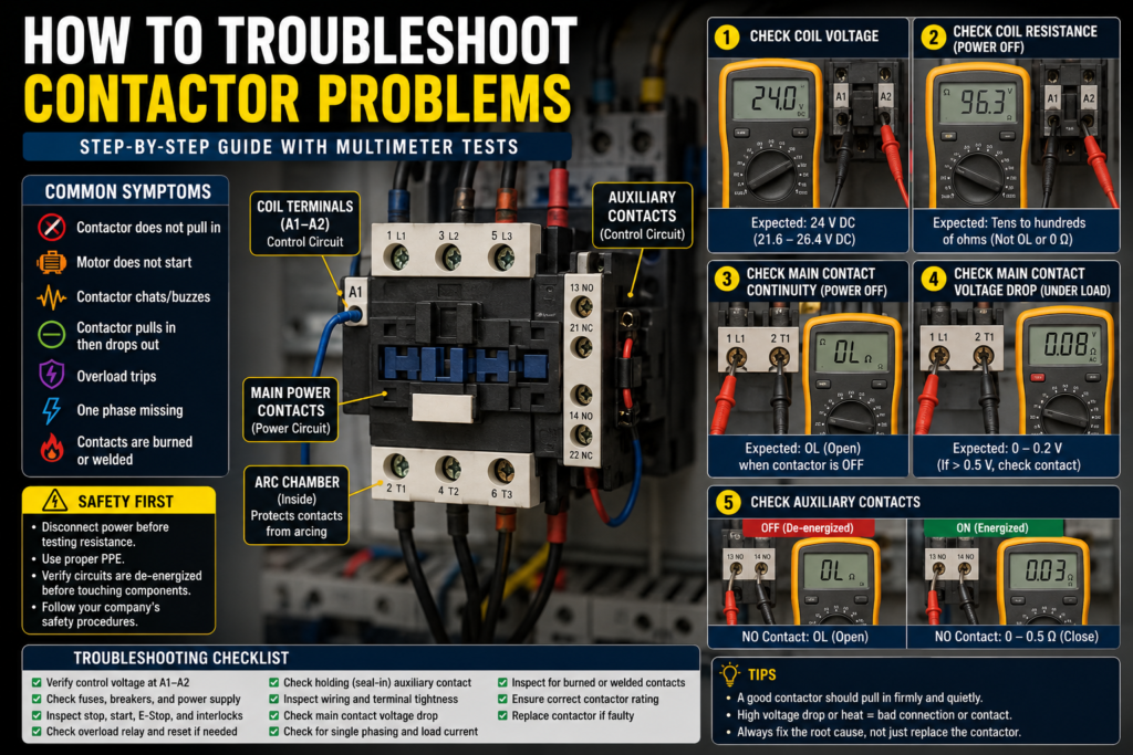
Best Multimeter Tests for Contactors
1. Coil Voltage Test
Power ON, contactor commanded ON.
Measure A1 to A2.
Expected:
24 V DC coil: around 24 V DC
230 V AC coil: around 230 V AC
120 V AC coil: around 120 V AC
If correct voltage is present but no pull-in, suspect coil or mechanical fault.
2. Coil Resistance Test
Power OFF.
Measure A1 to A2 in resistance mode.
Expected:
Not OL
Not 0 Ω
A normal resistance value depending on coil type
Compare with datasheet or known good contactor.
3. Main Contact Continuity Test
Power OFF.
Measure each main pole:
L1-T1
L2-T2
L3-T3
Contactor OFF:
All should be OL/open.
Contactor manually actuated only when safely removed from power, or energized on test bench:
All should be closed, usually 0–0.5 Ω.
4. Main Contact Voltage Drop Test
Power ON, contactor ON, load running.
Measure:
L1-T1
L2-T2
L3-T3
Expected:
0–0.1 V = very good
0.1–0.3 V = usually acceptable
Above 0.5 V = suspicious
Above 1 V = likely bad contact or connection
5. Input and Output Voltage Test
Measure three-phase voltage.
Input side:
L1-L2
L2-L3
L1-L3
Output side:
T1-T2
T2-T3
T1-T3
Expected:
Output voltage should match input voltage when contactor is ON.
If one phase is missing on output but present on input, suspect contactor pole or terminal problem.
6. Auxiliary Contact Test
Power OFF.
Measure auxiliary contacts.
NO contact:
OFF = OL
ON = 0–0.5 Ω
NC contact:
OFF = 0–0.5 Ω
ON = OL
If not changing state, replace or inspect auxiliary block.
Quick Troubleshooting by Symptom
Contactor does not pull in
Check:
Coil voltage
Fuse
Control transformer or power supply
Emergency stop
Stop button
Overload NC contact
PLC output
A1/A2 wiring
Coil resistance
Correct coil voltage
Most important test:
Measure voltage across A1 and A2.
Contactor pulls in but motor does not run
Check:
Main input voltage
Main output voltage
Main contact voltage drop
Overload relay
Motor cable
Motor terminals
Motor windings
Mechanical load
Most important test:
Compare L1/L2/L3 input with T1/T2/T3 output.
Contactor buzzes
Check:
Low coil voltage
Wrong coil type
AC/DC mismatch
Dirty core
Damaged shading ring
Loose armature
Unstable control signal
Most important test:
Measure coil voltage while buzzing.
Contactor pulls in then drops out
Check:
Holding auxiliary contact
Start/stop circuit
Overload contact
PLC output command
Voltage drop
Control supply stability
Loose terminals
Most important test:
Monitor A1-A2 voltage when it drops out.
Motor overload trips
Check:
Motor current
Overload setting
Mechanical load
Single-phasing
Bad contactor pole
Motor cable
Motor insulation
Bearing or pump jam
Too frequent starts
Most important test:
Clamp current on all three phases.
Motor runs when contactor should be off
Check:
Welded main contacts
Backfeed
Wrong wiring
Manual override
Stuck contactor
Parallel supply path
Most important test:
Power OFF, check L1-T1, L2-T2, L3-T3 continuity with contactor de-energized.
Final Thoughts
Contactor troubleshooting becomes much easier when you separate the problem into two sides:
Control circuit: coil, PLC output, push buttons, safety circuit, overload contact, A1/A2 voltage.
Power circuit: main contacts, motor supply, overload relay, terminals, motor wiring, load current.
Start with the coil.
If the coil does not receive the correct voltage, the problem is in the control circuit.
If the coil receives the correct voltage but the contactor does not pull in, suspect the coil or mechanical part of the contactor.
If the contactor pulls in but the motor does not run correctly, check the main contacts, output voltage, overload relay, motor wiring, and motor current.
The best tests are:
Coil voltage test
Coil resistance test
Main contact continuity test
Main contact voltage drop test
Input/output voltage comparison
Auxiliary contact test
Motor current balance test
Do not just replace the contactor without checking why it failed.
A burned contactor is often a symptom, not the root cause.
In industrial automation, good troubleshooting is not guessing. It is measuring, comparing, and following the circuit step by step.