Wiring a 24V DC sensor to a PLC input sounds simple.
Brown wire to positive. Blue wire to negative. Black wire to input.
Done, right?
Sometimes, yes.
But in real industrial panels, this is where many beginner mistakes happen. The sensor may power up, the LED may turn on, but the PLC input still does nothing. Or the input stays on all the time. Or the sensor works on the bench but not when connected to the machine.
Most of these problems come from one thing: not understanding how the sensor output and PLC input common work together.
In this article, we will go through how to wire a 24V DC sensor to a PLC input, how PNP and NPN wiring differs, what the common terminal does, and how to troubleshoot the signal with a multimeter.
What Is a 24V DC Sensor?
A 24V DC sensor is an industrial sensor powered by a 24 volt direct current supply.
These sensors are very common in automation because 24V DC is widely used in control panels, PLC inputs, machine sensors, and low-voltage control circuits.
Common 24V DC sensors include:
- Inductive proximity sensors
- Capacitive sensors
- Photoelectric sensors
- Magnetic cylinder sensors
- Ultrasonic sensors
- Pressure switches
- Level switches
- Flow switches
- Some temperature switches
Most basic industrial sensors send an ON/OFF signal to the PLC.
The sensor detects something, then changes its output state.
The PLC input reads that state and the program uses it for machine logic.
For example:
Sensor detects product.
PLC input turns on.
PLC program starts a conveyor, counts the product, or triggers the next step.
That is the basic idea.
Basic Three-Wire Sensor Wiring
Many 24V DC sensors use three wires.
The common wire colors are:
| Wire Color | Function |
|---|---|
| Brown | +24V DC supply |
| Blue | 0V DC supply |
| Black | Sensor output signal |
This is the most common arrangement for three-wire DC sensors.
The brown and blue wires power the sensor electronics. The black wire is the output that connects to the PLC input.
So the basic wiring looks like this:
- Brown wire → +24V DC
- Blue wire → 0V DC
- Black wire → PLC digital input
But this is only the simple part.
The PLC input common must also be connected correctly, and that depends on whether the sensor is PNP or NPN and how the PLC input module is designed.
That is where things get interesting.
PLC Digital Input Basics
A PLC digital input is designed to detect whether a voltage signal is present or not.
In a typical 24V DC PLC input system:
- Input OFF = no valid signal
- Input ON = valid 24V DC signal detected
The PLC input module converts the field voltage into a logical state for the PLC CPU.
For example:
- Input I0.0 OFF = logic 0
- Input I0.0 ON = logic 1
The PLC program then uses that input in ladder logic, function blocks, structured text, or another programming language.
A sensor does not usually control the machine directly. It only sends a signal to the PLC. The PLC program decides what to do with that signal.
What Does the PLC Input Common Do?
The input common is one of the most important terminals on a PLC input module.
The common terminal completes the electrical path for the input circuit.
A PLC input does not turn on just because a wire is connected to the input terminal. Current needs a complete path through the input circuit.
Depending on the input module, the common may need to be connected to:
- 0V DC
- +24V DC
This depends on whether the input is wired for PNP or NPN sensors.
Many beginners connect the sensor output to the PLC input and forget the common. Then the sensor works, but the PLC input never turns on.
The sensor output and PLC common must match.
No common, no proper signal.
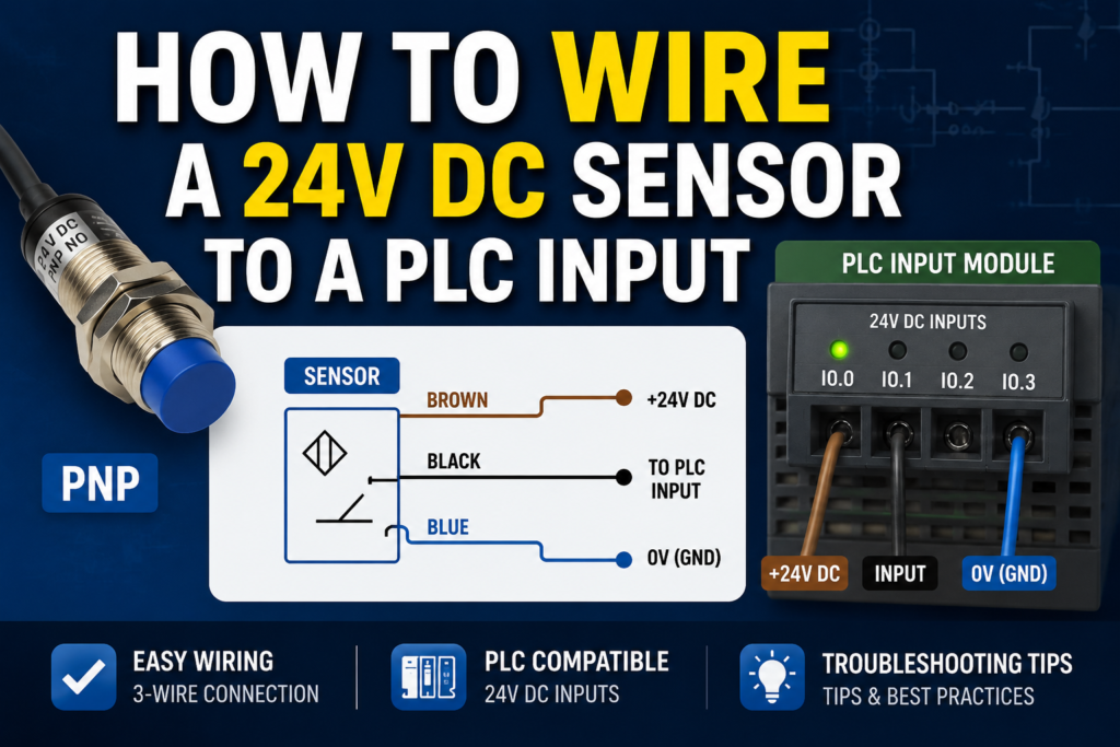
PNP Sensor Wiring to PLC Input
A PNP sensor is also called a sourcing sensor.
When the sensor turns on, it sends positive voltage to the PLC input.
In a 24V DC system, a PNP sensor output usually sends +24V DC on the black wire when active.
Typical PNP sensor wiring:
| Sensor Wire | Connection |
| Brown | +24V DC |
| Blue | 0V DC |
| Black | PLC input terminal |
| PLC input common | 0V DC |
When the sensor is inactive, the PLC input receives no positive signal.
When the sensor is active, the black output wire goes to +24V DC. Current flows into the PLC input and returns through the input common to 0V.
Basic current path:
+24V → sensor output → PLC input → PLC common → 0V
This is why the PLC input common is usually connected to 0V when using PNP sensors.
PNP Wiring Example
Imagine a PNP inductive sensor connected to PLC input I0.0.
Wiring:
- Sensor brown wire to +24V
- Sensor blue wire to 0V
- Sensor black wire to PLC input I0.0
- PLC input common to 0V
When metal is not detected:
- Sensor output is off
- I0.0 is off
- PLC input LED is off
When metal is detected:
- Sensor output sends +24V to I0.0
- PLC input turns on
- PLC input LED turns on
- PLC program sees I0.0 as true
For many 24V DC PLC systems, this is the most common wiring style.
It is also usually easier to troubleshoot because the input turns on when positive voltage appears at the input terminal.
NPN Sensor Wiring to PLC Input
An NPN sensor is also called a sinking sensor.
When the sensor turns on, it connects the PLC input to 0V.
This is different from a PNP sensor. An NPN sensor does not send positive voltage to the input. Instead, it provides a path to negative or 0V.
Typical NPN sensor wiring:
| Sensor Wire | Connection |
| Brown | +24V DC |
| Blue | 0V DC |
| Black | PLC input terminal |
| PLC input common | +24V DC |
When the sensor is active, current flows from the PLC input common through the input circuit and then through the sensor output to 0V.
Basic current path:
+24V → PLC common/input circuit → PLC input → sensor output → 0V
This is why the PLC input common is usually connected to +24V when using NPN sensors.
NPN Wiring Example
Imagine an NPN photoelectric sensor connected to PLC input I0.1.
Wiring:
- Sensor brown wire to +24V
- Sensor blue wire to 0V
- Sensor black wire to PLC input I0.1
- PLC input common to +24V
When no object is detected:
- Sensor output is off
- Input circuit is not pulled to 0V
- I0.1 is off
When an object is detected:
- Sensor output switches to 0V
- Current flows through the PLC input circuit
- I0.1 turns on
- PLC input LED turns on
- PLC program sees I0.1 as true
NPN wiring is common in some machines and regions, but it is very important to wire the input common correctly.
If you connect an NPN sensor to an input group wired for PNP, the input may not work.
PNP vs NPN Wiring Difference
The physical sensor wires may look the same, but the current path is different.
| Feature | PNP Sensor | NPN Sensor |
| Output action | Sends +24V to input | Pulls input to 0V |
| Other name | Sourcing sensor | Sinking sensor |
| PLC input common | Usually 0V | Usually +24V |
| Active signal at input | Positive voltage appears | Input is switched to 0V |
| Common in | Many European 24V DC systems | Some Asian/Japanese-style systems and older machines |
Simple memory trick:
PNP = positive signal to PLC input.
NPN = negative/0V switching to PLC input.
That is the main difference.
Two-Wire Sensor Wiring
Not all sensors are three-wire sensors.
Some sensors are two-wire devices.
A two-wire sensor is wired in series with the PLC input circuit, almost like a switch. It needs a small amount of current to power its internal electronics, so it may have leakage current even when off.
A basic two-wire DC sensor has:
- One wire to supply
- One wire to PLC input or load path
Two-wire sensors can be to supply
- One wire to PLC input or load path
Two-wire sensors can be convenient, but they can also create problems with PLC inputs because of leakage current or voltage drop.
Possible issues include:
- PLC input stays slightly energized
- Input flickers
- Input does not fully turn on
- Sensor works with one input module but not another
- Off-state leakage causes false signals
When using two-wire sensors, always check the sensor leakage current and PLC input threshold.
For beginners, three-wire sensors are usually easier to understand and troubleshoot.
Four-Wire Sensor Wiring
Some sensors have four wires.
Common colors:
| Wire Color | Common Function |
| Brown | +24V DC |
| Blue | 0V DC |
| Black | Output 1 |
| White | Output 2 or second function |
The white wire may be:
- Normally closed output
- Second switching output
- Teach-in wire
- Alarm output
- Complementary output
- Analog output on some sensors
Do not assume the white wire is always the same function.
Check the datasheet.
A four-wire sensor may provide both NO and NC outputs, or it may offer two different signal functions.
M12 Connector Sensor Wiring
Many industrial sensors use M12 connectors instead of fixed cables.
A common 4-pin M12 sensor pinout is:
| M12 Pin | Common Wire Color | Function |
| Pin 1 | Brown | +24V DC |
| Pin 3 | Blue | 0V DC |
| Pin 4 | Black | Output |
| Pin 2 | White | Second output or function |
This is very common, but it is not guaranteed for every sensor.
Always check:
- Sensor wiring diagram
- M12 cable pinout
- Connector keying
- Pin numbering
- Output function
- NO/NC setting
- PNP/NPN type
A wrong M12 cable or wrong pin assumption can make troubleshooting very confusing.
The sensor LED may turn on, but the PLC input wire may be connected to the wrong pin.
Normally Open and Normally Closed Sensor Logic
PNP and NPN describe the electrical output type.
Normally open and normally closed describe the output logic.
A normally open sensor output turns on when the sensor detects the target.
A normally closed sensor output turns off when the sensor detects the target.
For example, a PNP normally open sensor:
- No target = output off
- Target detected = output sends +24V
A PNP normally closed sensor:
- No target = output sends +24V
- Target detected = output off
So do not confuse these terms.
PNP/NPN tells how the sensor switches electrically.
NO/NC tells when the sensor switches.
Both must be correct for the application.
Step-by-Step: Wiring a PNP Sensor to a PLC Input
Here is a practical step-by-step method for wiring a common PNP sensor.
1. Check the Sensor Label
Confirm:
- Supply voltage is 24V DC
- Output type is PNP
- Output logic is NO or NC
- Maximum output current
- Wiring diagram
- Connector pinout, if used
Do not rely only on sensor shape or wire colors.
2. Turn Off Power
Before wiring, isolate the control voltage.
Do not wire sensors live unless the system is designed for it and you are trained to do so.
3. Connect Brown to +24V
Connect the brown sensor wire to the 24V DC positive supply.
4. Connect Blue to 0V
Connect the blue sensor wire to the 0V DC supply.
5. Connect Black to PLC Input
Connect the black output wire to the selected PLC input terminal, for example I0.0.
6. Connect PLC Input Common to 0V
For a typical PNP input group, connect the PLC input common terminal to 0V.
7. Power On and Test
Apply power and check:
- Sensor power LED
- Sensor switching LED
- PLC input LED
- PLC online input status
When the sensor detects the target, the PLC input should turn on.
Step-by-Step: Wiring an NPN Sensor to a PLC Input
Here is a practical method for wiring an NPN sensor.
1. Check the Sensor Label
Confirm:
- Supply voltage is 24V DC
- Output type is NPN
- Output logic is NO or NC
- Maximum output current
- Wiring diagram
2. Turn Off Power
Make the circuit safe before wiring.
3. Connect Brown to +24V
Connect the brown sensor wire to positive 24V DC.
4. Connect Blue to 0V
Connect the blue sensor wire to 0V DC.
5. Connect Black to PLC Input
Connect the black output wire to the chosen PLC input terminal.
6. Connect PLC Input Common to +24V
For a typical NPN input group, connect the PLC input common terminal to +24V.
7. Power On and Test
Activate the sensor and check:
- Sensor LED
- PLC input LED
- Online PLC input status
- Voltage at the input terminal
If the sensor LED changes but the PLC input does not, check the input common first.
Good Voltage Readings for PNP Sensor Wiring
For a 24V DC PNP normally open sensor, use a multimeter set to DC voltage.
Measure between blue wire or 0V and the other points.
| Measurement | Sensor Inactive | Sensor Active | Meaning |
| Brown to blue | Around 24V DC | Around 24V DC | Sensor has power |
| Black to blue | Around 0V | Around 24V DC | Output switches positive |
| PLC input to 0V | Around 0V | Around 24V DC | Signal reaches PLC input |
| PLC input LED | OFF | ON | PLC sees input |
Bad readings:
| Problem Reading | Possible Cause |
| Brown to blue = 0V | No sensor supply, blown fuse, broken wire |
| Black never reaches 24V | Sensor not detecting, wrong type, faulty output |
| Black always 24V | Sensor stuck on, wrong NO/NC type, short to +24V |
| Black has 24V but PLC LED off | Wrong common, bad input, loose terminal, wrong input group |
Good Voltage Readings for NPN Sensor Wiring
NPN sensor testing depends more on how the input module is wired, but the principle is that the sensor pulls the input toward 0V when active.
For a typical NPN normally open setup:
| Measurement | Sensor Inactive | Sensor Active | Meaning |
| Brown to blue | Around 24V DC | Around 24V DC | Sensor has power |
| PLC common to 0V | Around 24V DC | Around 24V DC | Common is supplied |
| Input to 0V | May be high | Pulled low, depending on module | Sensor is sinking |
| PLC input LED | OFF | ON | PLC sees input |
Because NPN inputs are less intuitive to measure, always compare the wiring with the PLC module manual.
Bad readings:
| Symptom | Possible Cause |
| Sensor LED ON but PLC input OFF | Wrong common, wrong input type, broken output wire |
| Input always ON | Short to 0V, wrong NO/NC type, wiring error |
| Input never ON | No supply, no pull-up path, wrong sensor type |
| Voltage readings confusing | Measuring against wrong reference point |
For NPN sensors, measuring only black-to-blue can mislead beginners. Understand the current path first.
PLC Input LED vs Real Voltage
PLC input LEDs are helpful, but they are not the full truth.
An input LED tells you that the module sees a valid input signal.
But it does not always prove:
- The correct input address is used in the program
- The sensor is wired to the intended terminal
- The logic is written correctly
- The input is not inverted in software
- The machine should actually respond
For example, the input LED may turn on, but the machine does nothing because the PLC program uses I0.1 while the sensor is wired to I0.2.
Or the program may require other conditions before the output turns on.
So check both:
- Physical input LED
- Online PLC input status
- Program logic
The LED is a clue, not the whole investigation.
Common Wiring Mistakes
Here are the most common mistakes when wiring 24V DC sensors to PLC inputs.
Wrong PNP/NPN Type
A PNP sensor wired to an NPN input group may not work.
An NPN sensor wired to a PNP input group may not work.
Always match sensor type and PLC input wiring.
Missing Input Common
The sensor output is connected to the PLC input, but the input common is not connected.
Result: PLC input never turns on.
Wrong Common Polarity
PNP sensors usually need input common to 0V.
NPN sensors usually need input common to +24V.
Wrong common = no signal.
No Shared 0V Reference
If the sensor power supply and PLC input circuit do not share the correct reference, the signal may not work.
Always check the 0V and common connections.
Wrong Input Address
The wiring is correct, but the PLC program uses the wrong input address.
Always compare the electrical drawing, terminal number, and PLC software.
Sensor Output Overloaded
A sensor output can only switch a limited current.
Do not use a small sensor output to directly energize a large load unless it is rated for it.
Usually, the sensor output should go to a PLC input, not directly to a contactor coil.
Broken Cable or Connector
Sensor cables move, bend, get crushed, or fail near connectors.
If the sensor works when moved, suspect cable damage.
NO/NC Logic Wrong
The input works, but it behaves opposite of expected.
The sensor may be normally closed instead of normally open, or the PLC program may use inverted logic.
Troubleshooting: Sensor Has Power but PLC Input Does Not Turn On
This is one of the most common faults.
Follow this checklist:
- Check sensor supply voltage between brown and blue.
- Confirm sensor LED changes when detecting the target.
- Measure sensor output voltage.
- Confirm sensor type: PNP or NPN.
- Check PLC input common wiring.
- Measure voltage directly at the PLC input terminal.
- Check PLC input LED.
- Check online PLC input status.
- Confirm input address in the program.
- Check for loose terminal or broken wire.
Do not replace parts randomly.
Follow the signal from the sensor to the PLC.
Troubleshooting: PLC Input Always ON
If the PLC input is always on, check:
- Sensor may be normally closed
- Output wire may be shorted
- Sensor may be stuck active
- Wrong sensor type may be installed
- Input may be forced on in PLC software
- Leakage current from two-wire sensor may be enough to trigger input
- Wrong common wiring may be backfeeding the input
A good test is to safely disconnect the sensor output wire from the PLC input.
If the input turns off, the issue is likely in the sensor or field wiring.
If the input stays on, check the PLC module, program forcing, or panel wiring.
Troubleshooting: PLC Input Flickers
A flickering input can be caused by:
- Loose terminal
- Damaged cable
- Sensor at edge of detection range
- Vibration
- Wrong sensing distance
- Electrical noise
- Weak power supply
- Bad 0V reference
- Incorrect sensor type
- Fast signal not handled correctly
- Two-wire sensor leakage or unstable load
For sensors installed near motors, drives, contactors, or long cables, electrical noise can become a real problem.
Use proper cable routing, shielding, grounding, and input filtering where needed.
Wiring Sensors to Input Groups
Many PLC input modules divide inputs into groups.
For example, inputs I0.0 to I0.7 may share one common terminal.
This means all sensors in that group must usually use the same wiring style.
If the group common is wired to 0V for PNP sensors, then all inputs in that group are normally used with PNP signals.
If the group common is wired to +24V for NPN sensors, then the group is used with NPN signals.
Some modules have individually isolated inputs. Others have shared commons.
Always check the module diagram before mixing different sensor types.
This is especially important when replacing or adding sensors to an existing panel.
Can a Sensor Be Connected Directly to a Relay Coil?
Sometimes a sensor output is used to control a relay coil directly.
This can work only if the sensor output is rated for the relay coil current and the wiring is protected correctly.
However, in PLC systems, it is usually better to connect the sensor to a PLC input and let the PLC program control the output.
Reasons:
- Easier diagnostics
- Better logic control
- Easier modification
- Sensor signal visible in PLC
- Better fault handling
- Less load on sensor output
If a relay coil is controlled by a sensor output, use flyback protection for DC coils or suppression for inductive loads where required.
Inductive loads can damage sensor outputs if not handled correctly.
Safety Inputs Are Different
Do not treat safety devices like ordinary sensors.
Emergency stops, safety door switches, light curtains, and safety interlocks may require safety relays, safety PLCs, dual-channel wiring, monitored contacts, and specific safety standards.
A normal PLC digital input is not automatically a safety input.
For example, wiring an emergency stop only to a standard PLC input is usually not acceptable for machine safety.
This article is about normal automation sensors and standard PLC input wiring.
Safety circuits must be designed according to proper safety requirements.
Practical Example: Inductive Sensor to PLC Input
Let’s say we have a 24V DC PNP inductive sensor detecting a metal part.
Goal:
When the metal part is present, PLC input I0.3 should turn ON.
Wiring:
- Brown wire to +24V
- Blue wire to 0V
- Black wire to I0.3
- Input group common to 0V
Test:
- No metal part: sensor LED off, I0.3 off
- Metal part present: sensor LED on, I0.3 on
- Online PLC monitor shows I0.3 = TRUE
Program example:
If I0.3 is true, the PLC knows the part is present.
The PLC can then start the next step, count the part, or allow a cylinder to move.
Practical Example: Photoelectric Sensor to PLC Input
A photoelectric sensor detects boxes on a conveyor.
Goal:
When a box is detected, PLC input I1.0 should turn ON.
For a PNP sensor:
- Brown to +24V
- Blue to 0V
- Black to I1.0
- Input common to 0V
When the box blocks or reflects the beam, depending on sensor type, the output changes state.
Check:
- Sensor alignment
- Light-on or dark-on setting
- PLC input LED
- PLC online input status
Photoelectric sensors can have additional settings, so output logic must be confirmed during commissioning.
Practical Field Checklist
Before wiring a sensor, check:
- Sensor supply voltage
- PNP or NPN output
- NO or NC logic
- Three-wire, two-wire, or four-wire type
- PLC input module type
- Input common terminals
- Input group arrangement
- Sensor cable colors
- M12 connector pinout
- Electrical drawing
- PLC input address
After wiring, test:
- 24V supply at sensor
- Sensor LED operation
- Output voltage change
- Voltage at PLC input terminal
- PLC input LED
- Online PLC input status
- Correct PLC program response
This checklist catches most wiring problems before they become bigger faults.
Final Thoughts
Wiring a 24V DC sensor to a PLC input is simple only when the sensor type, PLC input type, and common wiring all match.
For a typical three-wire sensor, brown goes to +24V, blue goes to 0V, and black goes to the PLC input. But the input common is just as important.
For PNP sensors, the output sends positive voltage to the PLC input, and the input common is usually connected to 0V.
For NPN sensors, the output switches the input to 0V, and the input common is usually connected to +24V.
If the sensor LED turns on but the PLC input does not, check the sensor output type, common terminal, voltage at the input, and PLC address before replacing parts.
The key idea is current path.
Once you understand where the current comes from and where it returns, PLC sensor wiring becomes much easier.
Brown to +24V.
Blue to 0V.
Black to the input.
Then make the common match the sensor.
That is the foundation of wiring 24V DC sensors to PLC inputs.