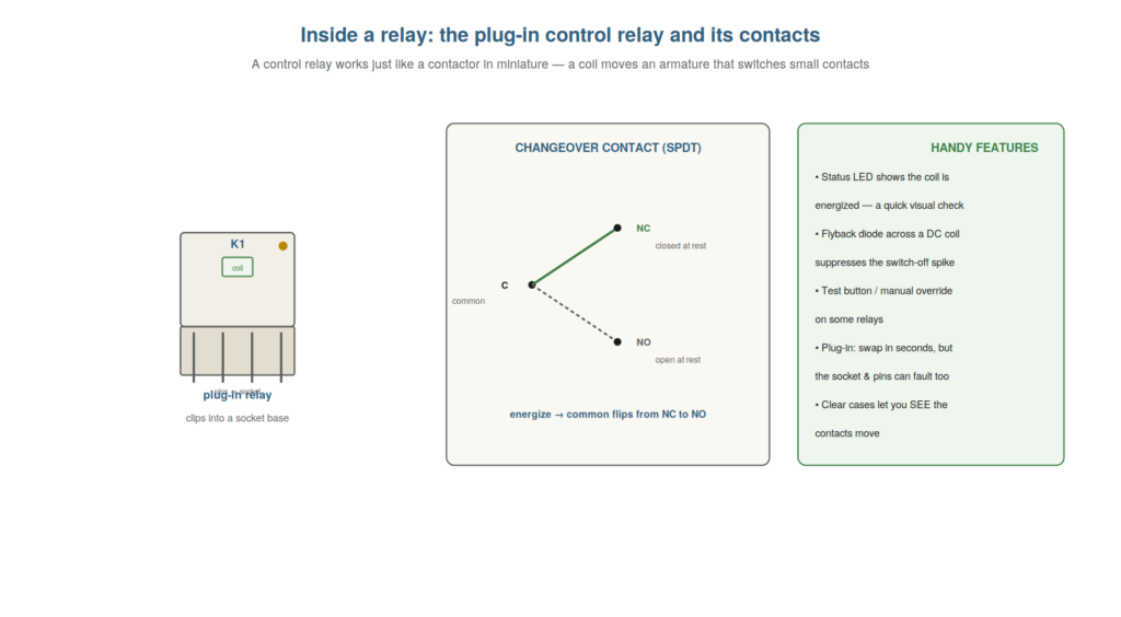
A control relay works on exactly the same principle as a contactor — a coil moving contacts — but its smaller scale and features (plug-in construction, changeover contacts, a status LED) give it its own character and faults, and understanding them helps you troubleshoot relays specifically. Where a contactor’s faults center on its heavy contacts and mechanism, a relay’s often involve its socket, its pins, its small contacts, and its coil. This chapter opens up the control relay, so you understand the device and its particular quirks.
The plug-in relay and its socket
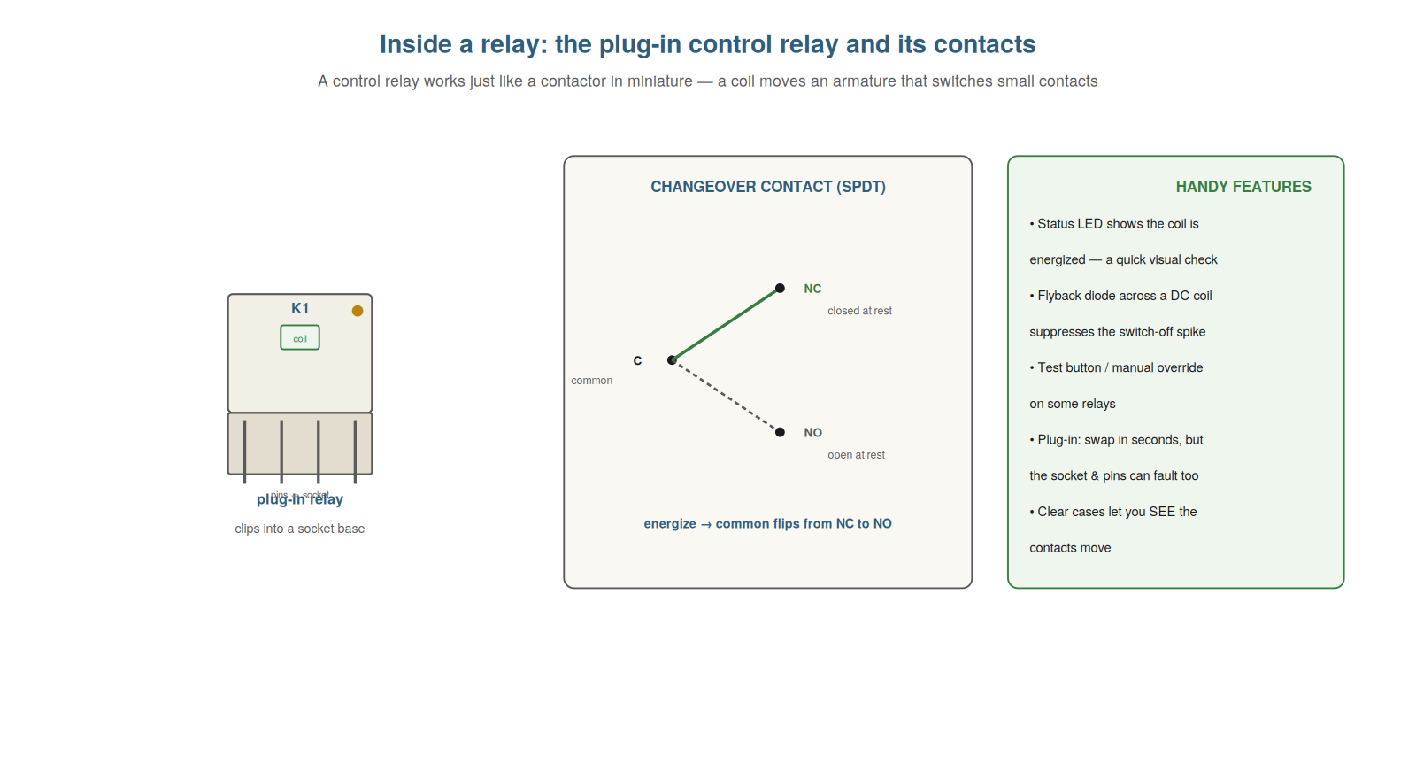
A defining feature of many control relays is plug-in construction, and understanding the relay-and-socket arrangement is important because the socket and pins are themselves a source of faults. A plug-in relay has pins that plug into a socket (base) wired into the circuit, so the relay can be removed and replaced in seconds without rewiring — a great convenience for maintenance. But this arrangement introduces its own fault points: the pins can corrode or spread, the relay can be not fully seated, and the socket contacts can lose tension or corrode, any of which makes an unreliable connection between the relay and the circuit. So the plug-in relay is convenient but adds the socket-and-pin interface as a potential fault. Understanding this has a practical payoff: when a plug-in relay misbehaves, re-seating it or swapping it (and checking the socket and pins) is a quick, often decisive step — the fault may be the connection, not the relay itself. So understanding the plug-in relay and its socket — convenient replacement but an extra connection to fault — directs a quick and useful troubleshooting step. Understanding the plug-in relay and its socket — the pins plugging into a wired base for quick replacement, but introducing the socket and pins as a fault point where corrosion, spread pins, poor seating, or lost socket tension make unreliable connections — is important because it directs a quick and useful troubleshooting step, so that when a plug-in relay misbehaves you re-seat or swap it and check the socket and pins, recognizing that the fault may lie in the connection rather than the relay, which is one of the fastest and most decisive checks for the plug-in relays common in control panels.
Changeover contacts
Many relays have changeover contacts, and understanding this arrangement clarifies how to read and test a relay’s contacts. A changeover (SPDT) contact has three terminals: a common (C), a normally-closed (NC), and a normally-open (NO). At rest, the common connects to the NC; when the coil is energized, the common flips over to connect to the NO instead. So a single changeover contact provides both a normally-closed and a normally-open path from the common, switching between them as the relay operates. Understanding this clarifies the relay’s behavior: energizing the relay moves the common from NC to NO, so a circuit on the NC path opens and one on the NO path closes, simultaneously. For troubleshooting, it tells you what to expect: with the relay de-energized, common-to-NC should have continuity and common-to-NO should not; energized, the reverse. Testing against this reveals a faulty contact. So understanding changeover contacts — the common flipping between NC and NO — clarifies reading and testing a relay’s contacts. Understanding changeover contacts — the common that connects to the NC at rest and flips to the NO when energized, providing both paths from one common — clarifies how to read and test a relay’s contacts, so that you know what to expect at each state (common-to-NC closed and common-to-NO open when de-energized, and the reverse when energized) and can test the relay’s contacts against this, revealing a faulty contact when the measured behavior does not match, which is the key to diagnosing the changeover contacts that many control relays provide.
Status LEDs, diodes, and seeing the state
Relays often have helpful features — a status LED, a flyback diode, sometimes a clear case — and understanding them gives you quick ways to check a relay’s state and explains some of its behavior. A status LED, common on control relays, lights when the coil is energized, giving an instant visual check: is the relay’s coil energized right now? A flyback (freewheeling) diode is often fitted across a DC relay coil to suppress the voltage spike when the coil de-energizes, protecting other components — understanding it explains its presence and that a failed diode can affect the coil circuit. A clear case, on many relays, lets you actually see the armature and contacts move, confirming visually whether the relay is operating. Understanding these features gives you quick checks: the LED tells you the coil state at a glance, and a clear case lets you watch the operation, both faster than measuring. So understanding status LEDs, diodes, and clear cases — the features that show a relay’s state — gives you quick visual checks and explains the relay’s construction. Understanding status LEDs, diodes, and seeing the state — the LED that lights when the coil is energized, the flyback diode that suppresses the switch-off spike on a DC coil, and the clear case that lets you watch the contacts move — gives you quick ways to check a relay’s state and explains its construction, so that you use the LED for an instant read of whether the coil is energized, watch a clear-cased relay actually operate, and recognize the flyback diode as a normal feature (whose failure can affect the coil circuit), which provides fast visual checks of a relay’s operation that often shortcut the need to measure.
Relay types: ice-cube, DIN, PCB, and interface
A useful breadth of understanding is the different relay types you meet, because knowing the common forms helps you recognize and handle each. The ‘ice-cube’ relay (a small clear-cased plug-in relay) is the classic general-purpose control relay, plugging into a socket. Slimline interface relays are narrow modules on the DIN rail, often used to interface PLC outputs to field devices — a low-power PLC output drives the relay’s coil, and the relay’s contact switches the actual load. Some relays are mounted directly on printed circuit boards (PCB relays) inside equipment. Timer relays add a time delay. Understanding these types helps you recognize what you are dealing with and how to handle it: an ice-cube relay is swapped by unplugging, an interface relay isolates and boosts a PLC output, and so on. So understanding relay types — ice-cube, slimline interface, PCB, timer — helps you recognize and handle the common forms. Understanding the different relay types — the plug-in ice-cube relay, the slimline interface relay bridging PLC outputs to field loads, PCB-mounted relays, and timer relays — helps you recognize and handle each form, so that you know an ice-cube relay is swapped by unplugging, an interface relay isolates and boosts a low-power PLC output to switch a real load, and the various forms serve their purposes, which orients you to the range of relays in a control panel and how each is handled when it comes to troubleshooting or replacement.
Scenario: the relay that wasn’t the problem
A scenario shows how understanding the plug-in relay and socket saves a misdiagnosis. A control relay was behaving intermittently, and the instinct was to replace it — but the technician, understanding that the socket and pins are themselves fault points, checked those first. He unplugged the relay and inspected: the socket contacts had lost some tension and one pin showed corrosion, making an unreliable connection. So the fault was the socket-and-pin interface, not the relay. He cleaned the pins, re-tensioned the socket (or replaced the socket), and re-seated the relay — and the intermittent fault cleared, with the original relay working fine. Understanding that a plug-in relay’s connection is a fault point saved him from replacing a good relay and leaving the real fault (the socket) unaddressed. This scenario shows how understanding the plug-in relay and socket prevents a misdiagnosis. Understanding that the socket and pins are fault points led the technician to check them before blaming the relay. It reinforces that a plug-in relay’s socket and pins are common faults, so checking them can save replacing a good relay. The scenario reinforces understanding the relay’s construction: knowing the plug-in relay’s socket and pins are themselves fault points led the technician to find a corroded pin and slack socket rather than needlessly replacing a good relay, illustrating how understanding the relay-and-socket interface directs you to check the connection before condemning the relay, and correctly resolves the fault at the socket where it actually lay.
Relay contact materials and load types
A useful nuance is that relay contacts come in different materials for different loads, because using the wrong type causes reliability problems. Relay contacts are made of various materials (silver alloys, gold-plated, and others) suited to different loads: gold-plated or low-power contacts suit tiny signal-level currents (they resist the oxidation that would prevent a small current making through a film), while silver-alloy contacts suit higher currents but may not reliably switch very small ones (an oxide film can build up that a small current cannot break through). So a relay switching a tiny signal needs contacts suited to it, and one switching a larger load needs different contacts. Understanding this explains a reliability problem: a relay with the wrong contact type for its load — for instance, silver contacts asked to switch a very small signal current — may make unreliably as an oxide film builds up. So matching the relay’s contact type to the load matters. Understanding relay contact materials and load types explains this class of reliability issue. So understanding relay contact materials and load types explains reliability problems from a mismatch. Understanding that relay contacts come in different materials for different loads — gold-plated or low-power contacts for tiny signal currents that resist oxidation, versus silver-alloy contacts for higher currents that may not reliably switch very small ones — explains reliability problems from a mismatch, so that you understand a relay switching a tiny signal needs contacts suited to it (or an oxide film may prevent the small current making), which explains the unreliable operation of a relay whose contact type does not match its load and directs you to select a relay whose contacts suit the current it switches.
The relay’s quirks as troubleshooting shortcuts
To close, it helps to see the relay’s particular features as troubleshooting shortcuts, because each feature offers a fast check. The status LED is a shortcut to the coil state (lit means energized) — no measurement needed. The clear case is a shortcut to seeing the contacts operate. The plug-in construction is a shortcut to a fix or a test (re-seat or swap in seconds). Understanding these features as shortcuts means you use them first: glance at the LED, watch through the case, re-seat or swap the relay — fast checks that often resolve or localize the fault before you reach for a meter. So the relay’s quirks are not just construction details but practical shortcuts. Understanding them as shortcuts makes relay troubleshooting fast. So seeing the relay’s quirks as troubleshooting shortcuts speeds relay diagnosis. Understanding the relay’s particular features as troubleshooting shortcuts — the status LED for the coil state, the clear case for seeing the contacts, and the plug-in construction for a fast re-seat or swap — speeds relay diagnosis, so that you use these features first (glancing at the LED, watching through the case, re-seating or swapping the relay) as fast checks that often resolve or localize the fault before measuring, which turns the relay’s quirks from mere construction details into practical shortcuts that make relay troubleshooting quick and effective.