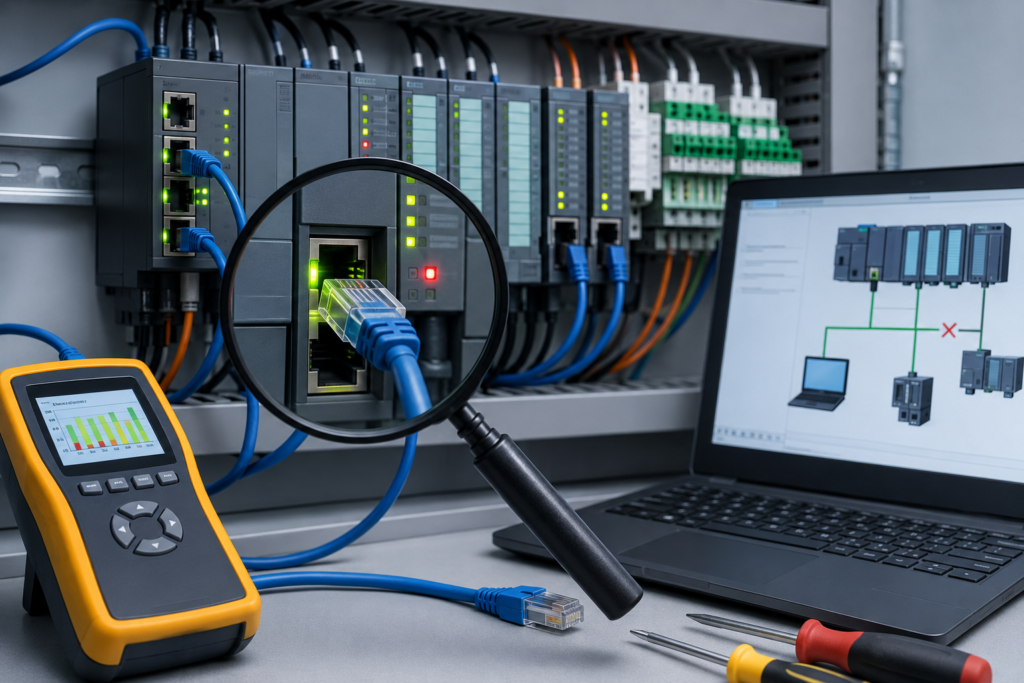
A network that fails completely is almost polite.
The fault stays present. The red LED remains red. The PLC cannot see the remote I/O, and every test produces the same result. You can work through the system, isolate the broken section and eventually find the culprit.
Intermittent communication faults are different.
The HMI displays Communication Lost for three seconds, then recovers before anyone reaches the cabinet. A remote I/O station disappears once per shift. A drive reports a network timeout only when production is running at full speed. Maintenance connects a laptop, watches the network for an hour and sees absolutely nothing wrong.
Then they walk away.
Five minutes later, the machine stops again.
These problems test patience because the network is often healthy while it is being inspected. The fault may depend on vibration, temperature, electrical load, cable position or a timing conflict that occurs only under very specific conditions.
Random replacement sometimes works, but it is expensive and teaches you very little. A better approach is to collect evidence, search for patterns and eliminate possible causes one layer at a time.
What Is an Intermittent Communication Fault?
An intermittent communication fault is a temporary loss or corruption of data between industrial devices.
The connection may fail for:
- A few milliseconds
- Several seconds
- A few minutes
- One event per shift
- One event every few weeks
Communication then returns without anyone repairing anything.
The affected system may use:
- PROFINET
- EtherNet/IP
- Modbus TCP
- Modbus RTU
- PROFIBUS
- DeviceNet
- CANopen
- EtherCAT
- Serial communication
- A manufacturer-specific fieldbus
The protocol changes some details, but many causes remain the same:
- Loose connections
- Damaged cables
- Unstable power
- Electrical interference
- Incorrect termination
- Duplicate addresses
- Failing switch ports
- Environmental conditions
- Excessive network traffic
- Marginal hardware
The word intermittent does not mean the fault has no cause.
It means the cause only becomes active under certain conditions.
Typical Symptoms of Intermittent Communication Problems
Intermittent faults do not always announce themselves as obvious network failures.
Sometimes the machine symptom appears unrelated to communication.
HMI communication alarms
The HMI may briefly display:
- PLC connection lost
- Device unavailable
- Communication timeout
- Data source disconnected
- Tag quality bad
The alarm may disappear automatically once communication returns.
Remote I/O drops out
A PLC temporarily loses contact with an I/O adapter.
Depending on the configuration, outputs may:
- Turn off
- Hold their last state
- Move to configured fallback values
- Trigger a controller fault
- Stop part of the machine
The I/O station may reconnect before anyone sees its fault LEDs.
Drives report fieldbus faults
A VFD or servo drive may show:
- Network timeout
- Fieldbus loss
- Telegram failure
- Bus-off condition
- Communication watchdog fault
The drive may stop even though the network interruption lasted only a fraction of a second.
Fault codes appear and clear themselves
The PLC diagnostic buffer fills with communication warnings, but the devices are online by the time maintenance investigates.
This often produces comments such as:
“It must have been a random glitch.”
Maybe. Usually not.
Status LEDs flicker between states
A network LED that should remain solid green may:
- Flash red briefly
- Alternate red and green
- Turn off for a moment
- Restart through its normal boot sequence
A phone video of the LEDs during the failure can sometimes reveal more than staring at them afterward.
The machine stops without an obvious reason
Operators may report:
- “It resets itself sometimes.”
- “That station freezes for a second.”
- “The conveyor stops, then starts again.”
- “It only happens on the afternoon shift.”
- “The machine hates hot days.”
These reports sound vague, but they often contain useful timing information.
Data values freeze or jump
An HMI value may stop updating, then suddenly jump to the newest value.
A PLC may retain stale data while a communication connection is lost.
In other cases, corrupted or incomplete communication produces impossible values, alarms or unexpected program behaviour.
Why Intermittent Faults Are So Difficult to Find
A solid failure gives you a stable condition to measure.
An intermittent failure may vanish before:
- The technician arrives
- The programming software connects
- The cabinet door is opened
- A multimeter is placed on the circuit
- A network capture begins
Opening the cabinet may even cool the equipment or move a loose cable enough to restore the connection.
The fault can also be too brief for normal observation. PLC programming software usually refreshes much more slowly than the controller executes. A network bit may drop for 20 milliseconds and return before it is visibly highlighted.
That is why troubleshooting intermittent communication requires recording tools and event history—not only live observation.
Start by Defining the Scope
Before changing anything, determine how much of the network is affected.
Ask:
- Is one device dropping offline?
- Is one group of devices affected?
- Does an entire remote I/O rack disappear?
- Does every device behind one switch fail?
- Does the PLC itself restart?
- Does the HMI lose the PLC while the PLC still communicates with I/O?
- Are all machines on the same network affected?
- Does the fault follow one product, shift or machine movement?
The scope immediately narrows the likely causes.
One device fails
Suspect:
- Local power
- Local connector
- Drop cable
- Device configuration
- Device hardware
- One switch port
Several devices fail together
Look for something they share:
- Ethernet switch
- Network trunk
- Power supply
- Remote I/O adapter
- Fibre link
- Cabinet temperature
- Communication module
The entire network fails
Investigate:
- PLC communication interface
- Main switch
- Network power
- Ring or backbone failure
- Broadcast storm
- Controller restart
- Router or VLAN problem
Do not begin by replacing a field device when fifteen devices disappear simultaneously.
Record the Exact Time of Every Failure
Time is one of the most important clues.
Record:
- Date
- Exact time
- Duration
- Devices affected
- Machine operating state
- Active recipe
- Motors or heaters running
- Environmental conditions
- Fault codes
- Whether communication recovered automatically
Synchronize clocks where possible.
If the PLC, HMI, managed switch and drive all use different times, comparing their logs becomes unnecessarily painful.
Accurate timestamps allow you to line up events:
- 14:22:18 — Large compressor starts
- 14:22:19 — 24 V supply dips
- 14:22:19 — Ethernet adapter disconnects
- 14:22:20 — Remote I/O fault appears
- 14:22:21 — Machine sequence stops
That sequence tells a much clearer story than “I/O communication fault around lunchtime.”
Look for Patterns
Intermittent does not necessarily mean random.
Ask whether the failure occurs:
- At the same time every day
- When a certain motor starts
- During welding
- When a robot reaches one position
- When a cable chain extends
- After the cabinet warms up
- During cold mornings
- After heavy rain
- Only at full production speed
- When a replacement device is powered
- During backups or network scans
- After an air conditioner switches off
A pattern may not identify the exact failed component, but it points toward a category.
Failure during movement
Suspect a flexing cable, connector or terminal.
Failure when a large load starts
Suspect voltage drop, grounding or electromagnetic interference.
Failure after hours of operation
Suspect heat, power-supply drift or a component beginning to fail.
Failure during one shift
Check which equipment, production recipe or maintenance activity is unique to that shift.
Failure after rain or washdown
Inspect for moisture inside connectors, junction boxes and cable entries.
Loose Connections: The Usual Suspect
Loose connections are among the most common causes of intermittent communication faults.
Possible locations include:
- RJ45 connectors
- M12 connectors
- Terminal blocks
- PROFIBUS plugs
- DeviceNet taps
- Serial communication terminals
- Shield clamps
- Switch power terminals
- Remote I/O power connectors
- Fibre couplers
A connection may work while stationary but open briefly when exposed to vibration.
Temperature changes also matter. Metal expands and contracts. A marginal terminal may make good contact while cold and become unreliable after the cabinet heats up.
Corrosion can create similar behaviour. The connection may pass enough current or signal most of the time, then fail when vibration or humidity changes its resistance.
Inspect connections physically.
Do not simply look from a distance and decide they seem fine.
Where permitted and safe:
- Check terminal torque
- Reseat connectors
- Inspect pins
- Look for discoloration
- Check for moisture
- Examine shield contact
- Replace damaged locking clips
Be careful with repeated tightening. Overtightening can damage terminals just as effectively as leaving them loose.
Use manufacturer torque values where available.
Damaged Communication Cables
Industrial environments are not kind to cables.
They are:
- Crushed by cabinet doors
- Pinched under machine frames
- Pulled tight during modifications
- Bent beyond their minimum radius
- Exposed to oil and coolant
- Run through hot areas
- Dragged through cable chains
- Struck by forklifts
- Nicked by sharp metal edges
A cable can be mostly damaged and still communicate most of the time.
One conductor may be broken internally but continue touching until the cable moves. Shield continuity may be poor. An RJ45 plug may have one weak crimp. A cable designed for fixed installation may have been used in continuous motion.
Pay special attention to:
- Moving axes
- Robot dress packs
- Cable chains
- Hinged doors
- Vibrating equipment
- Recently modified areas
- Temporary cable joints
- Field-installed connectors
A standard continuity check may not find every problem.
Flex the cable gently during testing, where safe. Better still, substitute a known working cable and monitor the result.
Incorrect Cable Type
Not all cables with familiar connectors are suitable for industrial communication.
A normal office Ethernet patch cable may work inside a cabinet, but it may not survive:
- Continuous flexing
- Oil exposure
- High temperatures
- Strong electromagnetic fields
- Mechanical abrasion
Likewise, ordinary two-core cable is not a proper replacement for a specified RS-485 or PROFIBUS cable.
The protocol may require controlled:
- Impedance
- Capacitance
- Shielding
- Twisting
- Conductor size
- Propagation characteristics
A system can appear to work with the wrong cable and then fail under high traffic, long distance or noisy conditions.
That is the dangerous part. The installation looks successful—until it is not.
Check Network Termination
Serial and fieldbus networks often require termination at the physical ends of the bus.
Protocols that may use termination include:
- PROFIBUS
- DeviceNet
- Modbus RTU over RS-485
- CAN-based networks
Problems occur when:
- A terminating resistor is missing
- Too many terminators are installed
- The wrong resistor value is used
- An intermediate device is terminated
- A powered terminator loses power
- The final device is replaced and its termination switch is left off
Incorrect termination can produce signal reflections.
The network may still operate under light traffic or quiet electrical conditions, then fail when timing, noise or cable length becomes less forgiving.
Check the actual physical ends of the network.
Do not assume the first and last devices in the PLC project are the physical cable ends.
Marginal Power Supplies
Communication devices need stable power.
A network adapter supplied with “about 24 volts” most of the time can still disconnect if the voltage dips during load changes.
Common causes include:
- Undersized power supply
- Ageing power supply
- Loose power terminal
- Excessive cable voltage drop
- Shared solenoid loads
- Failing DC UPS
- Bad fuse holder
- Short-duration overload
- High ripple
- Poor grounding
Measure voltage at the affected device, not only at the power-supply output.
The fault may occur when:
- Several valves energize
- A contactor closes
- A brake releases
- A large DC load starts
- A cabinet heater switches
- A remote station reaches peak load
An ordinary multimeter may miss a short voltage dip.
For brief disturbances, use:
- Min/max recording
- Data logger
- Power-quality recorder
- Oscilloscope
- PLC analog logging, where suitable
If a communication adapter’s LEDs restart from their power-up sequence, do not spend three hours analysing packets before checking its supply.
Electrical Noise and Electromagnetic Interference
Industrial communication cables often share space with noisy equipment.
Common interference sources include:
- VFD output cables
- Servo drives
- Large contactors
- Welding equipment
- Induction heaters
- Braking resistors
- High-current switching
- Poorly suppressed coils
- Inadequately grounded machinery
Noise may not completely destroy communication.
It may corrupt only an occasional packet, causing:
- Retries
- CRC errors
- Timeout alarms
- Brief device disconnects
- Increased network error counters
That is why the system may run normally for hours before failing.
Check Cable Routing
Communication and power wiring should be separated according to manufacturer guidance and applicable installation practices.
Avoid running communication cable parallel to:
- Motor cables
- VFD output wiring
- High-current conductors
- Contactor output wiring
Where crossings are unavoidable, crossing close to 90 degrees is generally better than running the cables side by side.
Temporary separation can be a useful diagnostic test.
Move a known working temporary communication cable away from the power wiring. If the problem disappears, cable routing or shielding becomes a strong suspect.
Do not leave the test cable hanging across a walkway as the permanent solution.
Shielding and Grounding
Shielding problems can create intermittent communication errors, particularly in electrically noisy environments.
Check:
- Shield continuity
- Correct shield clamps
- Low-impedance bonding
- Cabinet grounding
- Equipotential bonding between machines
- Manufacturer grounding instructions
- Connector shield contact
A shield twisted into a long thin pigtail has much higher impedance at high frequencies than a proper 360-degree clamp.
Grounding practices depend on the protocol and installation. Do not blindly disconnect shields or protective earth conductors to make the network appear stable.
That may hide one issue while creating a safety hazard or another communication problem elsewhere.
Duplicate IP Addresses and Node Conflicts
Every network device must have a unique address.
Duplicate addresses can create strange, timing-dependent behaviour.
On Ethernet, two devices may share the same IP address. One responds for a while, then the network’s address table updates and traffic begins reaching the other.
Symptoms can include:
- PLC appears and disappears
- HMI connects to the wrong device
- Ping replies are inconsistent
- Communication works until another device powers up
- MAC address associated with an IP keeps changing
On serial or fieldbus networks, duplicate node addresses may produce:
- Colliding responses
- Scanner errors
- Corrupted frames
- One device hiding another
- Unstable communication
A common trigger is equipment replacement.
The new device is installed with its factory-default address, and nobody checks whether that address is already in use.
For Ethernet systems, disconnect the suspected device and ping its IP address.
If another device continues replying, you have found a conflict—or at least a very interesting clue.
Network Switch Problems
Ethernet switches can fail intermittently.
Possible causes include:
- Failing switch power supply
- Damaged port
- Overheating
- Loose power connector
- Firmware problem
- Excessive packet errors
- Fibre transceiver fault
- Ring redundancy issue
- Broadcast storm
Try moving the affected cable to another switch port.
If the fault follows the port, inspect the switch.
If the fault follows the cable or device, continue downstream.
Managed switches provide valuable diagnostic data:
- Port up/down history
- CRC errors
- Dropped packets
- Link speed changes
- Duplex status
- Broadcast rates
- MAC address movement
- Ring events
- Fibre signal information
Do not reset the switch before exporting or recording its logs.
The switch may contain the only timestamped evidence of the actual fault.
Speed and Duplex Mismatches
Most modern Ethernet devices negotiate speed and duplex automatically.
Older equipment may not always negotiate correctly.
A duplex mismatch can leave the link apparently active while causing:
- Poor performance
- Packet collisions
- Retransmissions
- Timeouts under load
- Slow downloads
- Intermittent HMI freezes
Where possible, use compatible auto-negotiation settings at both ends.
If a fixed configuration is required, make sure both devices match.
One side forced to full duplex while the other assumes half duplex is an excellent recipe for a network that works badly but not badly enough to make the cause obvious.
Excessive Network Traffic
A network can also fail because it is overloaded.
Possible causes include:
- Broadcast storm
- Misconfigured multicast traffic
- Excessive HMI polling
- Too many connected clients
- Fast diagnostic queries
- Looped Ethernet cables
- Incorrect managed-switch configuration
- Device repeatedly reconnecting
- Network scanning software
- Poorly configured produced/consumed data
Symptoms may appear only during high production activity or when engineering laptops connect.
Check:
- Port utilization
- Broadcast rate
- Packet-drop counters
- PLC connection limits
- HMI update rates
- Requested packet intervals
- Number of active clients
A network loop can create severe traffic very quickly unless loop-prevention or ring protocols are configured correctly.
Never connect two switch ports together “temporarily” unless you understand the network topology.
Communication Timing Problems
Not every timeout is caused by bad wiring.
A device may respond too slowly for the configured timeout.
This is common with:
- Serial gateways
- Modbus RTU devices
- Older HMIs
- Overloaded PLC communication tasks
- Slow instruments
- Wireless links
- Networks with excessive polling
The system may work while lightly loaded and fail when more requests are added.
Review:
- Polling interval
- Response timeout
- Retry count
- Message instruction frequency
- Number of registers requested
- Connection watchdog
- PLC task execution time
Increasing a timeout can reduce nuisance faults, but it can also hide a struggling network.
Find out why the response is late.
Temperature-Related Failures
Electronic components behave differently as they heat and cool.
Possible temperature-related causes include:
- Failing switch power supply
- Marginal solder joint
- Expanding connector
- Overheated communication module
- Cabinet fan failure
- Blocked air filter
- Direct sunlight
- Condensation during cooling
A system that fails every afternoon may not be haunted.
The cabinet may simply be reaching 45°C after several hours of operation.
Measure temperature inside the cabinet and near affected devices. Compare it with the fault times.
Thermal cameras can help identify overheating equipment, though they will not reveal every internal failure.
Moisture, Contamination and Corrosion
Moisture can create intermittent resistance and leakage paths.
Inspect:
- Junction boxes
- Outdoor connectors
- Cable glands
- Washdown areas
- Underground conduits
- Cooling-system areas
- Condensation-prone cabinets
Look for:
- Green or white corrosion
- Water marks
- Oil inside connectors
- Damaged seals
- Loose cable glands
- Rusted terminals
A connector may work when dry and fail after a washdown.
This is exactly the sort of pattern operators may notice before maintenance does.
A Structured Troubleshooting Process
Intermittent problems need a more disciplined approach than permanent faults.
Step 1: Preserve the Evidence
Before resetting equipment, record:
- PLC faults
- Device diagnostics
- Switch logs
- LED states
- HMI alarms
- Drive fault history
- Timestamps
- Machine condition
Take photographs and screenshots where permitted.
Step 2: Draw the Communication Path
Create a simple map showing:
- PLC
- Communication module
- Switches
- Routers
- Remote I/O
- Drives
- HMIs
- Junctions
- Trunk cables
- Drop cables
- Power supplies
Mark which devices fail together.
The common section of their communication path becomes the main area of interest.
Step 3: Inspect the Physical Layer
Check:
- Power
- Cables
- Connectors
- Termination
- Shielding
- Grounding
- Switch ports
- Fibre connections
- Cable routing
The physical layer causes a large share of intermittent faults.
Step 4: Verify Addressing and Configuration
Confirm:
- Unique IP addresses
- Correct subnet masks
- Unique serial node addresses
- Correct PROFINET device names
- Matching baud rate and parity
- Correct module configuration
- Compatible firmware
Pay particular attention to recently replaced devices.
Step 5: Review Error Counters
Look for counters that continue increasing:
- CRC errors
- Frame errors
- Retries
- Timeouts
- Link transitions
- Dropped packets
- Bus-off events
- Connection failures
A network may currently be online while its error counters quietly reveal that it is struggling.
Record the counters, run the machine and check them again later.
Step 6: Set Up Long-Term Monitoring
Do not rely on being present during the fault.
Use:
- PLC diagnostic logging
- HMI alarm history
- Managed-switch logs
- Data historian
- Packet capture
- Trend recording
- Event counters
- Device diagnostics
Let the system collect data through several production cycles.
Monitor key tags such as:
- Communication healthy
- Device connected
- PLC scan time
- Supply status
- Sequence step
- Motor command
- Network error counter
Step 7: Correlate With Machine Events
Compare communication faults with:
- Motor starts
- VFD operation
- Valve groups energizing
- Robot positions
- Shift changes
- Temperature changes
- Cleaning cycles
- Network backups
- Recipe changes
The relationship may reveal the trigger.
Step 8: Substitute Components Systematically
When a cable, connector, switch port or module is suspected, replace only that item with a known working part.
Then monitor the system under the same conditions.
Do not replace the cable, switch and PLC communication card simultaneously unless downtime leaves no other realistic option.
You may restore production, but the root cause will remain unknown.
Step 9: Prove the Repair
A communication fault that happened once per week is not proven fixed after ten minutes.
Test for an appropriate period.
Recreate the suspected trigger where safe:
- Run the high-load sequence
- Move the cable chain repeatedly
- Allow the cabinet to warm
- Start the interfering equipment
- Operate at normal production rate
Compare error counters before and after the repair.
Useful Diagnostic Tools
PLC Diagnostic Buffer
The PLC may record:
- Device disconnect
- I/O timeout
- Module restart
- Network interface error
- Duplicate address
- Controller restart
Review events in chronological order.
Managed Ethernet Switch
A managed switch can show:
- Port failures
- CRC errors
- Link transitions
- MAC address movement
- Broadcast traffic
- Fibre-link quality
- Ring changes
This is one of the most useful tools for industrial Ethernet troubleshooting.
Wireshark
Wireshark can capture:
- ARP conflicts
- TCP retransmissions
- Connection resets
- Modbus exceptions
- Duplicate IP warnings
- Repeated connection attempts
- Broadcast storms
To capture traffic between two other devices, use port mirroring or a network tap.
Protocol Analyser
Dedicated analysers exist for:
- PROFIBUS
- DeviceNet
- CAN
- RS-485
- Industrial Ethernet
They can identify signal-quality and timing problems that normal programming software cannot show.
Oscilloscope
An oscilloscope can help examine:
- Serial waveform quality
- Noise spikes
- Signal reflections
- Power-supply dips
- Ground-potential differences
Correct probing and protocol knowledge are important. A poor measurement setup can distort the signal you are trying to inspect.
Recording Multimeter or Data Logger
Use one to capture:
- Minimum supply voltage
- Short voltage dips
- Temperature
- Current load
- Signal fluctuations
The problem may disappear long before an ordinary meter is checked.
Thermal Camera
A thermal image can reveal:
- Overheated switch
- Failing power supply
- Hot terminal
- Blocked ventilation
- Loose high-resistance connection
It is useful when faults correlate with operating temperature.
Work With Operators
Operators see the machine for entire shifts.
They often notice patterns that maintenance misses.
Ask specific questions:
- Which product was running?
- What part of the cycle was active?
- Did another machine start?
- Was the cabinet unusually hot?
- Did the problem occur after cleaning?
- Does moving one door or cable affect it?
- Does it happen more often at full speed?
Avoid dismissing comments that sound untechnical.
“It always happens when the big compressor starts” is excellent diagnostic information.
Common Mistakes
Rebooting everything immediately
This may restore communication but erase valuable diagnostic evidence.
Blaming the PLC first
The controller often reports the fault rather than causes it.
Replacing several components together
You lose the ability to identify the failed item.
Watching the network only while it is healthy
Use logging and error counters over time.
Ignoring power quality
A brief power dip can look exactly like a network failure.
Assuming a cable is good because communication works now
Intermittent internal breaks often behave normally when the cable is stationary.
Changing timeouts without investigation
Longer timeouts may hide the symptom rather than fix the cause.
Ignoring minor diagnostic events
Repeated minor errors are often early warnings.
Symptom-to-Cause Reference
| Symptom | Likely causes |
|---|---|
| One device drops offline | Local power, drop cable, connector, address or device fault |
| Several devices behind one switch disappear | Switch power, uplink, fibre connection or switch failure |
| Fault happens when a motor starts | Voltage dip, electrical noise or grounding problem |
| Fault happens at one machine position | Moving cable, connector or cable-chain damage |
| Fault appears after cabinet warms up | Overheating, failing power supply or marginal electronics |
| Communication returns when connector is touched | Loose, corroded or damaged connection |
| IP device alternates between two MAC addresses | Duplicate IP address |
| CRC errors increase on one switch port | Cable, connector, shielding or interference |
| Serial errors increase at higher baud rates | Cable quality, termination, topology or noise |
| Network fails when final device is powered off | Powered termination or topology problem |
| Device repeatedly reboots | Unstable power or internal hardware fault |
| Communication fails only under heavy traffic | Network load, connection limit or timeout configuration |
| Fault appears after washdown or rain | Moisture, damaged seal or corroded connector |
Preventing Intermittent Communication Faults
Use Industrial-Grade Components
Use cables and connectors designed for:
- Required protocol
- Environmental exposure
- Temperature range
- Continuous motion
- Oil resistance
- Electromagnetic conditions
Cheap components can create expensive downtime.
Separate Communication and Power Wiring
Maintain the recommended distance between communication and high-power circuits.
Give special attention to VFD output wiring.
Protect Moving Cables
Use:
- Continuous-flex cable
- Proper strain relief
- Correct bend radius
- Cable-chain separators
- Mechanical protection
- Suitable connectors
A fixed-installation cable should not be expected to survive millions of movements.
Label and Document the Network
Maintain records of:
- Device names
- IP addresses
- Node addresses
- Switch ports
- Cable routes
- Termination locations
- Firmware versions
- Protocol settings
- Power-supply sources
Troubleshooting is much easier when the network is not an undocumented collection of mysterious purple and green cables.
Keep Spare Test Components
Useful spares include:
- Known working patch cables
- Industrial Ethernet switch
- Protocol connectors
- Terminating resistors
- USB-to-RS-485 converter
- Communication adapter
- Correct fieldbus cable
Mark test cables clearly so they do not quietly become permanent machine wiring.
Inspect During Preventive Maintenance
Periodically check:
- Connector security
- Cable condition
- Shield clamps
- Cabinet filters
- Device temperature
- Error counters
- Corrosion
- Water ingress
- Power-supply voltage
Do not tighten every terminal blindly on a fixed schedule. Follow suitable procedures and torque requirements.
Inspection should prevent damage, not create it.
Save Network Configurations
Back up:
- Managed-switch configuration
- PLC project
- Remote I/O configuration
- Drive parameters
- Router settings
- Device-name assignments
- Address lists
Replacing failed hardware becomes much faster when the configuration is available.
The Reality of Intermittent Faults
Some communication faults are found in ten minutes.
A loose RJ45 plug is reseated, the error counter stops increasing and the machine runs normally.
Others take days.
The eventual cause may be one conductor broken inside a cable chain, a power supply dipping for 40 milliseconds or a corroded connector hidden inside a junction box that everyone inspected twice.
That does not mean the troubleshooting process failed.
Intermittent faults demand evidence and patience. The important thing is to remain systematic:
- Record what happens
- Compare timestamps
- Look for common paths
- Monitor over time
- Change one thing at a time
- Prove the repair under realistic conditions
And before ordering an expensive PLC communication module, inspect the simple things once more.
A surprising number of highly technical network mysteries end with a screwdriver, a replacement cable or a proper shield clamp.
Final Thoughts
Intermittent PLC communication faults are frustrating because the network usually looks healthy during investigation.
The solution is to stop relying only on what the system is doing right now.
Use diagnostic histories, switch counters, trends and operator reports to reconstruct what happens during the failure. Identify which devices disappear together and what hardware, power source or cable path they share.
Start at the physical layer.
Check power, connectors, cable condition, routing, grounding and termination. Then verify addressing, communication settings, traffic levels and software configuration.
Most importantly, document the timing.
Once a supposedly random fault is shown to occur whenever a VFD starts, a robot reaches one position or the cabinet temperature rises, it is no longer random.
It is a repeatable engineering problem.
And repeatable problems can be fixed.