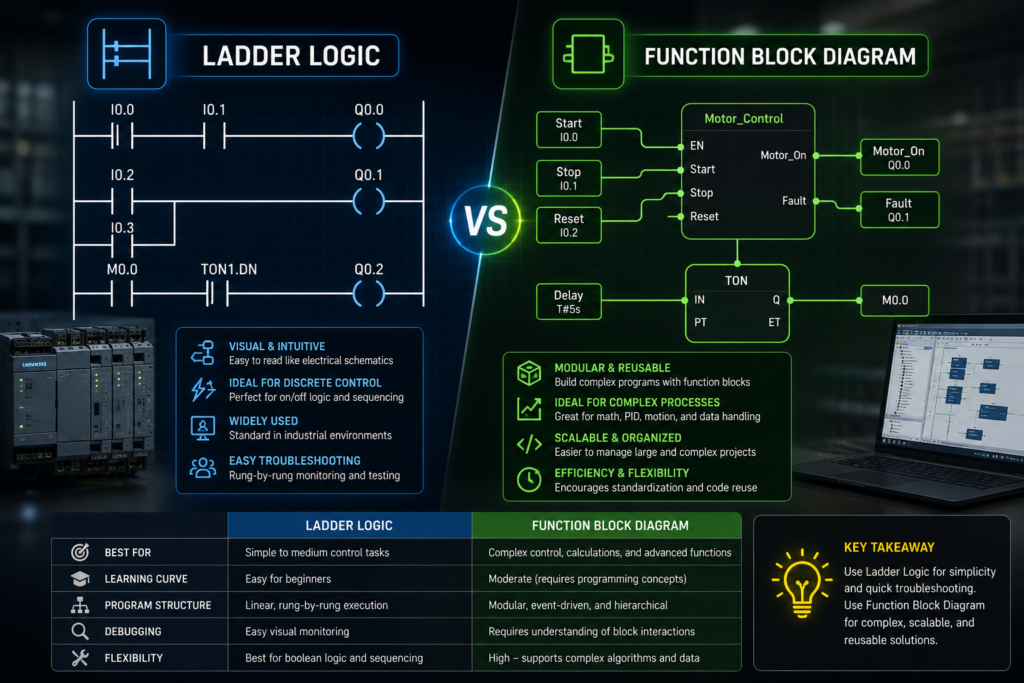
Two engineers, same machine, completely different-looking programs. One screen is covered in rungs that look like a wiring diagram tipped on its side. The other is a flowchart of boxes with lines running between them. Both control the exact same conveyor. Both are correct.
That’s ladder logic and function block diagram — two of the IEC 61131-3 programming languages, both extremely common in the PLC world, and a source of genuine confusion for anyone learning. Which one should you use? Are they interchangeable? Is one just better?
Short answer: they’re different tools for different shapes of problem, and good engineers reach for both. Let me explain what actually separates them, where each shines, and how to decide.
The quick mental model
Before the details, here’s the one-sentence version that’ll orient everything below.
Ladder logic thinks in terms of electrical circuits and boolean conditions — is this true, is that true, therefore energize this. Function block thinks in terms of data flowing through processing blocks — take this value, run it through this function, pass the result to the next one.
Ladder is a descendant of relay wiring. Function block is a descendant of signal-flow diagrams. That heritage explains almost every difference between them.
Ladder logic: electricians feel at home
Ladder logic (LD) is the old guard, and it earned that position. It was deliberately designed to look like the relay control schematics that electricians and technicians already understood when PLCs first replaced banks of physical relays back in the 1970s.
The layout is instantly recognizable once you’ve seen it. Two vertical “rails” down the sides — think of them as power (left) and neutral (right). Between them run horizontal “rungs.” Each rung is a little circuit: a set of conditions on the left that, if satisfied, cause an output on the right to turn on. Power conceptually “flows” left to right through a rung when the conditions make a complete path.
The building blocks are contacts and coils. A contact is a condition — normally-open (-| |-) passes power when its bit is true; normally-closed (-|/|-) passes power when its bit is false. A coil (-( )-) is the output that gets energized when power reaches it. String contacts in series and you’ve built an AND. Put them in parallel branches and you’ve built an OR. That’s the whole grammar, and it maps directly onto how a technician already thinks about a control circuit.
Here’s a rung in plain terms: normally-open Start contact, in parallel with the Motor’s own contact (that’s your seal-in), all in series with a normally-closed Stop contact, driving the Motor coil. Any electrician reads that as a standard start/stop with seal-in without missing a beat. That readability — to the people who actually maintain machines — is ladder’s superpower.
Where ladder shines:
- Discrete, boolean, on/off logic — interlocks, permissives, start/stop circuits, safety conditions
- Anything a maintenance tech will need to read and troubleshoot at 3 a.m. with a meter in hand
- Sequential machine logic where you’re mostly asking “are all these conditions met?”
- Situations where the person maintaining the code came up through the electrical trade
Where ladder gets awkward:
- Heavy math and analog processing — a PID loop or a multi-step calculation crammed into rungs gets ugly fast
- Reusable, self-contained chunks of functionality — ladder doesn’t encapsulate as naturally
- Complex data manipulation, loops, and algorithms
Function block diagram: data flowing through boxes
Function block diagram (FBD) comes at the problem from the other direction. Instead of boolean power flow, it’s about signals and data flowing through functional blocks, wired together like a block diagram in a controls textbook.
Each block is a function: an AND gate, a timer, a PID controller, a scaling block, a counter, an analog comparison. Inputs enter on the left side of the block, the block does its job, and outputs leave on the right — where they can wire straight into the input of the next block. You build behavior by connecting blocks into a flow, output-to-input, until the data has been processed into whatever you need.
The mental picture is a signal chain. An analog input feeds a scaling block, whose output feeds a PID block, whose output feeds an analog output. You can see the data’s journey across the screen — which is exactly why FBD feels natural for process and analog work. The flow on screen mirrors the flow of the actual signal through the system.
Where function block shines:
- Analog and continuous process control — PID loops, scaling, filtering, ratio control
- Complex math and signal processing where you want to see values flowing through a chain
- Reusable, encapsulated functionality — a block hides its internal complexity behind clean inputs and outputs
- Process industries (chemical, water, oil & gas) where signal-flow thinking is the native language
Where function block gets awkward:
- Dense boolean interlock logic — dozens of on/off conditions become a tangle of gate blocks and wires that’s harder to scan than the equivalent rungs
- Troubleshooting by a maintenance crew that grew up on relay logic and finds boxes less intuitive than contacts
- Highly sequential step-by-step logic (though that’s arguably a job for SFC or structured text anyway)
The core differences, side by side
Let me pull the real distinctions into focus, because “one uses rungs, one uses boxes” is only the surface.
Heritage and mindset. Ladder descends from relay wiring and thinks in boolean power flow. FBD descends from signal-flow diagrams and thinks in data moving through functions. This is the root difference from which the others grow.
Best-fit problem type. Ladder is strongest on discrete/boolean logic — the world of true/false, on/off, energized/de-energized. FBD is strongest on analog/continuous processing — the world of values being scaled, controlled, and calculated.
Encapsulation and reuse. This is a big practical one. A function block is genuinely a block — a self-contained unit with defined inputs and outputs that hides its internals. You can build a custom block once (say, a standard motor-control block with all its interlocks and status), then drop instances of it all over your program. Ladder can do reuse through subroutines, but it doesn’t encapsulate as cleanly; the logic tends to live more “in the open.”
Readability — for whom? Neither is objectively more readable; it depends entirely on the reader. To a maintenance electrician, ladder’s contacts-and-coils are transparent and FBD’s blocks are a foreign language. To a process/controls engineer working on loops, FBD’s signal flow is obvious and dense ladder math is a headache. The right choice partly depends on who maintains the machine.
Visual density. Ladder handles many simple boolean conditions compactly — lots of contacts on a rung stays scannable. FBD handles a complex processing chain compactly — a signal path that would be a mess of ladder math becomes a clean left-to-right flow of blocks.
They both compile to the same thing
Here’s the point that resolves a lot of the “which is better” arguing: it doesn’t matter to the PLC.
Both ladder and function block are just human-friendly ways of expressing logic that the controller ultimately executes the same way — scanned, cyclically, in the same scan cycle regardless of which language wrote the instructions. The language is for you, the human, not for the machine. You’re choosing the representation that makes a given problem clearest to the people who’ll read and maintain it.
That’s also why most real programs mix them. A serious machine program will often have ladder handling the discrete interlocks and start/stop logic, function blocks handling the PID loops and analog scaling, and maybe structured text handling a gnarly recipe calculation — all in the same project, each language doing what it’s best at. IEC 61131-3 explicitly allows this, and it’s the norm, not the exception.
So which should you use?
A practical decision guide:
Reach for ladder logic when the problem is fundamentally boolean — interlocks, permissives, motor start/stop, safety conditions, discrete sequencing — and especially when maintenance techs from an electrical background will be the ones troubleshooting it. In discrete manufacturing (automotive, packaging, material handling), ladder is often the house language for exactly these reasons.
Reach for function block when the problem is about processing analog signals or values — PID control, scaling, filtering, ratio and cascade loops, math-heavy signal chains — or when you want reusable encapsulated blocks. In the process industries, FBD is frequently the default for continuous control.
And honestly, learn both. They’re not rivals; they’re complementary. The most capable PLC programmers aren’t the ones who’ve picked a side — they’re the ones who look at a problem, recognize its shape, and pick the language that expresses it most clearly. Discrete interlock? Ladder. Temperature loop? Function block. Both in the same machine? Absolutely, and that’s normal.
The takeaway
Ladder logic and function block diagram aren’t competing answers to the same question — they’re answers to different questions. Ladder speaks the language of relay circuits and boolean conditions, transparent to the electricians who keep machines running. Function block speaks the language of signal flow and data processing, natural for analog control and reusable functionality.
Pick based on the shape of your problem and the background of whoever maintains the result. Boolean and discrete leans ladder. Analog and continuous leans function block. Complex enough to need both? Use both — that’s what the standard is for.
The machine runs them identically either way. The choice is entirely about making the logic clear to the humans. And that’s a choice worth making deliberately.