Level sensors are used to detect or measure the amount of liquid, powder, granules, paste, or other material inside tanks, silos, containers, pipes, and hoppers.
In automation, a level sensor can be used to:
Start and stop pumps
Prevent tank overflow
Protect pumps from dry running
Control filling and emptying
Show tank level on an HMI
Trigger low-level and high-level alarms
Detect product presence
Measure continuous level from 0–100%
When a level sensor gives a wrong signal, the problem is not always the sensor itself.
The fault can come from:
Wrong sensor type
Wrong installation position
Bad power supply
Wrong PLC scaling
Dirty sensing face
Foam
Condensation
Product buildup
Air gap
Wrong teach setting
Blocked pressure port
Wrong tank density setting
False ultrasonic echo
Cable damage
Loose connector
Grounding problem
Analog input fault
Relay output fault
Incorrect configuration
The best way to diagnose level sensor problems is to separate the fault into sections:
Sensor problem
Process problem
Wiring problem
PLC problem
Mechanical installation problem
Configuration problem
Important Safety Note
Level sensors are often installed on tanks, pipes, chemical systems, pressurized vessels, and moving machines.
Before troubleshooting:
Follow lockout/tagout rules.
Check if the tank or pipe is pressurized.
Check if the liquid is hot, toxic, corrosive, flammable, or dangerous.
Wear correct PPE.
Do not remove a sensor from a full or pressurized tank unless the system is isolated and safe.
Do not bypass high-level protection without permission.
Do not use an insulation tester on PLC inputs, sensor electronics, or transmitters unless disconnected and allowed by the manual.
Level sensor faults can cause overflow, dry running, chemical spills, pump damage, or process failure, so diagnose them carefully.
First: Identify the Level Sensor Type
Before measuring anything, identify what kind of level sensor you have.
There are two main categories:
Point level sensor
Continuous level sensor
Point Level Sensor
A point level sensor works like a switch.
It tells the PLC:
Material is present
or
Material is not present
Common output types:
PNP output
NPN output
Relay output
IO-Link switching output
Common point level technologies:
Capacitive
Frequency sweep
Optical
Vibrating fork
Conductive
Float switch
Continuous Level Sensor
A continuous level sensor measures the actual level over a range.
It may output:
4–20 mA
0–10V
IO-Link
Modbus
HART
PROFINET
EtherNet/IP
Common continuous level technologies:
Hydrostatic
Ultrasonic
Potentiometric
Radar
Capacitive continuous probe
Pressure transmitter
The troubleshooting method depends on the sensor type.
A point level switch is diagnosed differently from a 4–20 mA level transmitter.
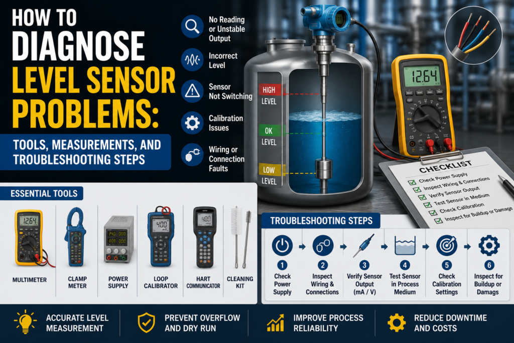
Tools Needed for Level Sensor Troubleshooting
1. Digital Multimeter
This is the first tool to use.
Use it to check:
24V DC power supply
PNP output voltage
NPN output behavior
Relay contact continuity
4–20 mA signal
0–10V signal
Cable continuity
Loose terminals
Grounding problems
Short circuits
A multimeter is enough for many basic level sensor faults.
2. Loop Calibrator / Process Meter
Very useful for continuous level sensors with 4–20 mA output.
Use it to:
Measure loop current
Simulate 4–20 mA into PLC analog input
Check PLC scaling
Check HMI scaling
Prove if the fault is sensor-side or PLC-side
If the sensor display is correct but the PLC value is wrong, use a loop calibrator.
3. Test Magnet or Teach Tool
Some level sensors use a magnetic teach button or external programming tool.
Use it to:
Teach empty state
Teach full state
Set switching threshold
Change output mode
Reset settings
Check sensor status
This is common with capacitive, frequency sweep, and some smart point level sensors.
4. PLC Software
Use PLC software to check:
Digital input status
Analog input raw value
Scaled level value
Alarm logic
HMI tag scaling
Input filtering
Communication status
IO-Link process data
Wrong channel assignment
Many level faults are actually PLC logic or scaling faults.
5. Hand Pump / Pressure Calibrator
Useful for hydrostatic level transmitters.
Use it to apply known pressure and check the output signal.
For water:
1 meter of water ≈ 9.81 kPa
1 meter of water ≈ 0.098 bar
10 meters of water ≈ 0.981 bar
This helps test whether the pressure transmitter output matches the expected tank level.
6. Tape Measure or Ruler
Very useful for ultrasonic and continuous level sensors.
Use it to compare:
Actual distance to liquid surface
Sensor display distance
PLC calculated level
Tank height setting
Simple measurement can quickly find wrong scaling or wrong tank height configuration.
7. Reference Gauge or Manometer
Useful for hydrostatic level measurement.
Use it to compare the real pressure with the transmitter reading.
8. Cleaning Tools
Useful for sensors affected by buildup.
Use suitable cleaning tools depending on the process:
Soft cloth
Approved cleaning liquid
Brush
Water rinse
CIP cleaning procedure
Do not scratch optical tips, capacitive sensing faces, membranes, or pressure diaphragms.
9. Insulation Tester
Use carefully.
It can help find:
Damaged cable insulation
Water in junction boxes
Shorts to ground
Moisture in connectors
But do not megger connected sensor electronics, PLC inputs, or transmitters.
Disconnect first and follow the manufacturer manual.
10. Oscilloscope
Useful for difficult faults caused by noise.
Use it to check:
Analog output noise
Power supply ripple
Switching spikes
Interference from VFDs
Signal drops
Unstable sensor output
Not always needed, but helpful when readings jump randomly.
Common Level Sensor Fault Symptoms
Common symptoms include:
Sensor does not switch
Sensor always ON
Sensor always OFF
Level value stuck at 0%
Level value stuck at 100%
Analog signal stuck at 4 mA
Analog signal stuck at 20 mA
PLC level does not match real tank level
Sensor display correct but PLC wrong
Level reading jumps
False high-level alarm
False low-level alarm
Pump starts and stops too often
Tank overfills
Pump runs dry
Ultrasonic sensor loses echo
Hydrostatic level drifts
Capacitive sensor switches from buildup
Optical sensor does not detect liquid
Sensor only works after cleaning
IO-Link or fieldbus communication fault
Step 1: Check the Real Process Condition
Before blaming the sensor, check the actual tank or pipe.
Ask:
Is there really material at the sensor?
Is the tank full or empty?
Is the pipe full?
Is the liquid foaming?
Is there product buildup?
Is the sensor covered by material?
Is the level changing?
Is the pump running?
Are valves open?
Is there pressure in the tank?
Is the material density correct for the setup?
A sensor can only measure the condition at its installation point.
If the sensor is installed in a dead zone, air pocket, foam layer, or blocked area, the reading may not represent the real tank level.
Step 2: Check the Local Display or Status LED
Many sensors have LEDs or displays.
Check:
Power LED
Output LED
Alarm LED
Teach status
Echo status
Error code
Local level value
Distance value
Temperature value
Diagnostic message
If the Sensor Display Is Correct but PLC Is Wrong
The problem is probably in:
Wiring
PLC input
Analog scaling
HMI scaling
Communication mapping
Wrong units
Wrong channel
If the Sensor Display Is Wrong Too
The problem may be in:
Sensor installation
Sensor contamination
Wrong teach setting
Wrong range
Wrong sensor type
Process condition
Power supply
Sensor failure
Step 3: Check Power Supply
Most industrial level sensors use 24V DC.
Measure voltage at the sensor terminals, not only at the power supply.
Good 24V DC Reading
For many industrial sensors:
20.4V DC to 28.8V DC is usually acceptable.
That is 24V ±20%.
Always check the sensor datasheet.
Bad Readings
0V
Wrong polarity
Below allowed voltage
Unstable voltage
Voltage drops when output switches
High AC ripple
Loose 0V/common wire
Shared power supply overloaded
Measure voltage while the sensor is connected.
A weak power supply can look normal with no load but fail during operation.
Step 4: Check Point Level Sensor Output
Point level sensors usually switch a PLC digital input.
Common output types:
PNP
NPN
Relay
PNP Output Test
A PNP sensor switches positive voltage to the PLC input.
When the sensor output is ON, the output wire should be close to +24V DC.
Good PNP Measurements
Output OFF: usually around 0V or floating, depending on wiring
Output ON: usually around +24V DC
PLC input ON when output is ON
Sensor LED matches PLC input
Bad PNP Measurements
Output never reaches +24V
Output stuck at +24V
Output voltage present but PLC input not ON
Voltage drops when load connected
Wrong PLC input common
Broken output wire
Output shorted
NPN Output Test
An NPN sensor switches the output to 0V.
When the sensor output is ON, it pulls the PLC input down to 0V.
Good NPN Measurements
Output OFF: usually pulled high through PLC input circuit
Output ON: near 0V DC
PLC input ON when output is pulled low
Correct PLC input type used
Bad NPN Measurements
Wrong input type
Output does not pull low
Output stuck at 0V
PLC input wired for PNP but sensor is NPN
No pull-up path
Broken common wire
PNP and NPN mistakes are very common.
A good sensor will not work correctly if connected to the wrong PLC input type.
Relay Output Test
Some level switches have relay contacts.
Check whether you are using NO or NC contact.
Good Relay Measurements
NO contact inactive: open circuit
NO contact active: closed contact
NC contact inactive: closed contact
NC contact active: open circuit
A closed relay contact should usually measure very low resistance, often below 1 Ω plus test lead resistance.
Bad Relay Measurements
Contact always open
Contact always closed
Wrong NO/NC terminal used
Contact resistance high
Relay output overloaded
PLC input wired incorrectly
Relay function configured wrong
Step 5: Check 4–20 mA Output
Continuous level sensors often use 4–20 mA.
Typical scaling:
| Level | Expected Current |
|---|---|
| 0% | 4 mA |
| 25% | 8 mA |
| 50% | 12 mA |
| 75% | 16 mA |
| 100% | 20 mA |
Example:
If tank level range is:
0–2 meters = 4–20 mA
Then:
0 m = 4 mA
1 m = 12 mA
2 m = 20 mA
Good 4–20 mA Measurements
Around 4 mA at 0%
Around 12 mA at 50%
Around 20 mA at 100%
Signal changes smoothly with level
Measured current matches sensor display and PLC value
Bad 4–20 mA Measurements
| Reading | Possible Problem |
|---|---|
| 0 mA | Broken loop, no power, wrong wiring |
| Below 3.6 mA | Fault alarm on many devices |
| 4 mA all the time | Empty level, output stuck, wrong setup |
| 20 mA all the time | Full level, saturated output, wrong setup |
| Above 21 mA | Fault alarm or overrange on many devices |
| Jumping current | Noise, unstable process, loose wire |
| Display correct but mA wrong | Output configuration problem |
| mA correct but PLC wrong | PLC scaling problem |
Alarm current depends on sensor configuration.
Step 6: Check 0–10V Output
Some continuous level sensors use 0–10V.
Typical scaling:
| Level | Expected Voltage |
|---|---|
| 0% | 0V |
| 25% | 2.5V |
| 50% | 5V |
| 75% | 7.5V |
| 100% | 10V |
Good Voltage Output
0V at 0%
5V at 50%
10V at 100%
Smooth change with level
PLC value matches measured voltage
Bad Voltage Output
0V all the time
10V all the time
Voltage unstable
Voltage drops when connected to PLC
Correct voltage but wrong PLC value
Signal affected by motor or VFD operation
Voltage signals are more sensitive to cable length and noise than 4–20 mA.
Step 7: Simulate the PLC Input
If the sensor output is correct but the PLC value is wrong, test the PLC input.
Use a loop calibrator or signal simulator.
For 4–20 mA:
| Simulated Current | PLC Should Show |
|---|---|
| 4 mA | 0% |
| 8 mA | 25% |
| 12 mA | 50% |
| 16 mA | 75% |
| 20 mA | 100% |
For 0–10V:
| Simulated Voltage | PLC Should Show |
|---|---|
| 0V | 0% |
| 2.5V | 25% |
| 5V | 50% |
| 7.5V | 75% |
| 10V | 100% |
If the PLC does not show the correct value, the problem is probably:
PLC scaling
Analog input configuration
HMI scaling
Wrong input channel
Wrong signal type
Wrong engineering range
Step 8: Check PLC Scaling
PLC scaling mistakes are very common.
Check:
4–20 mA or 0–20 mA setting
0–10V or 2–10V setting
Raw input range
Engineering range
Tank height
Distance vs level calculation
Units: mm, cm, m, %, liters
Inverted scaling
Wrong analog channel
Wrong HMI tag
Wrong decimal point
Common Mistake With Ultrasonic Sensors
Ultrasonic sensors often measure distance, not level.
If the sensor output increases when the distance increases, the PLC must convert distance into level.
Formula:
Level = Tank height – measured distance
If this is done wrong, the PLC may show empty when the tank is full.
Step 9: Check Sensor Teach or Configuration
Many level sensors need setup.
Check:
Empty teach
Full teach
Switching threshold
Output mode: NO or NC
PNP or NPN type
Damping/filter setting
Fail-safe output state
Analog range
Tank height
Offset
Medium type
Sensitivity
Echo settings
Density setting
Temperature compensation
Communication address
Bad Configuration Symptoms
Sensor switches too early
Sensor switches too late
Sensor does not switch at all
Analog output inverted
Level stuck at 0% or 100%
PLC value scaled correctly but process value wrong
Sensor works on water but not product
High alarm activates at wrong level
Step 10: Diagnose Capacitive Level Sensor Problems
Capacitive sensors detect changes in capacitance caused by material near the sensor.
They can detect liquids, powders, granules, and sometimes material through plastic or glass walls.
Common Capacitive Sensor Problems
Sensor face coated with product
Moisture on sensing face
Wrong sensitivity
Wall too thick for through-wall detection
Medium dielectric constant too low
Metal tank interfering with detection
Foam or buildup causing false switching
Sensor installed too far from material
Wrong teach setting
Good Checks
Sensor switches when material reaches sensing area
Status LED changes correctly
Output voltage matches LED state
Teach setting stable
Sensing face clean
Wall thickness suitable
Sensor detects product repeatedly
Bad Signs
Sensor always ON because of buildup
Sensor never ON because sensitivity too low
False switching from moisture
Detection through wall unreliable
Output LED changes but PLC does not
Sensor works by hand test but not in tank
A hand test is useful, but not enough. A capacitive sensor may detect your hand but still fail to detect the actual medium if the dielectric properties are different.
Step 11: Diagnose Frequency Sweep Level Sensor Problems
Frequency sweep sensors detect changes in resonance caused by the medium around the sensor tip.
They are used for point level detection in liquids, powders, sticky products, and foam.
Common Problems
Wrong switching threshold
Sensor not taught with real medium
Heavy buildup on sensor tip
Foam detected when not wanted
Sensor installed in dead zone
Air pocket around sensor
Product does not contact sensor tip
Incorrect output mode
Wrong damping setting
Good Checks
Sensor changes state when real product reaches the tip
Output LED matches PLC input
Sensor can be taught empty and full
Switch point is repeatable
Sensor remains stable during normal buildup
Correct fail-safe mode selected
Bad Signs
Sensor switches from residue only
Sensor ignores real material
Sensor changes state randomly
Sensor cannot complete teach procedure
Sensor works in water test but not with actual product
Sensor installed where product bridges or sticks permanently
For these sensors, correct teach-in with the actual process medium is very important.
Step 12: Diagnose Optical Level Sensor Problems
Optical level sensors use light reflection or refraction to detect liquid.
They are usually point level sensors.
Common Problems
Dirty optical tip
Scratched sensor tip
Foam on tip
Air bubbles
Product coating
Condensation
Wrong mounting angle
Liquid film remains after tank drains
Sensor cannot detect very dark or sticky product reliably
External hose sensor misaligned
Good Checks
Sensor switches clearly in air and in liquid
Optical tip is clean
LED/output changes correctly
No bubbles trapped on sensing tip
Output matches PLC input
Sensor repeats correctly after several wet/dry cycles
Bad Signs
Sensor always detects liquid because film remains on tip
Sensor never detects liquid because tip is coated
False switching from foam or bubbles
Sensor works when cleaned but fails after process run
External optical sensor moves on hose
Sensor cannot see through dirty tube wall
Optical sensors need a clean optical path.
If the tip is coated, the sensor may give wrong results.
Step 13: Diagnose Potentiometric Level Sensor Problems
Potentiometric level sensors measure continuous level in conductive liquids.
They usually use a probe rod and a reference through the tank wall or process connection.
Common Problems
Liquid not conductive enough
Poor tank grounding
Probe coated
Wrong probe length setting
Wrong reference connection
Plastic tank without proper reference electrode
Foam or product buildup
Wrong 4–20 mA scaling
Sensor not inserted correctly
Probe damaged or bent
Good Checks
Liquid conductivity is above sensor minimum
Probe is clean
Tank or reference electrode is properly connected
Level output changes smoothly with filling
4–20 mA signal matches local display
0%, 50%, and 100% levels scale correctly
Bad Signs
Reading unstable in conductive liquid
No level change when tank fills
Output jumps when grounding changes
Sensor works in metal tank but not plastic tank
Probe coating causes slow response
Level wrong after probe replacement
PLC value does not match transmitter display
Potentiometric sensors need correct liquid conductivity and reference conditions.
Step 14: Diagnose Hydrostatic Level Sensor Problems
Hydrostatic level sensors measure liquid level by measuring pressure at the bottom of the tank.
The formula is:
p = ρ × g × h
Where:
p = pressure
ρ = liquid density
g = gravity
h = liquid height
For water:
1 meter water column ≈ 9.81 kPa ≈ 0.098 bar
Good Hydrostatic Checks
Pressure matches liquid height
4–20 mA output matches pressure range
Sensor zero is correct when tank is empty
Vent tube is clear for gauge sensors
Density setting matches liquid
No blockage at pressure port
No leaks in impulse line
Output changes smoothly with level
Bad Hydrostatic Signs
Level reads high when tank is empty
Level reads low when tank is full
Pressure port blocked with sludge
Vent tube blocked or wet
Density setting wrong
Sensor installed at wrong height
Closed tank pressure not compensated
Output drifts over time
Diaphragm damaged
Cable vent blocked in submersible sensor
Example Pressure Check
Tank has 2 meters of water.
Expected pressure at bottom:
2 × 9.81 kPa = 19.62 kPa
That is approximately:
0.196 bar
If the pressure transmitter is scaled:
0–2 m water = 4–20 mA
Then at 1 meter water:
Expected current = 12 mA
At 2 meters water:
Expected current = 20 mA
If the tank is full but the signal is only 8 mA, check scaling, density, pressure port blockage, and sensor range.
Step 15: Diagnose Ultrasonic Level Sensor Problems
Ultrasonic sensors measure distance using sound waves.
They are usually mounted above the material.
Common Problems
Foam absorbs sound
Steam disturbs signal
Dust weakens echo
Turbulent surface
False echo from tank wall or ladder
Obstacle in beam path
Sensor mounted too close to wall
Sensor not perpendicular to surface
Dead zone violation
Condensation on sensor face
Wrong tank height setting
Wrong distance-to-level conversion
Temperature compensation problem
Good Ultrasonic Checks
Measured distance matches tape measurement
Echo signal is stable
Sensor is aimed at the surface
No obstacles in beam path
Level changes smoothly
Blanking/dead zone respected
Output matches configured range
PLC correctly converts distance to level
Bad Signs
Lost echo alarm
Distance jumps randomly
Level changes when mixer starts
False full reading from foam
False low reading from weak echo
Sensor reads an internal tank obstacle
Condensation causes signal loss
PLC shows inverted level
Sensor stuck at minimum or maximum
Distance Check Example
Tank height: 3 meters
Measured distance from sensor to liquid: 1 meter
Actual level:
3 – 1 = 2 meters
If the sensor display shows 1 meter distance but PLC shows 1 meter level, the PLC calculation is probably wrong.
Step 16: Check Cable and Connector
Level sensors often fail because of cable damage.
Check:
Crushed cable
Cut insulation
Loose connector
Water inside connector
Chemical damage
Corrosion
Loose terminal
Broken shield
Cable pulled tight
Bad cable gland
Sensor cable routed beside VFD cable
Good Cable Condition
No physical damage
Connector dry
Terminals tight
No corrosion
Signal stable when cable is moved
Shield connected correctly
Bad Cable Condition
Signal jumps when cable is touched
Water in connector
Green corrosion
Broken conductor
Intermittent output
Short between wires
Short to ground
Connector not sealed
Move the cable gently while watching the signal.
If the output jumps, suspect cable or connector damage.
Step 17: Check Insulation Resistance
Insulation faults can cause unstable signals and false switching.
Disconnect the sensor from electronics before testing.
General Practical Values
| Insulation Resistance | Meaning |
|---|---|
| >100 MΩ | Very good |
| 20–100 MΩ | Usually acceptable, check manual |
| 1–20 MΩ | Suspicious |
| <1 MΩ | Usually bad |
Low insulation can be caused by:
Water in connector
Damaged cable
Chemical ingress
Cracked housing
Condensation
Poor cable gland
Wet junction box
Do not insulation-test sensitive sensor electronics unless the manufacturer allows it.
Step 18: Check Grounding and Shielding
Noise can create false signals or unstable analog values.
Common noise sources:
VFD motor cables
Servo drives
Large contactors
Solenoid valves
Welding equipment
Poor panel grounding
Long analog cables
Incorrect shield grounding
Good
Shield connected according to manual
Sensor cable separated from power cables
Panel ground is good
No high ground potential difference
Analog signal stable
No switching when motors start
Bad
Sensor output jumps when VFD runs
Level value changes with motor speed
Cable routed with motor cable
Shield disconnected
Ground difference above about 1V AC or DC
Analog signal noisy
False switching from contactor operation
Measure voltage between sensor body, tank, machine frame, and panel PE.
Ideally it should be close to 0V.
More than about 1V AC or DC between grounding points is suspicious.
Step 19: Check IO-Link or Digital Communication
Smart level sensors may use IO-Link or fieldbus communication.
Common problems:
Wrong device address
Wrong IO-Link port configuration
Wrong process data mapping
PLC reading wrong byte
Wrong scaling factor
Wrong units
Wrong switching bit
Parameter set missing
Sensor replaced but not reparameterized
Communication timeout
Wrong sensor profile
If the local sensor display is correct but PLC data is wrong, check mapping and parameterization.
Step 20: Troubleshooting by Symptom
Sensor Does Not Switch
Possible causes:
No power
Wrong output type
Wrong PLC input type
Wrong teach setting
Material not reaching sensor
Sensor too far from product
Medium not suitable
Sensor face dirty
Cable broken
Checks:
Measure power
Check LED status
Measure output voltage
Test PLC input
Check teach setting
Test with actual material
Inspect sensor face
Sensor Always ON
Possible causes:
Product buildup
Moisture on sensor
Wrong sensitivity
Wrong NO/NC setting
Shorted output wire
Relay contact stuck
Foam or residue
Sensor damaged
Checks:
Clean sensor
Check output voltage
Disconnect output and test sensor
Check NO/NC setting
Inspect cable
Retune sensor
Sensor Always OFF
Possible causes:
No power
Wrong wiring
Material not detected
Sensitivity too low
Sensor too far from medium
Wrong sensor technology
Broken output
PLC input fault
Checks:
Measure supply voltage
Check sensor LED
Measure output
Test PLC input manually
Retune sensor
Try real material test
Continuous Level Stuck at 0%
Possible causes:
4 mA output only
Empty tank
Wrong zero setting
Broken analog loop
Sensor not detecting level
Ultrasonic lost echo
Hydrostatic pressure port blocked
Wrong PLC scaling
Checks:
Measure mA
Check local display
Check real level
Simulate PLC input
Check sensor diagnostics
Check installation
Continuous Level Stuck at 100%
Possible causes:
20 mA output only
Tank full
Sensor saturated
Wrong range
False ultrasonic echo
Blocked hydrostatic sensor
Wrong density setting
PLC scaling wrong
Checks:
Measure mA
Check local display
Check real level
Check range settings
Check echo/distance
Check hydrostatic pressure
Level Reading Jumps
Possible causes:
Foam
Turbulence
Electrical noise
Loose cable
Bad grounding
Ultrasonic false echoes
Product buildup
Air bubbles
Unstable process
Wrong damping
Checks:
Inspect process
Check cable
Check shielding
Check sensor diagnostics
Check damping/filter
Move cable gently
Watch signal when motors start
PLC Value Wrong but Sensor Display Correct
Possible causes:
Wrong analog scaling
Wrong units
Wrong HMI tag
Wrong input channel
Wrong 4–20 mA range
Wrong distance-to-level conversion
Wrong digital mapping
Checks:
Measure output signal
Simulate PLC input
Check raw analog value
Check HMI scaling
Check communication data
Quick Measurement Table
| Test | Good Measurement | Bad Measurement |
|---|---|---|
| 24V DC supply | Usually 20.4–28.8V DC | Missing, low, unstable, reversed |
| PNP output ON | Near +24V DC | Low voltage, unstable, no change |
| NPN output ON | Near 0V DC | Does not pull low |
| Relay closed | Usually <1 Ω plus leads | High resistance, open |
| Relay open | OL / open circuit | Stuck closed |
| 4–20 mA at 0% | Around 4 mA | 0 mA, alarm current |
| 4–20 mA at 50% | Around 12 mA | Wrong current for level |
| 4–20 mA at 100% | Around 20 mA | Saturated or wrong scaling |
| 0–10V at 50% | Around 5V | Wrong voltage or unstable |
| Hydrostatic water pressure | 1 m ≈ 9.81 kPa | Does not match liquid height |
| Ultrasonic distance | Matches tape measurement | Lost echo or false distance |
| Insulation resistance | >100 MΩ very good | <1 MΩ usually bad |
| Ground difference | Close to 0V | >1V suspicious |
| PLC simulation | 4/12/20 mA scales correctly | PLC scaling/input problem |
What Measurements Are Usually Good?
These are general practical values:
24V DC supply around 20.4–28.8V DC
PNP output ON close to +24V DC
NPN output ON close to 0V DC
Relay closed contact below about 1 Ω plus lead resistance
4 mA at 0% level
12 mA at 50% level
20 mA at 100% level
0V at 0% for 0–10V output
5V at 50% for 0–10V output
10V at 100% for 0–10V output
1 meter water column near 9.81 kPa
Ultrasonic distance close to measured tape distance
Insulation resistance above 100 MΩ is very good
Ground voltage difference close to 0V
PLC value matches measured signal after scaling
What Measurements Are Usually Bad?
These readings usually indicate a problem:
0V power supply
24V supply below allowed range
Wrong polarity
PNP output not reaching high voltage
NPN output not pulling low
Relay contact high resistance when closed
4–20 mA output at 0 mA
Output below 3.6 mA or above 21 mA without known reason
4 mA all the time while level changes
20 mA all the time while level is normal
0–10V output stuck at 0V or 10V
Hydrostatic pressure not matching actual liquid height
Ultrasonic distance not matching real distance
Insulation resistance below 1 MΩ
Level signal jumps when cable is touched
Level changes when VFD starts
PLC value different from measured mA or voltage
Sensor LED changes but PLC input does not
Practical Diagnostic Order
When diagnosing a level sensor, I would follow this order:
- Identify sensor type: point or continuous.
- Identify technology: capacitive, optical, hydrostatic, ultrasonic, potentiometric, frequency sweep.
- Check the real tank or pipe condition.
- Check local display, LEDs, and alarm messages.
- Measure power supply voltage.
- For point sensors, measure PNP/NPN/relay output.
- For continuous sensors, measure 4–20 mA or 0–10V output.
- Compare sensor display with PLC/HMI value.
- Simulate PLC input to prove scaling.
- Check PLC units, range, and logic.
- Check teach settings, thresholds, and output mode.
- Inspect and clean the sensing area.
- Check process problems: foam, buildup, air, dust, turbulence, sludge.
- Check cable, connector, and terminals.
- Check insulation resistance if allowed.
- Check grounding and shielding.
- For hydrostatic sensors, verify pressure vs liquid height.
- For ultrasonic sensors, verify distance with tape and check echo.
- For potentiometric sensors, check conductivity and reference/ground.
- For smart sensors, check IO-Link or digital mapping.
This order helps avoid replacing a good sensor when the real problem is wiring, setup, scaling, buildup, or process conditions.
Final Thoughts
Level sensor troubleshooting is both an electrical and process task.
A sensor may be electrically healthy but still give a bad reading because of foam, product buildup, blocked pressure port, false ultrasonic echo, wrong tank height, wrong density setting, poor grounding, or wrong PLC scaling.
The most useful tools are:
Digital multimeter
Loop calibrator
PLC software
Pressure calibrator
Tape measure
Reference pressure gauge
Cleaning tools
Insulation tester
Oscilloscope
Sensor configuration tool
The key idea is simple:
If the sensor display is correct but the PLC value is wrong, check wiring and scaling.
If the sensor value is wrong but the output signal matches it, check installation, process conditions, and configuration.
If the sensor output is electrically wrong, check power, cable, output type, and sensor electronics.
Do not diagnose level sensors only from the PLC screen.
Check the real tank, the sensor display, the output signal, and the PLC scaling step by step.