A miniature circuit breaker, usually shortened to MCB, is one of the most familiar protective devices inside an electrical panel. It may look simple—a plastic body, a small operating lever and a few screw terminals—but its job is important.
An MCB automatically disconnects a circuit when the current becomes dangerously high.
This normally happens because of:
- An overload
- A short circuit
- A serious wiring or equipment fault
By interrupting the current, the breaker helps protect cables, equipment and the electrical installation from overheating and possible fire damage.
An MCB primarily protects the circuit conductors. It should not be confused with an RCD or RCBO, which can also provide protection against earth-leakage current and electric shock.
How an MCB Works
Inside the breaker are two main tripping mechanisms.
The thermal trip responds to overloads. If current remains above the breaker’s rated value for a period of time, a bimetallic element heats up, bends and opens the contacts.
The magnetic trip reacts much faster. During a short circuit, the current rises sharply, creating a strong magnetic force that trips the breaker almost instantly.
After the fault has been repaired, an MCB can normally be reset using its operating lever. Unlike a fuse, it does not usually need to be replaced after every trip.
However, repeatedly resetting a breaker without finding the cause is not a repair. If it trips again, something in the circuit is still wrong.
Single-Pole MCB
A single-pole MCB switches and protects one conductor.
It is commonly used for single-phase branch circuits where only the phase conductor is disconnected.
Typical terminal numbering is:
- Terminal 1: incoming conductor
- Terminal 2: outgoing conductor
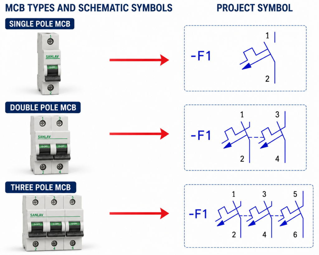
On a schematic, the single switching contact is shown together with the breaker’s trip mechanism.
The device in the drawing may be labelled -F1, although component reference letters vary between companies and electrical-drawing standards. In some projects, circuit breakers may instead use a designation such as QF.
Double-Pole MCB
A double-pole MCB contains two mechanically linked poles.
When the breaker trips or is switched off, both poles open together. It may be used to disconnect:
- Phase and neutral
- Two live conductors
- Two phases in an appropriate circuit
Typical terminal numbering is:
- 1–2 for the first pole
- 3–4 for the second pole
The two poles are linked mechanically, so one fault causes both contacts to open. This provides simultaneous isolation rather than relying on two separate single-pole breakers.
A double-pole device should not be confused with two unrelated breakers installed beside each other. Proper mechanical linkage is important when both conductors must disconnect together.
Three-Pole MCB
A three-pole MCB is mainly used in three-phase circuits.
It protects and disconnects all three phases simultaneously. Common applications include:
- Three-phase motors
- Industrial machines
- Distribution circuits
- Pumps, fans and compressors
- Small three-phase control panels
Typical terminal numbering is:
- 1–2 for phase one
- 3–4 for phase two
- 5–6 for phase three
The three contacts are mechanically linked. If one pole detects a sufficiently high fault current, the breaker opens all three phases.
This prevents a three-phase load from continuing to operate with only one or two phases connected.
Understanding the Schematic Symbol
The project symbol shows the number of switching poles and the mechanical connection between them.
Important details include:
- The angled contact represents the switching element.
- The trip mechanism indicates automatic overcurrent protection.
- Dashed or linked lines show that the poles operate together.
- Terminal numbers identify incoming and outgoing connections.
- The reference designation identifies the breaker in drawings and component lists.
For example, a three-pole breaker may show terminal pairs 1–2, 3–4 and 5–6.
Terminal numbering should always be confirmed from the manufacturer’s markings and project documentation. Some installations use different conventions, especially for DC systems or specialized breakers.
Selecting the Correct MCB
Choosing an MCB involves more than matching its rated current to the load.
The designer should also consider:
- Cable current-carrying capacity
- Short-circuit breaking capacity
- Trip curve, such as B, C or D
- Number of poles
- Supply voltage
- AC or DC application
- Prospective short-circuit current
- Coordination with upstream protection
- Starting current of motors or transformers
An oversized breaker may fail to protect the cable properly. A breaker with an unsuitable trip curve may nuisance-trip whenever a motor starts.
Final Thoughts
Single-, double- and three-pole MCBs follow the same basic principle: they disconnect a circuit when excessive current is detected.
The main difference is the number of conductors switched together.
Understanding the pole arrangement, schematic symbol and terminal numbering makes electrical drawings easier to read and helps prevent wiring mistakes during panel assembly or maintenance.