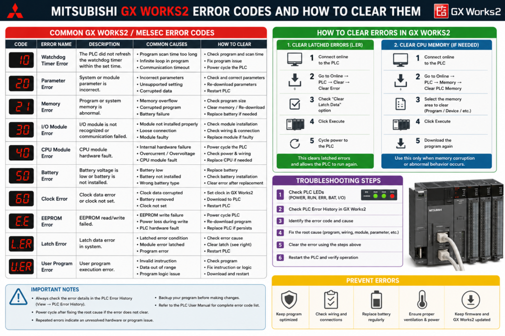
GX Works2 shows an error code. The PLC’s ERR light is flashing. Production has stopped.
The natural reaction is to search the number, press Reset and hope the controller returns to RUN.
That approach sometimes works—for approximately five seconds.
The difficult part is that a “GX Works2 error” can come from several different places:
- The GX Works2 programming software
- The PLC CPU
- A communication connection
- An intelligent function module
- The ladder program
- PLC parameters
- An FX-series special error register
The same troubleshooting method does not apply to all of them. A compile error such as F1028 does not require a PLC reset. A Q-series WDT ERROR does. An FX-series communication timeout may allow the PLC to continue running even though GX Works2 reports a problem.
This guide explains how to identify common Mitsubishi GX Works2 error codes, correct their causes and clear them safely.
Safety warning: Resetting a PLC may return it to RUN according to the position of its physical mode switch. Outputs and connected machinery may operate immediately. Place the equipment in a safe state before writing parameters, resetting the CPU or restoring power.
Quick Error-Code Reference
| Code or message | PLC family or source | Meaning | First thing to check |
|---|---|---|---|
| F1028 | GX Works2 | Label auto-assignment device conflict | Label device range |
| 2100 | Q/L series | SP.UNIT LAY ERR. | Physical modules versus I/O assignment |
| 2200 | Q series | MISSING PARA. | Parameter file missing from valid memory |
| 2400 | Q series | FILE SET ERROR | Program or file specified in parameters is missing |
| 3000 | Q series | PARAMETER ERROR | Invalid or inconsistent PLC parameters |
| 4100 | Q series | OPERATION ERROR | Invalid runtime calculation, such as division by zero |
| 4101 | Q/L series | OPERATION ERROR | Indexed device outside its valid range |
| 5000/5001 | Q series | WDT ERROR | Scan or interrupt execution exceeds watchdog |
| 5010 | Q series | PRG.TIME OVER | Program scan exceeds configured constant-scan time |
| 3806/6306 | FX series | Communication timeout | Port parameters, cable or connected device |
| 6105 | FX series | Watchdog timer error | Excessive scan time or program loop |
| 6401–6409 | FX series | Parameter errors | PLC parameter configuration |
| 6501–6509 | FX series | Syntax errors | Incorrect instruction or device |
| 6610 and above | FX series | Ladder/circuit errors | Invalid ladder structure |
| 6701 and above | FX series | Operation errors | Runtime operands, pointers or indexed devices |
These codes are not universal across every Mitsubishi controller. Always confirm the exact CPU model and consult the diagnostic details shown for that controller.
First: Is It a Software Error or a PLC Error?
Before resetting anything, determine where the message appeared.
GX Works2 software error
These errors usually appear while you:
- Convert or compile the project
- Enter an instruction
- Configure labels
- Write project data
- Open or save a file
The PLC may still be operating normally.
Communication error
These appear when GX Works2 cannot reach the controller.
Examples include:
- Communication timeout
- Cannot communicate with PLC
- An unusable COM port was specified
- Connection test failed
- USB driver not found
The PLC may still be running its program perfectly well.
PLC diagnostic error
These are generated by the CPU’s self-diagnostic system. They normally appear under:
Diagnostics
→ PLC Diagnostics
Q-series CPUs store current diagnostic information in special registers such as SD0. FX3 controllers use special registers including D8004 and D8060 through D8067.
Resetting the programming software will not clear a genuine CPU diagnostic error.
How to Check a PLC Error in GX Works2
Connect to the correct PLC and open:
Diagnostics
→ PLC Diagnostics
GX Works2 displays the PLC’s status, current error and available error details. On supported FX controllers, the same screen displays the CPU’s LED state and diagnostic result, with access to the related help information.
Record the following before clearing anything:
PLC model:
Error code:
Error message:
Individual error information:
Program step:
Module slot or start I/O:
CPU mode:
ERR LED state:
Time fault occurred:
Recent program or hardware changes:
Do not record only “parameter error.” The individual information may identify the exact parameter, file, program step or module involved.
Check the error history
The latest error is not always the original fault.
One problem can generate several secondary errors. For example, a module failure may produce a module error, communication error and downstream program alarm.
QnU CPUs retain diagnostic error history that can be viewed through PLC Diagnostics. The history can remain available after power loss when supported by the controller and its backup system.
Clear the history only after recording it.
Deleting the error history does not repair the active problem. It merely removes the evidence.
Common GX Works2 and Mitsubishi PLC Errors
F1028: GX Works2 Compilation Error
F1028 is a GX Works2 software error associated with projects that use labels.
It occurs when a device used directly in the program overlaps the device range reserved for automatic label assignment.
For example, suppose automatic label assignment uses:
D1000 to D1999If the program also directly uses D1200, GX Works2 may detect the conflict during conversion.
Mitsubishi’s corrective action is to either:
- Change the directly used device to one outside the automatic-assignment area, or
- Change the automatic-assignment device range.
How to clear F1028
- Open the label or automatic device-assignment settings.
- Identify the reserved device range.
- Search the project for direct use of devices inside that range.
- Move the conflicting device or change the assignment range.
- Convert or rebuild the project again.
No PLC reset is required because F1028 is a project-conversion error.
Do not write an unconverted project to the controller.
Error 2100: SP.UNIT LAY ERR.
Error 2100 means the intelligent function module configuration does not agree with the physical PLC arrangement.
Common causes include:
- An intelligent function module configured as ordinary I/O
- An I/O module configured as an intelligent module
- Incorrect CPU or empty-slot assignment
- Too few I/O points assigned to a module
- Switch settings entered for a module that does not support them
Mitsubishi’s remedy is to correct the I/O assignment so that the configured module type and point count match the modules physically mounted in the system.
How to fix error 2100
In GX Works2, open the PLC parameters and inspect the I/O assignment.
Compare every configured slot with the actual rack:
Slot 0: QX input module
Slot 1: QY output module
Slot 2: Q64AD analog input
Slot 3: Empty
Check:
- Exact catalog number
- Module category
- Assigned I/O points
- Start I/O number
- Switch settings
- Empty slots
- Extension-base arrangement
Correct the assignment, write the parameters and perform the required CPU reset or power cycle.
Do not change the configuration simply to make the error disappear. Confirm what is physically installed first.
Error 2200: MISSING PARA.
Error 2200 means the CPU cannot find a valid parameter file in the memory location from which it expects to load parameters.
Depending on the Q-series CPU, the valid location may be determined by the CPU configuration, memory settings or hardware switches. Mitsubishi’s stated remedy is to write a valid parameter file to the required PLC drive or correct the selected parameter-valid memory.
Common causes
- Parameters were not included in the last download
- PLC memory was cleared
- CPU or memory card was replaced
- Hardware switches point to the wrong memory
- Boot configuration is incorrect
- A project was written only partially
- Memory contents were lost or corrupted
How to clear error 2200
- Confirm the correct project and CPU model.
- Open Write to PLC.
- Ensure PLC parameters are selected.
- Verify the destination memory.
- Write the parameters.
- Reset the CPU.
- Confirm that the PLC returns without the error.
Be extremely careful before downloading a complete project. When only the parameters are missing, do not overwrite a valid running program with an old offline file unless you have verified the project.
Error 2400: FILE SET ERROR
Error 2400 means a file specified by the PLC parameters cannot be found.
For example, the program settings may specify a program file that does not exist in the CPU. Mitsubishi notes that individual error information such as parameter number 7000H can point to the program-setting area. The program names configured in the parameters must match the files stored in the controller.
Common causes
- Program renamed offline but parameters not updated
- Program file omitted from the download
- File deleted from PLC memory
- Incorrect boot-file configuration
- Memory card missing
- Project copied from a different machine
- Wrong program enabled in the execution settings
How to clear error 2400
Open the program-execution and PLC file settings.
Compare:
Programs configured in parameters
versus
Programs present in project and PLC memory
Correct the file name or write the missing file. Then reset the controller.
A related Q-series code, 2401, can occur when a configured file-register file cannot be created because the destination memory does not have enough free capacity.
Error 3000: PARAMETER ERROR
Error 3000 is a general Q-series parameter error.
The CPU checks parameters during power-up, reset, transition from STOP to RUN and certain write operations. A detected parameter inconsistency may stop the controller and flash the ERR indicator. Mitsubishi documents that additional parameter numbers stored in diagnostic registers can identify the affected setting.
Possible causes
- I/O assignment conflict
- Invalid device range
- Incorrect memory allocation
- Network parameters outside the permitted range
- Unsupported setting for the selected CPU
- Overlapping file-register or latch areas
- Configuration created for a different CPU model
- Partial or corrupted parameter download
How to troubleshoot error 3000
Do not begin by rebuilding every parameter page.
Open the error’s Individual Information and identify the parameter number. Then inspect that section only.
Also check whether the project’s selected PLC type matches the real CPU:
Project
→ Change PLC Type
A project configured for a similar but different CPU may accept settings that the installed controller cannot use.
Correct the setting, convert the project, write the required parameters and reset the CPU.
Error 4100: OPERATION ERROR
Error 4100 occurs while the CPU executes the program.
One officially documented cause is division by zero. If the divisor has a value of zero when a division instruction executes, the controller reports OPERATION ERROR.
For example:
D/ D100 D101 D102If D101 = 0, the instruction is invalid.
Other likely runtime causes
Depending on the instruction and CPU, operation errors can involve:
- Invalid operand values
- Unsupported numerical data
- Pointer problems
- Excessive nesting
- Out-of-range indexed devices
- Invalid floating-point values
- Instruction-specific limits
How to clear error 4100
Use the diagnostic information to locate the failing program and step.
Then monitor the instruction’s source operands:
Dividend:
Divisor:
Destination:
Index register:
Execution condition:
Add a valid-data condition before the instruction. For division, for example:
Divisor <> 0
→ Execute division
Do not merely write a nonzero value into the register once. Find out why the zero was allowed to reach the instruction.
After correcting the program, write the change and clear or reset the CPU as required.
Error 4101: Indexed Device Out of Range
Error 4101 is another Q/L-series OPERATION ERROR.
It can occur when index modification moves a device outside its permitted area.
Suppose the program uses:
D10Z1If Z1 contains a large negative or positive value, the calculated device may no longer be within the D-register area. Mitsubishi documents 4101 as an indexed-device range error and recommends checking the index value and program conditions.
How to prevent it
Validate the index before executing the instruction:
Index >= minimum
AND
Index <= maximum
Also consider using local index registers where separate programs might otherwise overwrite the same index.
Disabling device-range checking may hide the diagnostic but does not make an invalid address safe. Correcting the program is normally the better solution.
Errors 5000 and 5001: WDT ERROR
The watchdog timer monitors whether the CPU completes its processing within the configured limit.
When the watchdog times out, QnU CPUs can:
- Stop program execution
- Turn off or otherwise handle outputs according to configuration
- Turn off the RUN LED
- Flash the ERR LED
- Store error code 5000 or 5001 in
SD0
Common causes
- Infinite or excessive FOR–NEXT loop
- Long interrupt routine
- Excessive fixed-scan processing
- Large recent program addition
- Watchdog setting too short
- Hardware or memory problem
- Momentary power interruption occurring near the watchdog limit
- Trace or diagnostic processing creating excessive execution time
How to troubleshoot a watchdog fault
Check:
Current scan time
Maximum scan time
Watchdog setting
Interrupt execution time
Fixed-scan program time
Recent online changes
Loop counter values
Look especially for loops whose ending conditions can never be reached.
Do not immediately increase the watchdog from 200 ms to 2 seconds. That can hide the symptom while allowing the real program problem to remain.
After correcting the excessive execution, write the program and reset the CPU.
Error 5010: PRG.TIME OVER
Error 5010 means the sequence scan took longer than the configured constant-scan period.
Unlike a watchdog fault, PRG.TIME OVER can be configured as a continuation error. The program may keep running while the diagnostic remains active. If execution also exceeds the watchdog setting, the CPU generates WDT ERROR and stops.
How to fix it
Compare:
Constant scan setting
Actual scan time
Maximum scan time
Then either:
- Reduce program execution time
- Move noncritical work into a slower task or program
- Reduce excessive communications or trace processing
- Correct loops
- Increase the constant-scan setting where the application allows it
The constant scan should be selected for the machine’s control requirements, not simply set above whatever scan time the program happens to produce.
Common FX-Series Error Codes
GX Works2 supports several FX-series controllers. These controllers use a different diagnostic structure from Q and L CPUs.
For FX3S, FX3G, FX3GC, FX3U and FX3UC, special relay M8004 indicates that an error exists. D8004 identifies which diagnostic register should be checked. For example, a value of 8060 points you toward D8060.
Typical registers include:
| Register | Error category |
|---|---|
D8060 | I/O configuration error |
D8061 | PLC hardware error |
D8062 | PLC/programming-device communication |
D8063 | Serial communication channel 1 |
D8064 | Parameter error |
D8065 | Syntax error |
D8066 | Ladder/circuit error |
D8067 | Runtime operation error |
Exact registers and supported codes depend on the FX model.
FX Error 6105: Watchdog Timer Error
Error 6105 means the PLC’s scan time exceeded the watchdog setting stored in D8000.
The FX3GC manual recommends checking the user program and comparing the watchdog setting with the maximum scan value in D8012.
Check for:
- Large loops
- Missing NEXT instruction
- Excessive program length
- Long communications processing
- Incorrect watchdog value
- Electrical noise or unstable power
Correct the cause before restarting.
FX Errors 6201–6205: PLC/Programming-Device Communication
These codes relate to communication between the FX CPU and a programming device.
Examples include:
- 6201: Parity, overrun or framing error
- 6202: Communication character error
- 6203: Data checksum error
- 6204: Data-format error
- 6205: Command error
Mitsubishi recommends checking the cable between the PLC and programming device. Some errors can also be recorded when a cable is disconnected and reconnected during monitoring.
The PLC normally continues operating, so this is not necessarily a machine-program fault.
FX Errors 6301–6306 and 3801–3806: Serial Communication
These errors apply to serial communication channels and include:
- Parity, overrun or framing errors
- Character errors
- Checksum errors
- Data-format errors
- Invalid commands
- Communication timeouts
The 63xx and 38xx ranges can correspond to different FX communication channels or configurations. Mitsubishi recommends checking the port parameters, application program and cable wiring.
For a timeout, confirm:
Baud rate
Data bits
Parity
Stop bits
Station number
Protocol
Timeout setting
RS-485 polarity
Termination
Device power
Resetting the PLC will not fix mismatched serial parameters.
FX Errors 6401–6409: Parameter Errors
Common parameter codes include:
| Code | Meaning |
|---|---|
| 6401 | Program checksum error |
| 6402 | Memory-capacity setting error |
| 6403 | Latched-device-area setting error |
| 6404 | Comment-area setting error |
| 6405 | File-register-area setting error |
| 6409 | Other parameter-setting error |
The controller stops for these errors. Mitsubishi’s corrective action is to place the PLC in STOP and write valid parameters. Special-parameter errors may require a power cycle after corrected settings are written.
Check for overlapping memory areas and settings that exceed the selected FX model’s available memory.
FX Errors 6501–6509: Syntax Errors
These errors mean the program contains an invalid instruction or operand arrangement.
Examples include:
- 6501: Incorrect instruction, device symbol or device-number combination
- 6502: Timer or counter instruction without the required value
- 6503: Missing setting value or instruction operand
- 6504: Duplicate label or interrupt assignment
- 6505: Device number outside its permitted range
- 6506: Invalid instruction
- 6507: Invalid pointer label
- 6508: Invalid interrupt input
Mitsubishi states that the program must be corrected before the PLC can run normally.
Run:
Tools
→ Check Program
or perform project conversion and double-click the reported error to locate the offending instruction.
FX Errors 6610 and Above: Ladder Errors
These errors concern the structure of the ladder program.
Examples include:
- Too many consecutive LD or LDI instructions
- Incorrect ANB or ORB use
- MPS/MRD/MPP mismatch
- FOR and NEXT mismatch
- Missing MC or MCR
- Invalid instruction placement
- Excessive nesting
The FX3GC error list includes codes such as 6610 for excessive consecutive LD/LDI use, 6611–6612 for ANB/ORB imbalance and 6620–6622 for FOR–NEXT errors.
These cannot be repaired by changing a device value. The ladder structure itself must be corrected and converted.
FX Error 6701: Operation Error
Error 6701 occurs during program execution.
Documented causes include:
- Missing destination pointer for CJ or CALL
- Undefined label
- Indexed pointer outside its valid range
- Attempting to access a device that does not exist
For example, T300Z may be valid in principle. If Z = 100, the result becomes T400; where that timer is unavailable, an operation error occurs.
Monitor pointer and index values immediately before the failing instruction.
The syntax can be perfectly valid while the runtime data makes the operation impossible.
GX Works2 Communication Errors
“An Unusable COM Port Was Specified”
When communicating with a Q CPU over USB, this message can appear if the PC-side interface is still configured as RS-232.
Open the transfer settings and change:
PC side I/F
RS-232 → USB
Mitsubishi identifies this incorrect interface selection as the cause of the message.
USB Connection Does Not Appear
Confirm that the MELSOFT USB driver is installed.
Where GX Works2 was installed first, Mitsubishi identifies the usual driver folder as:
C:\Program Files\MELSOFT\EasySocket\USBDriversThe precise path can vary with installation order and Windows configuration.
Also check Windows Device Manager for an unknown or incorrectly installed device.
Communication Timeout
Check the complete GX Works2 transfer path:
Online
→ Transfer Setup
Verify:
- Correct PLC family
- Correct PC interface
- USB, serial or Ethernet selection
- Correct COM port
- Correct baud rate
- Correct IP address
- Correct network and station numbers
- Correct module route
- Cable and driver condition
A communication timeout is not cleared by clearing the PLC error history.
Fix the connection first.
How to Clear Mitsubishi PLC Errors
There is no single Reset button that correctly handles every error.
Method 1: Correct the Cause and Reset the CPU
This is the normal method for stop errors.
The process is:
1. Record the diagnostic information.
2. Place the machinery in a safe condition.
3. Put the PLC in STOP where required.
4. Correct the program, parameters or hardware.
5. Write the corrected data.
6. Reset the CPU.
7. Confirm the error does not return.
8. Return the machine to service under controlled conditions.
Depending on the CPU, reset may be performed with:
- The CPU’s RUN/STOP/RESET switch
- A permitted remote reset
- A controlled power cycle
For supported Q CPUs, GX Works2 can perform a remote reset through:
Online
→ Remote Operation
→ RESET
The CPU must be stopped, remote reset must be permitted in the PLC parameters, and the operating state after reset follows the physical switch position. A CPU whose switch remains in RUN may resume operation immediately after reset.
Method 2: Clear a Q-Series Continuation Error
Some Q-series continuation errors can be cleared without resetting the complete controller after their cause has been eliminated.
Mitsubishi documents this sequence:
1. Correct the error cause.
2. Store the error code in SD50.
3. Turn SM50 off and then on.
4. The selected error is cleared.
Use this only on a controller that supports the method and only after confirming the exact error.
Do not build logic that blindly clears every error every scan. Doing so can hide recurring hardware and program problems.
Some bus or module failures cannot be repaired through CPU error-clear registers. For example, Mitsubishi notes that an SP.UNIT DOWN condition caused on the Q bus requires the underlying module or bus problem to be resolved.
Method 3: Clear an FX Error by Restarting
On supported FX controllers, M8004 can reset after the PLC is powered off and on.
However, Mitsubishi warns that M8004 turns on again if the actual error cause remains.
Before cycling power:
- Check
D8004. - Identify the related
D806xregister. - Record the exact error code.
- Correct the program, parameter, wiring or hardware problem.
- Restart the controller safely.
A power cycle is the final clearing action—not the troubleshooting method.
Method 4: Reconvert the Project
For GX Works2 compile and syntax errors:
Correct project
→ Convert
→ Check for remaining errors
The controller does not need to be reset when the error exists only in the offline project.
Do not download until conversion succeeds.
Method 5: Replace the Battery Where Required
A battery error should not be cleared by software while leaving the failed battery installed.
For Q-series controllers, Mitsubishi states that replacing the battery is necessary to clear a genuine battery error and that power must be removed before battery replacement according to the stated procedure.
Confirm whether retained memory is at risk before removing power. Ensure that a verified project backup exists.
Clearing the Error History Is Not the Same as Clearing the Error
These actions are different:
Clear active error
Removes the current diagnostic state after the root cause is corrected.
Clear error history
Deletes stored records of previous errors.
Reset CPU
Restarts controller processing and may reinitialise system functions.
Clear PLC memory
Deletes programs, parameters or device data.
Do not confuse Clear PLC Memory with Clear Error.
Clearing PLC memory can remove the program required to run the machine. It is not a normal fault-reset procedure.
What to Do When the Error Returns Immediately
An error that returns after reset means the initiating condition still exists.
Parameter error returns
The invalid setting is still present, or the corrected parameters were not written to the correct memory.
Operation error returns
The faulting instruction executes again with the same invalid data.
Watchdog error returns
The program still exceeds the watchdog before completing its scan.
Module-layout error returns
The project configuration still does not match the physical rack.
Communication error returns
The cable, interface, route or communication parameters are still incorrect.
Do not repeat this sequence:
Reset
→ Error
→ Reset
→ Error
→ Reset
After the second occurrence, stop resetting and inspect the current error’s detailed information.
Fast Troubleshooting Checklist
[ ] Correct PLC model confirmed
[ ] Full error code recorded
[ ] Error source identified: software, communication, CPU or module
[ ] Individual error information recorded
[ ] Error history checked
[ ] Recent changes reviewed
[ ] Correct offline project verified
[ ] Machine placed in a safe condition
[ ] Program step or parameter located
[ ] Physical module arrangement checked
[ ] Communication path verified
[ ] Root cause corrected
[ ] Corrected data converted successfully
[ ] Corrected data written to the correct memory
[ ] Reset performed under controlled conditions
[ ] Error did not return
[ ] Machine function tested
[ ] Updated project saved and documented
Final Thoughts
A Mitsubishi GX Works2 error code is only useful when you know where it came from.
Use this sequence:
Identify the error source
→ Record the complete code
→ Open PLC Diagnostics
→ Read individual information
→ Correct the program, parameter, communication or hardware
→ Clear or reset only after the cause is gone
Q and L CPUs use one set of diagnostics. FX controllers use another. GX Works2 compile errors belong to the engineering software and may have nothing to do with the running PLC.
The Reset button is not a repair tool.
It is the final step after the repair.