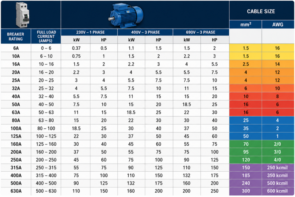
Choosing a motor cable by breaker rating sounds simple:
32 A breaker = 6 mm² cable
50 A breaker = 10 mm² cable
Sometimes that works. Sometimes it produces an undersized cable, nuisance tripping or a motor that struggles to accelerate.
Motor circuits are different from ordinary resistive-load circuits. The cable carries the normal motor current, while the circuit breaker may need to tolerate a starting current several times higher. The motor overload device and the short-circuit protective device may therefore have completely different ratings.
The tables below are useful for preliminary selection, but they are not a substitute for a complete cable calculation.
Safety warning: Cable and protection selection must follow the locally adopted electrical code, equipment instructions and installation conditions. An incorrect conductor or protective device can cause overheating, fire, electric shock or failure to disconnect a fault.
Quick IEC Cable Size Chart: Breaker Rating vs mm²
The following table assumes:
- Copper conductors
- PVC insulation rated for a 70°C conductor temperature
- Three loaded conductors
- Reference installation method C, such as a suitable cable fixed to a wall or installed on an appropriate tray
- Ambient air temperature of 30°C
- One circuit without grouping derating
- Breaker rated current not exceeding the cable’s reference current-carrying capacity
The ampacity figures come from the IEC 60364-5-52 simplified tables published in Schneider Electric’s Electrical Installation Guide. Different installation methods produce different values.
| Breaker rating | Minimum copper cable | Reference ampacity |
|---|---|---|
| 6 A | 1.5 mm² | 17 A |
| 10 A | 1.5 mm² | 17 A |
| 13 A | 1.5 mm² | 17 A |
| 16 A | 1.5 mm² | 17 A |
| 20 A | 2.5 mm² | 23 A |
| 25 A | 4 mm² | 31 A |
| 32 A | 6 mm² | 40 A |
| 40 A | 6 mm² | 40 A |
| 50 A | 10 mm² | 54 A |
| 63 A | 16 mm² | 73 A |
| 80 A | 25 mm² | 95 A |
| 100 A | 35 mm² | 117 A |
| 125 A | 50 mm² | 141 A |
| 160 A | 70 mm² | 179 A |
| 200 A | 95 mm² | 216 A |
| 225 A | 120 mm² | 249 A |
| 250 A | 150 mm² | 285 A |
| 315 A | 185 mm² | 324 A |
| 400 A | 240 mm² | 424 A |
This is not a universal motor-cable chart.
For example, 6 mm² has a reference capacity of 40 A under the stated conditions. Put the same cable inside an enclosed conduit, alongside several other loaded circuits or in a 40°C panel environment, and its usable capacity falls. IEC cable selection requires correction factors for ambient temperature, installation method and circuit grouping.
A 40 A breaker with 6 mm² cable leaves no spare capacity in this reference table. After even a small derating factor, 10 mm² may be required.
Quick US Copper Chart: Breaker Rating vs AWG
This second table is a general conductor reference, not a final motor-branch-circuit table.
It uses common 75°C copper conductor ampacities for not more than three current-carrying conductors under ordinary NEC Table 310.16 conditions. The 14, 12 and 10 AWG rows also reflect the normal small-conductor overcurrent limits of 15, 20 and 30 A.
| Breaker rating | Minimum copper conductor | 75°C reference ampacity |
|---|---|---|
| 15 A | 14 AWG | 20 A* |
| 20 A | 12 AWG | 25 A* |
| 30 A | 10 AWG | 35 A* |
| 40 A | 8 AWG | 50 A |
| 50 A | 8 AWG | 50 A |
| 60 A | 6 AWG | 65 A |
| 70 A | 4 AWG | 85 A |
| 80 A | 4 AWG | 85 A |
| 90 A | 3 AWG | 100 A |
| 100 A | 3 AWG | 100 A |
| 110 A | 2 AWG | 115 A |
| 125 A | 1 AWG | 130 A |
| 150 A | 1/0 AWG | 150 A |
| 175 A | 2/0 AWG | 175 A |
| 200 A | 3/0 AWG | 200 A |
| 225 A | 4/0 AWG | 230 A |
| 250 A | 250 kcmil | 255 A |
| 300 A | 350 kcmil | 310 A |
*Although the 75°C ampacity column shows higher values, the usual maximum overcurrent protection for 14, 12 and 10 AWG copper is 15, 20 and 30 A respectively, unless a specific code provision permits otherwise.
The NEC is revised on a three-year cycle, and the current published edition is the 2026 NEC. Actual enforcement depends on which edition has been adopted in the project’s jurisdiction.
Why Motor Breaker Size May Be Larger Than Cable Ampacity
This is the part that causes the most confusion.
For an ordinary load, you might expect a 100 A breaker to require a conductor with at least 100 A ampacity.
A motor branch circuit can be different because it usually has separate protection for:
- Overload protection, which protects the motor and circuit against sustained excessive current.
- Short-circuit and ground-fault protection, which clears high fault currents.
- The cable, which must carry the normal motor load and withstand the protective device’s operating time during a fault.
Under NEC motor rules, conductors for a single continuous-duty motor are generally sized at not less than 125% of the motor full-load current. The branch-circuit short-circuit and ground-fault device may be permitted at a much higher percentage so that normal starting current does not trip it.
For many common AC motors, NEC Table 430.52 permits an inverse-time circuit breaker rated up to 250% of motor full-load current, subject to the applicable conditions and exceptions.
That means this can be a valid motor-circuit arrangement:
Motor full-load current: 40 A
Minimum conductor ampacity: 40 × 1.25 = 50 A
Selected conductor: 8 AWG copper, 50 A at 75°C
Possible inverse-time breaker maximum: 40 × 2.5 = 100 A
At first glance, 8 AWG cable on a 100 A breaker looks wrong. In an ordinary circuit, it generally would be. In a properly designed motor branch circuit, the breaker is primarily providing short-circuit and ground-fault protection, while the overload device handles sustained overload current.
Do not apply this example to an IEC installation or a different motor type without checking the applicable rules.
mm² and AWG Are Not Exact Equivalents
Metric cable sizes and American Wire Gauge sizes are separate systems.
A 10 mm² conductor is not officially “7 AWG cable,” even though 7 AWG has a similar copper area. AWG sizes commonly used for power wiring also skip several of the closest mathematical equivalents.
| Metric size | Closest conductor area in AWG |
|---|---|
| 1.5 mm² | Approximately 15 AWG |
| 2.5 mm² | Approximately 13 AWG |
| 4 mm² | Approximately 11 AWG |
| 6 mm² | Approximately 9 AWG |
| 10 mm² | Approximately 7 AWG |
| 16 mm² | Approximately 5 AWG |
| 25 mm² | Approximately 3 AWG |
| 35 mm² | Approximately 2 AWG |
| 50 mm² | Approximately 1/0 AWG |
| 70 mm² | Approximately 2/0 AWG |
| 95 mm² | Between 3/0 and 4/0 AWG |
| 120 mm² | Approximately 250 kcmil |
| 150 mm² | Approximately 300 kcmil |
| 185 mm² | Approximately 350 kcmil |
| 240 mm² | Approximately 500 kcmil |
These are area comparisons only.
Do not replace a specified metric cable with the “nearest” AWG conductor without recalculating ampacity, termination compatibility, voltage drop and code compliance. A nominally similar copper area can have a different permitted ampacity because the insulation, installation method and governing standard are different.
How to Select a Motor Cable Correctly
A better approach is to size the circuit from the motor current—not by starting with the breaker.
1. Find the motor design current
Use the value required by the applicable standard.
Depending on the system, that could be:
- Motor nameplate current
- A code-table full-load current
- VFD rated input current
- VFD rated output current
- Manufacturer-specified minimum conductor ampacity
Do not calculate cable size from motor power alone when the actual current information is available.
Two motors with the same kilowatt rating can have different currents because of efficiency, power factor, voltage, pole count and design.
2. Apply the required motor-current multiplier
For NEC installations, a continuous-duty single-motor conductor is generally selected for at least 125% of the applicable full-load current.
For IEC-based designs, select a conductor whose corrected current-carrying capacity is at least equal to the design current, while coordinating the overload and short-circuit protective devices with the cable and starter. IEC 60364-5-52 provides the wiring-system selection and ampacity framework, most recently consolidated with its 2024 amendment.
3. Choose the installation method
The same cable size may have substantially different ampacity when installed:
- In thermal insulation
- Inside conduit
- In trunking
- Fixed directly to a wall
- On a perforated tray
- On a cable ladder
- Directly buried
- Inside an underground duct
- As separate single-core conductors
For three loaded copper conductors with PVC insulation, Schneider’s IEC-based reference table shows 1.5 mm² ratings ranging from approximately 13 A to 23 A depending on the installation method.
That is why a table saying “1.5 mm² equals 16 A” can be both correct and incorrect.
4. Apply temperature correction
IEC reference ampacities for cables in air are generally based on a 30°C ambient temperature.
For PVC insulation, Schneider’s IEC-based correction factors include:
| Ambient temperature | PVC correction factor |
|---|---|
| 30°C | 1.00 |
| 35°C | 0.94 |
| 40°C | 0.87 |
| 45°C | 0.79 |
| 50°C | 0.71 |
At 40°C, a cable with a reference capacity of 40 A is reduced to:
40 A × 0.87 = 34.8 AIt can no longer be treated as a 40 A cable under those conditions.
5. Apply grouping correction
Several loaded cables installed together heat one another.
For example, IEC-based grouping factors for cables touching in a group can reduce the usable ampacity to approximately:
- 80% for two grouped circuits
- 70% for three grouped circuits
- 65% for four grouped circuits
The precise factor depends on how the cables are arranged and supported.
A cable with a reference rating of 40 A could therefore become:
40 A × 0.87 temperature factor × 0.70 grouping factor
= 24.4 A corrected capacity
The cable did not physically become smaller. Its ability to lose heat became worse.
6. Check voltage drop
A cable may pass the ampacity calculation and still be too small because of voltage drop.
This is especially important for motors because starting current is commonly several times the normal full-load current. Schneider’s IEC guidance notes that direct motor starting current can be around five to seven times full-load current or higher, making starting voltage drop much more severe than normal running voltage drop.
Excessive voltage drop can cause:
- Slow acceleration
- Reduced starting torque
- Contactor dropout
- Motor overheating
- Overload trips
- VFD undervoltage faults
- Disturbance to other equipment
Long motor circuits often require a larger conductor than the thermal ampacity table suggests.
7. Verify short-circuit withstand
The conductor must survive the fault current until the breaker or fuse disconnects it.
This check depends on:
- Prospective short-circuit current
- Breaker clearing time
- Cable material
- Conductor cross-section
- Initial and final permitted temperatures
- Protective-device current-limiting performance
A breaker with the correct rated current is not automatically suitable. Its breaking capacity must also be at least equal to the prospective fault current at its installation point.
8. Coordinate the starter and protective devices
A typical direct-on-line starter may contain:
Circuit breaker or fuses
→ Contactor
→ Overload relay
→ Motor cable
→ Motor
The overload relay protects against sustained overload and phase-loss conditions, while the fuse or breaker provides short-circuit protection. Some motor-protection circuit breakers combine overload and short-circuit functions.
Motor starter manufacturers publish coordination tables that specify tested combinations of:
- Breaker or fuse
- Contactor
- Overload relay
- Motor rating
- Prospective short-circuit current
- Type 1 or Type 2 coordination
Use those tables instead of selecting each component independently and assuming they will cooperate.
Worked IEC Example
Suppose a 400 V motor has a nameplate current of 21 A.
The cable is:
- Copper
- PVC insulated
- Three loaded conductors
- Installed using reference method C
- In an ambient temperature of 40°C
- Not grouped with other circuits
From the reference table:
2.5 mm² = 23 A
4 mm²   = 31 A
Apply the 40°C PVC correction factor of 0.87:
2.5 mm²: 23 × 0.87 = 20.0 A
4 mm²:   31 × 0.87 = 27.0 A
The 2.5 mm² cable is insufficient because its corrected capacity is below the 21 A motor current.
The preliminary choice becomes:
4 mm² copperYou must still check:
- Cable length and voltage drop
- Starting method
- Breaker or fuse coordination
- Overload setting
- Short-circuit withstand
- Protective conductor size
- Manufacturer instructions
This example shows why choosing 2.5 mm² merely because “it is normally good for 20 or 25 A” is unreliable.
Worked NEC Example
Suppose a continuous-duty motor has an applicable full-load current of 28 A.
Minimum conductor ampacity:
28 A × 125% = 35 AFrom the 75°C copper ampacity table:
10 AWG = 35 AThe preliminary motor branch conductor is therefore 10 AWG copper, provided all terminal-temperature, adjustment and correction requirements are satisfied.
For a common AC motor using an inverse-time circuit breaker, the maximum initial breaker calculation may be:
28 A × 250% = 70 AThat does not mean every 28 A motor should automatically receive a 70 A breaker. The final device must comply with the applicable NEC provisions, standard sizes, equipment markings, starter ratings and any permitted increases needed for starting.
What About VFD-Supplied Motors?
Do not size a VFD installation from the motor breaker alone.
You may need to consider separately:
- Supply cable feeding the VFD
- Input breaker or fuses
- VFD rated input current
- Output cable from VFD to motor
- Motor full-load current
- Cable shielding and EMC requirements
- Maximum permitted motor-cable length
- Output reactor or sine-wave filter requirements
- VFD terminal temperature and conductor limits
NEC motor rules for power-conversion equipment can require output conductors to be sized from at least 125% of motor full-load current or from a larger minimum conductor size marked on the equipment.
Always use the drive manufacturer’s installation manual. The correct input breaker may be noticeably larger than the drive’s normal operating current.
Common Cable-Sizing Mistakes
Choosing the cable only from breaker current
This ignores motor starting, overload protection and code-specific motor rules.
Ignoring the installation method
A cable on an open ladder can carry more current than the same cable enclosed with several other circuits.
Forgetting ambient temperature
Inside an electrical panel, cable temperatures may be much higher than the surrounding room temperature.
Ignoring voltage drop
The cable may remain thermally safe while the motor receives too little voltage to start properly.
Treating mm² and AWG as interchangeable
Similar conductor area does not guarantee identical ampacity or code acceptance.
Using the overload setting as the breaker rating
The overload relay and short-circuit protective device perform different jobs.
Increasing the breaker after nuisance trips
A larger breaker may stop the nuisance trip while leaving the cable, contactor or starter inadequately protected. First determine whether the trip is caused by starting current, mechanical overload, incorrect settings or an actual fault.
Final Selection Checklist
Before approving a motor circuit, confirm:
[ ] Motor full-load current identified
[ ] Supply voltage and phase confirmed
[ ] Starting method considered
[ ] Required current multiplier applied
[ ] Cable material and insulation selected
[ ] Installation method identified
[ ] Ambient-temperature correction applied
[ ] Grouping correction applied
[ ] Terminal temperature ratings checked
[ ] Running voltage drop checked
[ ] Starting voltage drop checked
[ ] Short-circuit withstand verified
[ ] Breaker breaking capacity verified
[ ] Overload device selected and set correctly
[ ] Starter coordination table checked
[ ] Protective conductor sized
[ ] Local electrical code followed
Final Thoughts
There is no single cable size for every 32 A, 50 A or 100 A motor breaker.
The correct cable depends on the motor current and the conditions under which the cable must operate.
Use the breaker-versus-cable tables as a quick screening tool. Then calculate:
Motor current
→ Required conductor ampacity
→ Installation and temperature derating
→ Voltage drop
→ Short-circuit withstand
→ Breaker and overload coordination
The breaker number printed on the front is only one part of the calculation.
Sometimes, it is not even the number that determines the cable size.