A motor contactor that refuses to pull in can make a simple fault feel weirdly personal.
You press start. Nothing.
No click. No clunk. No motor. Just silence from the panel, while the operator looks at you like you should be able to fix it by staring harder.
The contactor is usually not the first part you should blame, though. It is only the visible actor. Behind it, there is a whole chain of control-circuit permissions: emergency stop, safety relay, stop button, start button, overload relay, PLC output, control voltage, fuses, terminals, selector switches, maybe a pressure switch, maybe a drive-ready signal, maybe some old auxiliary contact that has been quietly suffering since 2014.
So when a motor contactor is not pulling in, the real question is not only “is the contactor bad?”
The better question is:
Is the contactor coil actually receiving the correct voltage?
That one question can save a lot of time.
First, What Does “Not Pulling In” Mean?
A contactor “pulls in” when its coil is energized. The coil creates a magnetic field, pulls the armature closed, and the main power contacts close so the motor or load can run.
When it does not pull in, you may see one of these situations:
- The contactor does absolutely nothing
- The contactor hums but does not close
- The contactor pulls in and drops out immediately
- The contactor chatters rapidly
- The contactor only works sometimes
- The contactor pulls in manually, but not electrically
- The PLC output is on, but the contactor still does not energize
Each one points in a slightly different direction.
No sound at all usually means no coil voltage, wrong control path, open circuit, failed coil, or missing common/neutral/0V.
Humming or chattering often points toward low voltage, wrong coil voltage, AC coil issues, poor mechanical movement, dirt, damaged magnet surfaces, or unstable control power. ABB maintenance guidance also notes that a louder hum can happen if the shading coil in an AC contactor is broken, which can make the magnet chatter.
Pulls in then drops out? That often smells like a holding circuit, PLC latch, overload feedback, safety feedback, or unstable supply problem.
Lovely little puzzle.
Safety Before Testing the Contactor
A motor starter panel may contain 24V DC control wiring, 230V AC control wiring, and 400V three-phase motor power in the same cabinet.
So don’t treat the panel like a toy box.
Before testing:
- Follow lockout/tagout rules
- Know what voltage you are measuring
- Use a proper multimeter
- Use insulated tools
- Keep hands away from live power terminals
- Do not bypass safety circuits
- Do not force the contactor closed on a live machine
- Check the electrical drawing before disconnecting wires
Forcing a contactor in by hand is especially dangerous. The motor may start unexpectedly, and the load side may energize without the normal safety/control logic. Bad idea. Very bad.
You can inspect and test, yes. But don’t “help” the contactor close with your finger or screwdriver.
That’s not troubleshooting. That’s gambling.
1. Check the Coil Voltage Written on the Contactor
Before measuring anything, read the contactor coil label.
The coil voltage might be:
- 24V DC
- 24V AC
- 110V AC
- 120V AC
- 230V AC
- 400V AC
- Universal AC/DC coil, depending on model
Do not assume.
Two contactors can look almost identical from the front but have completely different coil voltages. Schneider Electric, for example, lists common contactor coil voltage codes such as BD = 24V DC and F7 = 110V AC 50/60Hz, so the code on the device matters.
If a 230V AC control circuit is connected to a 24V DC coil, the coil will not have a happy life. If a 24V DC circuit is connected to a 230V AC coil, the contactor probably won’t pull in at all.
Good check:
- Coil label matches the control circuit voltage
- AC/DC type matches the supply
- Replacement contactor has the same coil voltage as the old one
Bad check:
- Wrong coil voltage
- AC coil installed where DC coil is needed
- DC coil installed where AC coil is needed
- Replacement part selected only by contactor amp rating, not coil voltage
That last one happens often. Someone matches the current rating and frame size but forgets the coil.
The contactor fits perfectly.
Still doesn’t work.
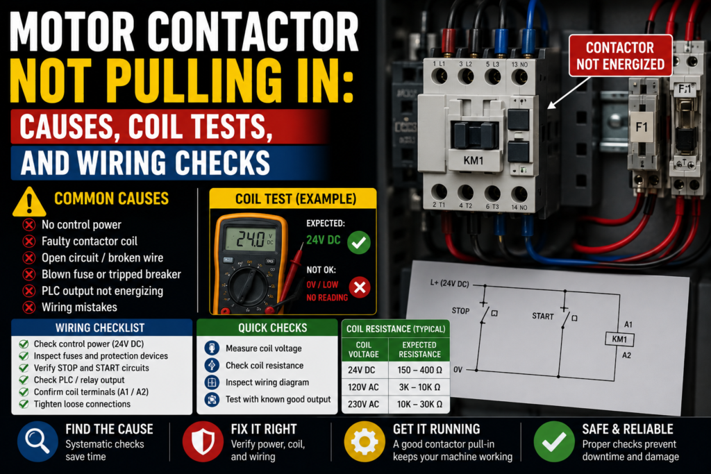
2. Measure Voltage at A1 and A2
The most important test is simple:
Measure the voltage directly at the contactor coil terminals, usually A1 and A2.
Do this when the machine is calling for the motor to start.
For example:
- Press the start button
- Give the PLC start command
- Run the machine in manual mode
- Activate the output from diagnostics, if safe and allowed
Then measure across A1 and A2.
You are checking whether the coil receives its proper operating voltage.
Good signs:
- Correct voltage appears across A1 and A2
- Contactor pulls in cleanly
- Voltage stays stable while energized
Bad signs:
- 0V at A1/A2
- Low voltage at A1/A2
- Voltage appears briefly then disappears
- Correct voltage is present but contactor does not pull in
- Voltage fluctuates or drops when the coil should energize
This test splits the fault into two big groups.
If there is no voltage at A1/A2
The contactor may be fine. The problem is upstream in the control circuit.
If correct voltage is present at A1/A2
The problem is likely the coil, contactor mechanism, wrong coil type, or mechanical binding.
Simple split. Very useful.
3. If There Is No Coil Voltage, Trace Backward
If you measure 0V at A1 and A2 when the contactor should energize, don’t replace the contactor yet.
Trace the control circuit backward.
The coil voltage may pass through several devices before reaching A1/A2:
- Control fuse or breaker
- Emergency stop circuit
- Safety relay output
- Stop button
- Start button
- Auto/manual selector
- PLC output
- Interposing relay
- Motor overload NC contact
- Pressure switch
- Limit switch
- Auxiliary contact
- Terminal blocks
- Neutral, common, or 0V return
One open contact anywhere in the chain can stop the coil.
A contactor cannot pull in if the control circuit is open. It’s not stubborn. It’s just not powered.
Manufacturer troubleshooting guides often point first to the control wiring and magnetic/coil system when a contactor does not close, which matches the practical field approach: prove the coil voltage, then trace the circuit.
4. Check the Control Fuse or Control Breaker
A blown control fuse can stop the contactor coil completely.
Check:
- Control circuit fuse
- MCB for control voltage
- Transformer secondary protection
- 24V DC output protection
- Fuse holder condition
- Loose fuse clips
- Burn marks
- Correct fuse rating
Good signs:
- Fuse has continuity
- Breaker is not tripped
- Voltage exists after the fuse
- Fuse holder is tight and clean
Bad signs:
- Fuse open
- Breaker tripped
- Voltage before fuse but not after
- Fuse blows again after replacement
- Burnt fuse holder
- Loose fuse connection
If the fuse blows again, do not keep replacing it.
Find the short or overload.
A repeated blown control fuse may be caused by:
- Shorted contactor coil
- Damaged cable
- Wrong coil voltage
- Shorted solenoid
- Faulty relay
- Crushed wire
- Moisture in connector
- Incorrect wiring after maintenance
Fuses are not decorations. They are trying to tell you something.
5. Check the Emergency Stop and Safety Relay
Many modern control circuits do not feed contactor coils directly through a simple start-stop circuit anymore.
The coil supply may pass through a safety relay or safety PLC output.
Check:
- Emergency stops released
- Guard doors closed
- Light curtains clear
- Safety relay powered
- Safety relay reset
- Safety output active
- Feedback loop healthy
- Safety PLC diagnostics, if used
If the safety relay output is off, the contactor coil may never receive voltage.
Good signs:
- Safety relay input channels healthy
- Safety reset accepted
- Safety outputs on
- No safety fault on HMI
Bad signs:
- E-stop pressed
- Guard door not detected
- Safety relay not resetting
- One channel missing
- Feedback loop open
- Safety output off
- Safety PLC blocking start
Do not bypass safety outputs to “test quickly.”
Check the proper diagnostic indicators and circuit drawings. A motor that starts with safety bypassed is not repaired. It is unsafe.
And unsafe machines have a nasty habit of becoming someone’s accident report.
6. Check the Stop Button
In a traditional motor control circuit, the stop button is usually normally closed.
That means it passes voltage when released and opens the circuit when pressed.
If the stop button contact is faulty, loose, or wired to the wrong contact block, the contactor coil circuit stays open.
Check:
- Stop button NC contact
- Voltage before and after the stop button
- Loose wires
- Broken terminal
- Damaged contact block
- Correct contact type
- PLC stop input, if PLC monitored
Good signs:
- Stop contact is closed when released
- Voltage passes through the stop circuit
- PLC sees stop condition as healthy
Bad signs:
- Stop contact open when released
- Wrong NO contact used instead of NC
- Loose wire on contact block
- Broken button mechanism
- Stop input stuck active
This is common after button replacement.
The button looks new. The wiring looks almost correct. But one small contact block mistake and the whole motor starter refuses to run.
Tiny plastic part, big headache.
7. Check the Start Button
The start button is usually normally open. It closes only while pressed.
If the start signal does not reach the control circuit or PLC, the contactor will not pull in.
Check:
- Start button NO contact
- Voltage before the button
- Voltage after the button when pressed
- PLC start input
- HMI start command, if touchscreen controlled
- Loose terminals
- Broken contact block
- Selector switch conditions
Good signs:
- Start input changes when pressed
- Voltage passes through when pressed
- Button returns correctly after release
Bad signs:
- No voltage feeding start button
- Start contact does not close
- PLC input does not change
- Button mechanically stuck
- Wrong contact block
- Wiring on wrong terminals
If the PLC sees the start button but the output does not turn on, the button is not the problem.
The PLC is probably blocking the motor because another condition is missing.
That is where the interlocks start their little circus.
8. Check the Motor Overload NC Contact
A motor overload relay usually has an auxiliary normally closed contact in the control circuit.
When the overload trips, that NC contact opens and prevents the contactor coil from energizing.
Check:
- Overload trip flag
- Reset button
- NC auxiliary contact
- Terminals 95-96 on many overloads, depending on model
- Overload setting
- Motor current
- Mechanical jam
- Phase loss
- Motor condition
Good signs:
- Overload not tripped
- NC contact closed
- Motor current setting correct
- Reset works properly
Bad signs:
- Overload tripped
- NC contact open
- Overload immediately trips again
- Wrong overload setting
- Motor hot
- Conveyor or pump jammed
- Phase missing
Do not just reset the overload and walk away.
Ask why it tripped.
Maybe the motor is overloaded. Maybe the conveyor is jammed. Maybe a bearing is stuck. Maybe the overload setting is wrong. Maybe one phase is missing.
Resetting without checking the cause is like muting a smoke alarm and calling it maintenance.
9. Check the PLC Output
On PLC-controlled machines, the contactor coil may be energized through a PLC output or an interposing relay controlled by the PLC.
Check:
- PLC output LED
- PLC output status in software
- Output terminal voltage
- Output common supply
- Output fuse
- Relay module
- Interposing relay coil
- Wiring from PLC to contactor
- PLC logic conditions
A common trap:
The PLC output LED is ON, but the contactor does not pull in.
That does not automatically mean the contactor is bad.
You still need to check whether voltage reaches the contactor coil.
Possible problems:
- Missing output common
- Blown output fuse
- Bad relay contact
- Broken wire
- Wrong terminal
- Failed output module
- Interposing relay not switching
- Coil return path missing
Good signs:
- PLC output turns ON
- Output voltage appears at terminal
- Relay energizes
- Voltage reaches A1/A2
Bad signs:
- PLC output ON but no voltage at coil
- PLC output OFF because interlock missing
- Output common missing
- Relay clicks but contact does not pass voltage
- Output module fault
Follow the signal:
PLC output → terminal → relay → safety/overload chain → A1/A2 coil.
Somewhere along that path, the voltage disappears.
Find that exact point.
10. Check the Neutral, Common, or 0V Return
People often measure only the “hot” side of the coil circuit.
But the return path matters just as much.
Depending on the control voltage, the coil needs a complete circuit:
- 24V DC: +24V and 0V
- 230V AC: live and neutral
- 110V AC: live and neutral/return
- Other control systems: according to wiring diagram
If A1 gets voltage but A2 has no proper return, the coil still will not energize.
Check:
- Neutral wire
- 0V common
- Terminal jumpers
- Broken return wire
- Loose terminal
- Shared common supply
- Control transformer secondary
- Grounded or floating control system design
Good signs:
- Correct voltage measured across A1 and A2
- Return path is continuous
- Common/neutral is present where expected
Bad signs:
- Voltage measured from A1 to ground, but not across A1/A2
- Missing neutral
- Broken 0V wire
- Loose common terminal
- Floating voltage reading
- Return jumper missing
This is an easy mistake.
You measure voltage from A1 to ground and think, “Coil has power.”
But the coil does not care about your meter to ground. It cares about voltage across its own terminals.
Measure across A1 and A2.
Always.
11. Test the Contactor Coil Resistance
If the correct voltage reaches A1/A2 but the contactor does not pull in, isolate power and test the coil resistance.
Power off first. Lockout if required. Disconnect at least one coil wire if necessary to avoid reading through other parts of the circuit.
Then measure resistance across the coil.
Good signs:
- Coil has a reasonable resistance reading
- Reading is stable
- No burnt smell
- No visible damage
Bad signs:
- Open circuit/infinite resistance
- Very low resistance compared with expected
- Burnt coil
- Cracked coil housing
- Coil gets hot quickly
- Coil smells cooked
The exact resistance depends on the contactor model and coil voltage. A small 24V DC coil will not read the same as a large 230V AC coil. So compare with the datasheet, a known-good contactor, or manufacturer information.
What you are mostly looking for:
- Open coil: broken winding, contactor will not energize
- Shorted coil: may blow fuses, overload the supply, or get hot
- Wrong coil: resistance may not match expected type/voltage
A coil can fail electrically while the rest of the contactor looks perfect.
Electrical parts have that talent. Very rude.
12. Check for Wrong Coil Type: AC vs DC
AC and DC coils are not always interchangeable.
A DC control circuit needs a DC coil unless the contactor has a universal coil designed for AC/DC operation.
An AC control circuit needs the correct AC coil voltage and frequency.
If the wrong coil type is installed, the contactor may:
- Not pull in
- Hum loudly
- Overheat
- Chatter
- Blow the control fuse
- Pull in weakly
- Fail early
Check the label carefully.
Good signs:
- Coil type matches supply type
- Coil voltage matches drawing
- Replacement coil matches original
- Coil code matches expected part
Bad signs:
- AC coil on DC supply
- DC coil on AC supply
- Wrong voltage range
- Unknown replacement part
- Coil label does not match drawing
This often happens when contactors are replaced from spare parts.
The frame size and current rating look right, so it gets installed. Then the machine won’t start because the coil is wrong.
Motor contactors are selected by both power rating and coil/control voltage.
Not one or the other.
Both.
13. Check for Low Coil Voltage
Sometimes the contactor receives voltage, but not enough.
Low coil voltage can make the contactor hum, chatter, pull in weakly, or drop out when the motor starts.
Check voltage across A1/A2 while the coil is energized or trying to energize.
Possible causes of low coil voltage:
- Weak 24V DC power supply
- Undersized transformer
- Long voltage drop in wiring
- Loose terminals
- Bad relay contacts
- Corroded terminals
- Overloaded control circuit
- AC supply problem
- Poor neutral/common connection
Good signs:
- Voltage stays near the coil rated value
- No large drop during start
- Contactor closes firmly
Bad signs:
- Voltage drops when start is pressed
- Contactor buzzes
- Contactor chatters
- Coil pulls in then drops out
- Control supply dips when other devices energize
If several contactors or solenoids energize at once, a weak control supply may sag. The contactor then drops out, the voltage recovers, it tries again, drops again. Click-click-click-click.
Not music.
A fault.
14. Check Mechanical Movement of the Contactor
If correct coil voltage is present and the coil tests OK, inspect the contactor mechanically.
With power off, check:
- Armature movement
- Dirt or debris
- Broken spring
- Melted plastic
- Mechanical jam
- Damaged contactor body
- Sticking auxiliary block
- Foreign objects
- Rust or corrosion
- Heat damage
The contactor should move freely.
If it feels stuck, rough, or jammed, it may not pull in even with a good coil.
Good signs:
- Smooth movement
- No cracks
- No burnt plastic
- No debris
- Armature returns normally
Bad signs:
- Mechanism stuck
- Contactor body melted
- Spring damaged
- Armature does not return
- Auxiliary block binding
- Dirt inside
- Signs of overheating
Do not file, bend, or “repair” contactor internals unless the manufacturer specifically allows maintenance for that model.
In many cases, a mechanically damaged contactor should be replaced.
Some parts are not worth hero surgery.
15. Check Auxiliary Contacts and Holding Circuit
In a classic start-stop circuit, the contactor uses an auxiliary contact to hold itself energized after the start button is released.
If the contactor pulls in only while the start button is held, then drops out immediately, check the holding circuit.
Check:
- Contactor NO auxiliary contact
- Wiring around the start button
- Stop button
- Overload NC contact
- Control fuse
- PLC latch bit, if PLC controlled
- Interposing relay
- Loose terminals
Good signs:
- Auxiliary contact closes when contactor pulls in
- Holding voltage remains after start button release
- PLC run latch stays on
Bad signs:
- Contactor drops when start is released
- Auxiliary contact not closing
- Wrong auxiliary contact used
- Holding wire broken
- PLC removes output immediately
- Overload contact opens
- Safety relay drops out
In PLC systems, the “holding circuit” may be software logic. The PLC may turn on the output for one second, then turn it off because feedback is missing.
So check the feedback signals too.
The contactor may pull in, but if the PLC does not see the auxiliary feedback, it may declare a fault and drop the output.
16. Check Contactor Feedback to PLC or Safety Relay
Many machines monitor whether a contactor actually changed state.
This can be done using:
- NO auxiliary contact
- NC auxiliary contact
- Mirror contact
- Safety feedback loop
- PLC digital input
- Drive enable feedback
- Motor running feedback
If feedback is missing or incorrect, the PLC or safety relay may block the contactor from energizing again.
Check:
- Feedback contact wiring
- Auxiliary contact operation
- PLC input status
- Safety relay EDM loop
- Contact welded detection
- Correct NO/NC contact type
- Terminal numbers
Good signs:
- Feedback changes when contactor moves
- PLC sees correct state
- Safety relay feedback loop healthy
Bad signs:
- Feedback stuck open
- Feedback stuck closed
- Wrong auxiliary contact installed
- Safety relay refuses reset
- PLC alarm says contactor feedback fault
This can be confusing.
The problem may not be the coil circuit directly. The machine may be refusing to energize the coil because it does not trust the contactor feedback.
That’s very common in safer machine designs.
17. Check Wiring and Terminals
Loose wiring can create every possible contactor symptom.
No pull-in. Chattering. Random dropouts. Works when the cabinet door is open but fails when closed. Works on day shift but not night shift because the machine vibrates differently. Great fun.
Check:
- A1/A2 terminals
- Control circuit terminals
- Overload auxiliary terminals
- PLC output terminal
- Relay socket
- Fuse holder
- Neutral/0V terminals
- Terminal jumpers
- Wire numbers
- M12 or field connectors
- Cable damage near moving parts
Look for:
- Loose screws
- Burn marks
- Discoloration
- Broken ferrules
- Crushed insulation
- Corrosion
- Oil contamination
- Melted plastic
- Wires barely inserted
Gently tug suspicious wires.
Not like you’re pulling a tree root. Just enough to see if the wire is actually clamped.
Bad connections often heat up, oxidize, and become worse over time. A contact that was “almost okay” last month may be open today.
18. Check If the Contactor Is Being Blocked by Interlocks
Sometimes nothing is electrically broken.
The machine simply does not allow the contactor to energize because one condition is missing.
Common interlocks:
- Guard door closed
- Emergency stop released
- Air pressure OK
- Overload reset
- Drive ready
- Motor protection OK
- Conveyor clear
- Product present
- Temperature reached
- Manual/auto mode selected
- Home position reached
- Safety relay active
- No active alarms
- Communication OK
In PLC-controlled systems, check the motor start permissive logic.
The start button may be seen by the PLC, but the output remains off because one bit is missing.
Good signs:
- All permissives true
- Motor start command reaches output
- No alarms or blocks active
Bad signs:
- Start command received but output blocked
- Missing ready signal
- Active alarm
- Mode not correct
- Safety or overload not healthy
This is why HMI diagnostic pages are so useful.
A good HMI will show “Motor blocked: overload tripped” or “Motor blocked: safety not reset.”
A bad HMI will just sit there saying “Fault.”
Helpful as a chocolate screwdriver.
Quick Checklist: Motor Contactor Not Pulling In
Use this order when troubleshooting.
- Read the coil label
- Voltage correct?
- AC or DC correct?
- Replacement part correct?
- Measure A1/A2 voltage
- Correct voltage when start is requested?
- Stable voltage?
- Voltage drops?
- If no coil voltage, trace backward
- Fuse
- Stop button
- Start button
- Safety relay
- PLC output
- Overload NC contact
- Selector switch
- Interlocks
- Check control power
- 24V DC supply
- Control transformer
- Neutral/0V return
- Breakers and fuses
- Check safety circuit
- E-stops released
- Guards closed
- Safety relay reset
- Feedback loop healthy
- Check overload relay
- Not tripped
- NC contact closed
- Correct setting
- Motor/load not jammed
- Check PLC output
- Output command ON
- Output terminal voltage
- Output common present
- Interposing relay working
- Check coil resistance
- Not open circuit
- Not shorted
- Compare with known-good/datasheet
- Check mechanical movement
- Not stuck
- No melted body
- No dirt/debris
- Armature moves freely
- Check holding circuit
- Auxiliary contact works
- Coil stays energized
- PLC latch remains true
- Check feedback
- PLC sees contactor state
- Safety relay EDM loop OK
- Correct NO/NC auxiliary contact
- Check wiring
- Loose terminals
- Broken wires
- Missing jumpers
- Burn marks
- Wrong terminal numbers
Good vs Bad Test Results
| Test Point | Good Result | Bad Result |
|---|---|---|
| Coil label | Matches control voltage and AC/DC type | Wrong voltage or wrong coil type |
| A1/A2 voltage | Correct rated voltage during start command | 0V, low voltage, unstable voltage |
| Control fuse | Good continuity, voltage after fuse | Blown fuse, no voltage after fuse |
| Stop button | NC contact closed when released | Open contact when released |
| Start button | NO contact closes when pressed | No signal change |
| Safety relay | Outputs active after reset | Not reset, channel fault, output off |
| Overload relay | Not tripped, NC contact closed | Tripped, NC contact open |
| PLC output | Output ON and voltage present | Output ON but no voltage, or output OFF |
| Coil resistance | Reasonable stable reading | Open circuit or very low resistance |
| Mechanical movement | Smooth pull-in and return | Stuck, melted, damaged, dirty |
| Holding circuit | Stays energized after start release | Drops out immediately |
| Feedback contact | Changes state correctly | Stuck, wrong type, PLC input missing |
Example: Contactor Does Nothing When Start Is Pressed
Let’s say a conveyor motor contactor does not pull in.
The operator presses start. Nothing happens.
You check the coil label. It says 230V AC.
You press start and measure across A1 and A2.
Result: 0V.
So the contactor is not proven bad. It is not even being powered.
Next, you trace the control circuit.
There is voltage after the control fuse. Good.
Voltage passes through the stop button. Good.
Safety relay output is active. Good.
Then you check the overload relay NC contact.
Open.
The overload is tripped.
You reset the overload, but before starting again, you check the motor and conveyor. The conveyor belt is jammed with product. That caused high motor current, which tripped the overload, which opened the contactor coil circuit.
Real cause: jammed conveyor.
Not bad contactor.
Not bad PLC.
Not bad start button.
The contactor was only refusing to pull in because the overload contact was doing its job.
Example: Correct Voltage at Coil, But Contactor Still Does Not Pull In
Now another case.
The contactor coil label says 24V DC.
You press start and measure 24V DC across A1 and A2.
But the contactor does not pull in.
Now you know the control circuit is probably giving the command. So you isolate power and test the coil resistance.
The coil reads open circuit.
That means the coil winding is broken. The contactor coil is faulty, or the contactor/coil assembly needs replacement depending on model.
This is one of the few times where replacing the contactor actually makes sense.
Because you proved it.
Not guessed it.
Example: Contactor Pulls In, Then Drops Out
A motor contactor pulls in for half a second, then drops out.
Possible checks:
- Does coil voltage disappear?
- Does the PLC output turn off?
- Does overload feedback open?
- Does safety relay drop?
- Does contactor auxiliary feedback reach the PLC?
- Is the holding circuit working?
- Is the 24V supply dipping?
- Is the motor causing overload immediately?
You measure A1/A2.
Voltage appears, then disappears.
Now check why.
PLC output turns off because the PLC does not receive contactor feedback within one second.
You inspect the auxiliary contact. It is installed, but wired to the wrong terminal.
So the PLC commands the contactor, the contactor pulls in, but the PLC never sees confirmation. Then it drops the output.
Again, the coil was not the real problem.
Feedback was.
Common Mistakes When Troubleshooting a Contactor
The first mistake is replacing the contactor before measuring coil voltage.
If A1/A2 has no voltage, the contactor may be perfectly fine.
The second mistake is measuring only from A1 to ground. Measure across A1 and A2. The coil needs voltage across its terminals.
The third mistake is ignoring the overload relay. A tripped overload often opens the coil circuit.
The fourth mistake is forgetting the coil voltage when replacing a contactor. Current rating is not enough. Coil voltage matters.
The fifth mistake is bypassing safety devices to “test.” Don’t do that.
The sixth mistake is assuming the PLC output LED means voltage reached the coil. It may not. A missing output common or bad relay contact can fool you.
The seventh mistake is not checking mechanical load. A motor contactor may be blocked by overload because the machine is mechanically jammed.
Electrical troubleshooting often ends outside the panel.
Funny, but true.
Final Thoughts
When a motor contactor is not pulling in, don’t start by blaming the contactor.
Start with the coil.
Read the coil label. Measure voltage across A1 and A2. If the voltage is missing, trace the control circuit backward through fuses, stop buttons, safety relays, overload contacts, PLC outputs, and interlocks. If correct voltage is present, then test the coil, check the mechanical movement, and inspect the contactor body.
That is the clean path.
Not random part swapping. Not guessing. Not pressing reset 14 times and hoping the machine forgives you.
A motor contactor needs three basic things:
Correct coil voltage.
Complete control circuit.
Free mechanical movement.
If one of those is missing, it will not pull in.
So follow the voltage, follow the wiring, and follow the logic.
The fault is usually sitting in the chain somewhere, waiting to be found.