While insulation testing checks the insulation between windings and frame, winding resistance testing checks the windings themselves — their continuity and their balance. Measuring the resistance of each winding and comparing the three reveals opens, shorts, and imbalances within the windings. Understanding this test complements insulation testing, together giving a thorough electrical assessment of the motor’s windings.
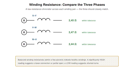
Figure 10.1 — Comparing winding resistances. Measure each winding pair with a low-resistance ohmmeter; the three should closely match. A high reading suggests a loose connection or partial open; a low reading suggests shorted turns.
Measuring winding resistance
Winding resistance is measured with an ohmmeter across the windings, ideally a low-resistance ohmmeter since motor windings often have low resistance that an ordinary meter measures imprecisely. On a safely isolated motor, the resistance across each winding (or each pair of terminals, depending on the connection) is measured, giving three readings for the three windings. The key comparison is among the three: healthy windings have closely matching resistances, because they are made alike. Significant differences between the three readings indicate a problem in the winding that differs. The measurement must be done carefully, as the resistances are low and lead resistance and contact quality can affect the reading, which is why a proper low-resistance measurement is preferred for accuracy. Understanding how to measure winding resistance — across each winding on an isolated motor, with a suitable ohmmeter, comparing the three — is the basis for using it to assess the windings. The comparison among the three phases is the heart of the test: since the windings should match, any significant mismatch points to a fault in the odd winding, making the balance of the three resistances the key diagnostic.
Interpreting winding resistance
Interpreting the winding resistances centers on their balance and their magnitude. Three closely matching resistances indicate healthy, balanced windings. A significantly higher resistance in one winding indicates a problem adding resistance — a loose or corroded connection, or a partial open in the winding — because the extra resistance raises that winding’s reading. A significantly lower resistance in one winding can indicate shorted turns, where part of the winding is bypassed, reducing its resistance. So a high reading points to a connection or open problem, and a low reading to a short, with the healthy state being three matched readings. An infinite reading (no continuity) indicates a completely open winding or connection. Understanding these interpretations — matched is healthy, high is a connection or open, low is a short, infinite is an open — lets you diagnose winding problems from the resistance measurements. Combined with the insulation test (winding to frame) and the balance checks (voltage and current in operation), winding resistance testing (winding continuity and balance) completes the electrical assessment, and interpreting the three readings’ balance and magnitude reveals the winding faults — opens, shorts, and bad connections — that affect the motor’s operation.
Putting the electrical tests together
The three electrical tests — balance (voltage and current in operation), insulation resistance (winding to frame), and winding resistance (the windings themselves) — together give a thorough assessment of a motor’s electrical condition, and using them in combination is more powerful than any one alone. The balance checks, done with the motor running, reveal supply imbalances and operating current problems. The insulation test, done on an isolated motor, reveals insulation degradation and ground-fault risk. The winding resistance test, also on an isolated motor, reveals winding opens, shorts, and connection problems. Together they cover the motor’s insulation, its windings, and its operating balance, so that a thorough electrical check applies all three as appropriate. In troubleshooting, the choice of tests follows the symptom: a ground fault calls for insulation testing, a suspected winding fault for winding resistance and balance, an overheating or imbalance complaint for balance checks. Understanding how the tests complement each other — each assessing a different aspect of the motor’s electrical health — lets you assemble a complete electrical picture, applying the right tests for the situation and combining their results to localize a fault to the insulation, the windings, or the supply, which is the essence of electrical motor diagnosis.
What resistance imbalance reveals
The power of the winding resistance test lies in what an imbalance among the three windings reveals, and understanding this makes the test a precise diagnostic. Since the three windings are manufactured to be alike, they should have nearly equal resistances, so any significant difference points specifically to a problem in the winding that differs, localizing the fault to one phase. A high resistance in one winding means something has added resistance to it — most often a loose, corroded, or poor connection somewhere in that phase, or a partial break in the winding — because a good connection and intact winding have low resistance, and extra resistance signals a connection or continuity problem. A low resistance in one winding means part of it is being bypassed — shorted turns, where a short circuit between turns of the winding reduces its effective length and resistance. So the imbalance not only detects a fault but indicates its nature: high points to a connection or partial open, low to shorted turns. Understanding what the imbalance reveals — which winding is faulty and, by the direction of the imbalance, what kind of fault — makes the winding resistance test a precise tool that both localizes a winding fault to one phase and characterizes it, guiding the specific repair, whether tightening a connection, repairing an open, or addressing a shorted winding.
Scenario: the high-resistance phase
A scenario shows winding resistance testing localizing a fault. A motor was running weak and its currents were imbalanced, suggesting a problem in one phase. With the motor safely isolated, the winding resistances were measured, and one phase read noticeably higher than the other two, which matched each other. Understanding that a high winding resistance indicates added resistance — a poor connection or partial open — localized the fault to that phase and pointed to a connection problem. Investigating that phase’s connections revealed a loose, corroded terminal adding resistance, which reduced the current in that phase (causing the imbalance) and weakened the motor. Cleaning and tightening the connection restored the winding resistance to match the others, balanced the currents, and returned the motor to full strength. This scenario shows the winding resistance test localizing and characterizing a fault: the high reading in one phase pointed to a connection problem in that specific phase, which inspection confirmed and fixed. It reinforces that comparing the three winding resistances localizes a fault to the odd phase, and that a high reading indicates a connection or open problem, guiding the diagnosis straight to the affected phase and the nature of its fault — here a loose connection — which the balanced-resistance principle of the test revealed precisely.
Combining winding resistance with the other tests
Winding resistance testing is most powerful combined with the other electrical tests, and understanding how they fit together completes the electrical diagnosis. Winding resistance checks the windings’ continuity and balance (opens, shorts, connections); insulation resistance checks the winding-to-frame insulation (ground faults, insulation degradation); and the running balance checks the operating voltages and currents (supply and operating problems). Together they cover the motor’s electrical condition comprehensively: the windings themselves, their insulation to ground, and their operating balance. In a thorough electrical assessment, all three are applied as appropriate, and their combined results localize a fault — a winding open or short (winding resistance), a ground fault or insulation problem (insulation test), or a supply or operating imbalance (running balance). Understanding how the tests combine — each assessing a different aspect, together giving the complete electrical picture — lets you assemble a full diagnosis rather than relying on any single test. It reinforces that the electrical tests are complementary: winding resistance for the windings’ continuity, insulation resistance for their insulation, and running balance for their operation, and combining them — choosing the relevant tests for the symptom and interpreting them together — is what provides a complete electrical assessment of the motor, localizing faults across the windings, insulation, and supply that no single test could fully diagnose alone.
Completing the electrical picture
Winding resistance testing completes the electrical picture of the motor, and understanding its place among the tests shows how a full electrical assessment is assembled. The running balance checks operation, the insulation test checks the winding-to-frame insulation, and the winding resistance test checks the windings themselves — their continuity, balance, and internal condition. This last test fills in the picture of the windings as conductors: are they continuous, balanced, and free of opens and shorts? Together with the other tests, it gives a complete electrical assessment covering operation, insulation, and the windings’ condition. So winding resistance testing is the piece that examines the windings’ own electrical integrity, completing the assessment that the other tests begin. Understanding its place — completing the electrical picture by checking the windings themselves — shows how the tests together form a full electrical diagnosis. It reinforces that a thorough electrical assessment uses all the tests, each contributing its part: operation (balance), insulation (megger), and winding integrity (resistance), together completing the picture. Winding resistance testing’s contribution — the windings’ continuity and balance — is essential to that complete picture, so that understanding its role alongside the other tests lets you assemble a full electrical assessment of the motor, examining its operation, its insulation, and its winding integrity to localize any electrical fault, which is the goal of comprehensive electrical motor diagnosis that the combination of tests achieves.
Accounting for temperature
A practical refinement in winding resistance testing: winding resistance varies with temperature, so account for temperature when comparing readings, especially against past values or specifications. Copper’s resistance rises with temperature, so a winding measured hot reads higher than the same winding measured cold. When comparing the three windings to each other at the same temperature, this does not matter (they are all at the same temperature). But when comparing to past readings or specifications taken at a different temperature, the temperature difference must be accounted for, or a temperature-related difference could be mistaken for a fault. Understanding that winding resistance varies with temperature refines the test’s interpretation: the three-phase comparison at one temperature is unaffected, but comparisons across temperatures need adjustment. It reinforces careful interpretation of winding resistance: the balance among the three phases (at one temperature) is the primary diagnostic and is temperature-independent, but comparing absolute values across temperatures requires accounting for the temperature effect on copper resistance. This refinement — account for temperature when comparing winding resistances across different temperatures — ensures the test is interpreted correctly, distinguishing genuine faults from temperature-related differences, which matters when comparing readings to past baselines or specifications taken at different temperatures, though not when comparing the three phases to each other at the same temperature, which is the primary use of the test.