
The regions just outside the 4–20 mA range are used for diagnostics, and standards define how transmitters use them to signal faults. Understanding these diagnostic currents — especially the NAMUR NE 43 conventions and burnout behavior — lets you interpret currents at the edges correctly and take advantage of the loop’s built-in fault reporting.
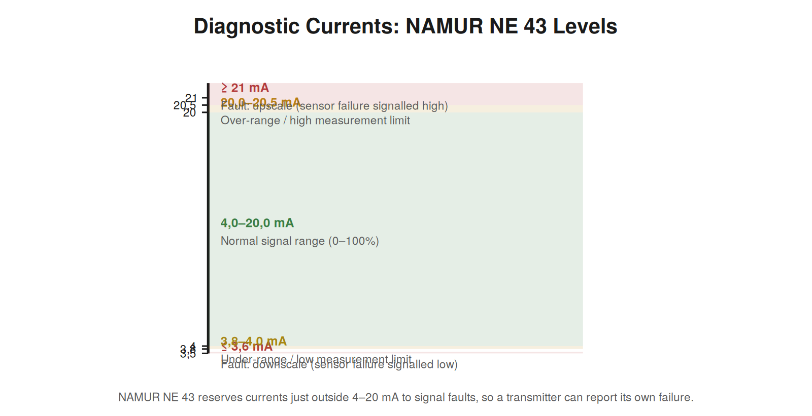
NAMUR NE 43 levels
The NAMUR NE 43 recommendation standardizes how the current range is used, reserving specific regions for measurement and for fault signaling. Within the range, it allows a little margin for over- and under-range: the measurement can run slightly below 4 mA (down to about 3,8 mA) and slightly above 20 mA (up to about 20,5 mA) to represent minor out-of-range conditions without triggering a fault indication. Beyond these, currents at or below about 3,6 mA and at or above about 21 mA are reserved to signal transmitter faults — the transmitter driving the current to these levels to report that it has detected a failure in itself. Understanding these levels lets you interpret an edge current correctly: a current of 3,9 mA is a slight under-range measurement, while 3,5 mA is a fault signal, and the distinction matters. Reading a current against the NAMUR levels tells you whether it represents a measurement (even a slightly out-of-range one) or a signaled fault, which directs your response appropriately.
Upscale and downscale burnout
Burnout refers to the direction a transmitter drives its current when it detects a fault: upscale burnout drives the current high (above 20 mA), and downscale burnout drives it low (below 4 mA). The choice of direction is a configuration decision with safety implications, because it determines how the control system sees a transmitter fault — as a high reading or a low reading — and which is safer depends on the application. For a measurement where a false high reading would trigger a safe response (like a high-level alarm shutting off a fill), upscale burnout may be chosen so a fault reads high and triggers the safe action; for others, downscale is safer. Understanding burnout direction is important both for interpreting a fault current (an out-of-range current in the burnout direction is the transmitter reporting itself failed) and for knowing that the direction is a deliberate, safety-relevant setting. When you see a current in a burnout region, recognizing it as the transmitter’s self-reported fault — in its configured burnout direction — correctly directs you to the transmitter’s own diagnostics rather than to a process explanation.
Using diagnostics in troubleshooting
The diagnostic currents are a gift to troubleshooting, because they let the loop itself tell you when the transmitter has failed, before you investigate anything else. A current in a burnout region immediately indicates a transmitter-detected fault, pointing you straight at the transmitter and its diagnostics rather than at the wiring or process. This is faster and more specific than having to deduce a transmitter fault indirectly. Reading the current against the diagnostic levels — recognizing burnout currents as self-reported transmitter faults, and the small over/under-range allowances as still-valid measurements — extracts the built-in diagnostic information the loop provides. Combined with the fault-signature reading covered earlier, the NAMUR levels refine your interpretation of edge currents, distinguishing a genuine near-limit measurement from a signaled fault. This built-in fault reporting, understood and used, makes the modern 4–20 mA loop partly self-diagnosing, and reading its diagnostic currents is part of troubleshooting it efficiently.
Configuring burnout for safety
The choice of burnout direction — upscale or downscale — is a safety-relevant configuration decision, and understanding the reasoning helps you interpret and set it correctly. The principle is that a transmitter fault should drive the current in the direction that causes the safe response for that particular measurement. Consider a high-level shutdown: if a transmitter fault drives the level reading high (upscale burnout), the system sees an apparent high level and triggers the shutdown — a safe response, since a failed level sensor errs toward stopping a fill. But for a different measurement, the safe direction might be downscale. So burnout direction is chosen per application to make a sensor failure fail safe, and it is typically set to match the safety logic of the specific measurement. Understanding this tells you two things: when you see a burnout current, it is the transmitter reporting a fault in its configured direction; and when configuring a transmitter, the burnout direction should be chosen deliberately so that a failure produces the safe outcome. This makes burnout not just a diagnostic feature but part of the safety design of a measurement.
Scenario: the burnout current that meant a failed sensor
A scenario shows a diagnostic current at work. A temperature loop suddenly read above 21 mA — outside the normal range, in the upscale burnout region. An operator might have thought the temperature had spiked dangerously high, but reading the current against the NAMUR levels showed it was in the burnout region, not a valid over-range measurement: the transmitter was signaling a fault in itself, not reporting a real high temperature. The transmitter, having detected a failure of its own sensor, drove the current upscale by its configured burnout direction to announce the fault. Recognizing the burnout signature directed the response correctly — to the transmitter and its failed sensor — rather than to a nonexistent temperature excursion. Investigation found the sensor had failed, the transmitter had correctly detected and signaled it via burnout, and replacing the sensor restored normal operation. This scenario shows the diagnostic value of burnout currents: the transmitter told the system it had failed, by driving the current into the burnout region, and reading that signature correctly — as a self-reported fault, not a process extreme — led straight to the real problem, a failed sensor, rather than a false alarm about the process.
The value of self-diagnosing transmitters
Burnout signaling makes a transmitter partly self-diagnosing, and appreciating this capability shapes how you troubleshoot modern loops. A transmitter that can detect a fault in itself and signal it by driving the current to a burnout region is telling you, through the loop, that it has failed — no deduction required. This is a significant advance over a simple transmitter that just outputs a current with no self-check: the self-diagnosing transmitter announces its own failure, directing you straight to it. When troubleshooting a modern loop, checking for a burnout current early is worthwhile, because if present, it immediately identifies a transmitter fault and saves the effort of investigating the wiring, power, or process. The transmitter’s self-diagnosis, read from the burnout current, is a shortcut to identifying transmitter faults. Combined with HART’s richer self-diagnostics, modern transmitters can report their own health in ways that greatly speed troubleshooting, and reading these self-reports — burnout currents and HART diagnostics — is part of troubleshooting modern loops efficiently. The transmitter increasingly helps diagnose itself, and taking advantage of that self-diagnosis, rather than ignoring it, is a mark of up-to-date loop troubleshooting.
The loop’s built-in intelligence
The diagnostic currents represent a kind of built-in intelligence in the modern loop, and appreciating this shapes a modern approach to loop work. Where an early current loop simply carried a measurement, the modern loop — with NAMUR diagnostic levels, burnout signaling, and often HART — carries diagnostic information too: it can report faults, signal a failed transmitter, and (via HART) provide detailed self-diagnostics. This built-in intelligence means the modern loop participates in its own diagnosis, telling you when something is wrong rather than merely carrying a measurement passively. A modern approach to loop work takes advantage of this: reading the diagnostic currents and HART data to let the loop report its own faults, rather than treating the loop as a passive circuit to be probed entirely from outside. The loop’s built-in intelligence is a resource, and using it — reading burnout currents, NAMUR levels, HART diagnostics — makes troubleshooting faster by letting the loop tell you what it can about its own condition. Appreciating that the modern loop has this diagnostic intelligence, and learning to read what it reports, is part of troubleshooting modern loops well, complementing the analog reasoning with the loop’s own self-diagnosis for a fuller and faster picture of any fault.
Reading edge currents correctly
A specific skill the diagnostic levels demand is reading edge currents correctly — distinguishing a slightly out-of-range measurement from a burnout fault signal, since both are near the edges of the range. A current at 3,9 mA is a slight under-range measurement, still valid, within the NAMUR measurement allowance; a current at 3,5 mA is a downscale burnout fault signal. Similarly, 20,3 mA is a slight over-range measurement, while 21,5 mA is an upscale burnout fault. The distinction is the level: within the measurement allowance (roughly 3,8 to 20,5) is a valid, if slightly out-of-range, measurement; beyond it (below 3,6 or above 21) is a fault signal. Reading an edge current correctly means checking which region it falls in — measurement allowance or fault region — and interpreting accordingly: a valid measurement to be taken as such, or a fault signal to direct you to the transmitter. Getting this right matters, because treating a fault signal as a measurement (or vice versa) misinterprets the loop: a burnout fault read as a real extreme measurement would cause a false process response, while a valid slight over-range read as a fault would prompt an unnecessary investigation. Reading edge currents against the NAMUR levels — measurement or fault — interprets them correctly, which is essential where the current sits near the boundaries of the normal range.
Diagnostics as part of modern competence
Understanding and using the loop’s diagnostic features — NAMUR levels, burnout signaling, and the transmitter self-diagnostics they enable — is part of modern loop competence, distinguishing up-to-date practice from a purely traditional analog approach. The modern loop offers diagnostic information beyond the basic measurement, and a competent modern technician reads and uses it: interpreting burnout currents as self-reported faults, distinguishing diagnostic currents from measurements via the NAMUR levels, and taking advantage of the loop’s self-diagnosis to speed troubleshooting. This is part of what it means to work competently with modern loops, which are more capable and self-diagnosing than early loops. A technician who ignores the diagnostic features troubleshoots modern loops as if they were basic ones, missing the self-diagnostic information available; one who uses them troubleshoots more efficiently, letting the loop help diagnose itself. Understanding the diagnostic currents and burnout, and using them in troubleshooting, is thus part of modern loop competence, keeping your practice up to date with the capabilities modern loops provide. As loops have grown more capable — with diagnostics and, via HART, rich self-reporting — competent practice has grown to use these capabilities, and understanding the diagnostic currents is part of the modern skill set that makes the most of what today’s loops offer for efficient, informed troubleshooting.