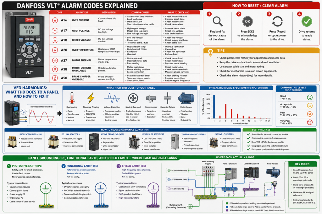
A control panel may contain several connections that all appear to mean “ground”:
PE
FE
Chassis
Shield
0 V
COM
Earth
They are not interchangeable.
Connecting every green terminal to one random screw may allow the machine to run, but it can also create electrical-shock risk, unstable analog signals, communication faults and VFD interference.
The practical distinction is:
- Protective Earth (PE) protects people when insulation fails.
- Functional Earth (FE) helps equipment operate correctly, particularly for EMC and signal reference.
- Cable-shield termination provides a low-impedance path for electromagnetic interference.
- 0 V or signal common is part of the control circuit and is not automatically earth.
- Neutral is a current-carrying supply conductor and is not a substitute for PE.
IEC 60204-1 covers protective bonding and EMC requirements for machine electrical equipment, while IEC 60364-5-54 covers earthing arrangements and protective conductors in low-voltage installations.
Safety warning: Grounding and protective bonding are safety-critical. Conductor sizes, test requirements and bonding arrangements must follow the locally adopted standards, equipment manuals and panel-assessment requirements.
Quick Answer: Where Each Connection Lands
| Connection | Main purpose | Where it normally lands |
|---|---|---|
| Incoming supply PE | Electric-shock protection | Main PE terminal or PE busbar |
| Cabinet frame | Protective bonding | Main PE bar |
| Mounting plate | Protective bonding and EMC reference | Cabinet frame/PE system with broad conductive contact |
| Door | Protective bonding | Frame or PE bar through a bonding conductor or braid |
| DIN rail carrying PE terminals | Protective bonding | PE bar or bonded mounting plate |
| Device PE terminal | Electric-shock protection | PE terminal block or PE bar |
| Device FE terminal | EMC or functional reference | FE rail, conductive DIN rail or mounting plate as specified |
| Cable shield | EMC interference control | Shield clamp, EMC bar, chassis or connector shell |
| VFD motor-cable shield | High-frequency return path | 360° termination at drive and motor ends |
| Motor PE conductor | Electric-shock protection | Drive PE/PE bar and motor frame |
| 24 V DC 0 V | Control-circuit return | 0 V distribution terminals |
| Neutral N | AC load-current return | Neutral bar—not PE or shield bar |
This table describes a typical industrial panel. The device manufacturer’s wiring instructions take priority where they specify a particular arrangement.
1. Protective Earth: PE
Protective Earth exists primarily to protect people.
If a phase conductor touches an exposed metal enclosure, PE provides a low-impedance fault path so that the fuse, breaker or other protective device disconnects the supply.
Typical PE-connected parts include:
- Control-panel enclosure
- Mounting plate
- Metal door
- Cable-gland plates
- Motor frames
- VFD and servo-drive PE terminals
- Transformer frames
- Power-supply chassis
- Metal operator stations
- Metal junction boxes
- Conductive machine structures
- DIN rails used as part of an approved PE system
PE is not intended to carry normal load current. It may carry leakage and fault current, especially where drives and EMC filters are installed, but it must never be used as a substitute for neutral or 0 V. Schneider defines PE as the connection intended to reduce electric-shock risk by keeping exposed conductive surfaces at earth potential.
Where the incoming PE lands
The incoming protective conductor should normally land first on a clearly identified main PE terminal or busbar near the panel’s supply entry:
Incoming PE
     │
     ▼
Main PE terminal or busbar
     ├── Cabinet frame
     ├── Mounting plate
     ├── Door bonding conductor
     ├── VFD PE
     ├── Transformer frame
     ├── Motor PE terminals
     └── Outgoing field-circuit PE terminals
The incoming conductor should not pass through an ordinary disconnect, fuse or control device before reaching the protective bonding system.
Do not land the incoming PE on a painted mounting-plate screw and then assume the entire cabinet is bonded.
Bond the mounting plate properly
A metal mounting plate can provide both protective bonding and a useful EMC reference plane, but only when it has reliable electrical contact with the enclosure and PE system.
Paint, powder coating, anodising and corrosion can isolate one metal part from another.
Use:
- Manufacturer-provided bonding studs
- Approved serrated washers
- Bare-metal contact areas
- Short bonding conductors
- Wide braided straps where high-frequency bonding matters
- Corrosion protection suitable for the environment
Schneider recommends metal-to-metal contact between enclosure parts and removal of paint or other insulating material at bonding locations.
The door needs bonding too
Do not automatically treat hinges as a reliable protective connection.
Paint, grease, corrosion, replaceable hinge pins and mechanical wear can increase hinge resistance. Doors carrying HMIs, pushbuttons, sockets, lamps or other electrical equipment should have a deliberate bonding connection.
A short flexible copper braid is often preferable because it:
- Tolerates repeated movement
- Provides a wide conductive path
- Has lower high-frequency impedance than a long round conductor
- Does not restrict door movement
Schneider specifically recommends checking door-to-PE continuity and using a PE conductor, with copper braid recommended for the door connection.
DIN rails and PE terminal blocks
Many PE terminal blocks bond to the DIN rail through their mounting foot.
That arrangement only works when:
- The PE terminal block is approved for that purpose.
- The DIN rail is conductive.
- The rail is correctly fixed.
- The rail is bonded to the mounting plate or PE bar.
- Paint or insulation does not interrupt the path.
Do not assume that every DIN rail is automatically protective earth.
A short rail fixed to a plastic carrier is not bonded merely because green-and-yellow terminal blocks have been clipped onto it.
2. Functional Earth: FE
Functional Earth exists to help equipment perform correctly.
It may be used for:
- EMC filtering
- Noise suppression
- Signal stability
- Surge-protection operation
- High-speed I/O
- Communication interfaces
- Analog measurements
- Controller backplane reference
- Capacitive interference discharge
Unlike PE, FE is not primarily intended to provide protection against electric shock. Schneider defines FE as a grounding connection used to enhance or enable normal operation of electrically sensitive equipment and notes that it can normally carry functional current.
Where FE normally lands
A device FE terminal usually lands on one of the following:
- A dedicated FE terminal bar
- Conductive DIN rail
- Conductive mounting plate
- EMC or functional bonding bar
- Manufacturer-provided grounding plate
- Designated cabinet chassis connection
That FE structure is normally bonded into the panel’s common grounding and equipotential bonding network.
A typical arrangement looks like:
Main PE bar
    │
    ├──────── Cabinet frame
    │             │
    │             ├── Mounting plate
    │             ├── FE rail
    │             └── Shield/EMC bar
    │
    └──────── Protective conductors
The FE bar may be kept physically separate from the PE terminal bar to keep wiring organised, but it generally should not be an electrically isolated “clean earth” floating beside the cabinet.
Siemens recommends a common bonding network that combines protective bonding with protection against electromagnetic interference.
FE is not a second earth electrode
Installing a separate rod for “clean electronics earth” can create dangerous potential differences between:
- Equipment connected to the main PE system
- Electronics connected to the separate rod
- Cable shields joining the two systems
- Communication equipment connected between panels
The result may be current flowing through shields, network connectors or signal wiring.
The usual objective is not two unrelated earth systems. It is one coordinated equipotential bonding network with deliberate PE, FE and shield termination points.
Special installations may require other arrangements, but those should come from a documented engineering design—not from the belief that a separate rod automatically produces cleaner analog signals.
FE through a DIN rail
Some PLC and remote-I/O systems make their FE connection through the DIN rail.
In those systems:
Device FE contact
→ DIN rail
→ Conductive mounting plate
→ Cabinet bonding network
Schneider specifies this arrangement for some TM3 and TMS systems, requiring the DIN rail to be installed on a conductive backplane and connected to the installation’s FE system.
This does not mean every PLC uses its DIN rail as FE. Check the hardware manual for the exact controller and expansion modules.
3. Shield Earth
“Shield earth” is a useful panel-building term, but it is not always a separate type of earth conductor.
It normally refers to the point where a cable screen or braid is connected to:
- The metal enclosure
- An EMC shield bar
- A conductive mounting plate
- PE or FE
- A connector shell
- A drive’s shield clamp
The precise destination depends on the cable and device.
The shield’s purpose is to intercept or contain electromagnetic interference and provide that interference with a low-impedance return path.
Where a shield lands
A typical shielded cable entering a panel should be terminated near the point where it enters the EMC zone:
Shielded field cable
        │
        ▼
Cable entry
        │
        ▼
360° shield clamp
        │
        ▼
EMC bar or conductive mounting plate
        │
        ▼
Cabinet bonding network
The inner signal conductors then continue to the PLC, drive or terminal block.
This prevents high-frequency interference from travelling deep into the cabinet before it reaches a grounding point.
Use a 360-degree connection
For high-frequency interference, a long drain wire or pigtail is a poor shield termination.
A better connection clamps the exposed braid around most or all of its circumference:
Good:

Cable jacket ───[ 360° shield clamp ]─── inner conductors


Poor:

Cable shield ───────── long drain wire ───────── screw
At high frequencies, conductor inductance matters. A long thin wire may be acceptable for low-frequency bonding but present significant impedance to fast interference.
Siemens recommends connecting shields over a large surface area at the designated locations and avoiding interruptions in the shield. Schneider similarly specifies stripping the shield and clamping it directly to the conductive backplane near the controller.
Where the shield bar lands
The shield bar itself should normally be:
- Mounted directly to bare conductive metal, or
- Bonded to the mounting plate or frame using a short wide connection
It should not float on insulated supports unless the system design specifically requires that arrangement.
A common practical layout is:
Top or bottom cable-entry area

[ PE terminals ]  [ Shield clamps / EMC bar ]  [ Signal terminals ]

        │                    │
        └──── bonded mounting plate ────┘
                         │
                    Main PE bar
The PE bar and shield bar may be separate pieces for wiring clarity while remaining electrically bonded through the cabinet structure.
PE and Shield Are Not Interchangeable
A shield may be connected to PE, but it should not automatically be treated as the circuit’s protective conductor.
For a VFD motor cable, you commonly need both:
U, V, W
+
Dedicated PE conductor
+
Cable shield
The dedicated PE conductor provides protective bonding.
The shield provides high-frequency EMC containment and equipotential bonding.
Some cable constructions allow the screen or armour to contribute to protective bonding, but only when its construction, cross-section, termination and certification satisfy the applicable requirements. Do not assume that a thin foil shield is sufficient to clear a motor fault.
Rockwell’s current PowerFlex guidance separately requires the motor ground connection and instructs that the motor-cable shield be terminated at the drive and motor frame.
Where Common Panel Connections Actually Go
Incoming supply PE
Incoming PE
→ Main PE bar
This is the central protective-bonding point for the panel.
Panel frame
Panel frame
→ Main PE bar
Use the manufacturer’s earth stud or an approved metal-to-metal connection.
Mounting plate
Mounting plate
→ Frame or PE bar
Provide broad conductive contact where possible. A short braid may be added where the mechanical mounting is not a reliable electrical bond.
Cabinet door
Door
→ Frame or PE bar
Use a flexible bonding conductor or braid. Do not rely solely on the hinge where continuity is uncertain.
VFD PE terminal
VFD PE
→ PE bar
Follow the drive manual for conductor size and whether additional PE connections are required because of leakage current.
Motor PE
Motor frame
→ Motor PE conductor
→ Drive PE or panel PE bar
Do not route the motor’s protective conductor through an ordinary shield terminal intended only for cable-screen clamping.
VFD motor-cable shield
Drive end:
Shield → 360° drive/EMC clamp

Motor end:
Shield → 360° EMC gland or motor frame
Siemens recommends shielded motor cable with the screen connected at both ends over a large surface area. The shield provides the high-frequency equipotential connection between converter and motor.
PLC or remote-I/O FE
PLC FE
→ FE terminal, DIN rail or functional bonding plate
→ Common cabinet bonding network
Use the exact arrangement specified by the PLC manufacturer.
Analog cable shield
There is no single rule that applies to every analog module.
Depending on the manufacturer and application, the shield may be connected:
- At the controller end only
- At the sensor end only
- At both ends
- Through a connector shell
- Directly to FE
- Directly to the conductive backplane
- Capacitively at one end
For example, Schneider specifies single-point shield grounding for some TM3 analog and fast-I/O applications, while allowing multipoint grounding where an appropriate equipotential ground plane exists. Siemens EMC guidance commonly recommends large-area connections at both ends.
The correct answer is therefore:
Follow the manual for the exact analog module and field device.Industrial Ethernet and fieldbus shields
For industrial Ethernet, PROFINET and many encoder or fieldbus systems, the shield is commonly terminated through the metallic connector shell at both devices.
PLC connector shell
↔ Cable shield
↔ Remote device connector shell
Siemens specifies uninterrupted shields and both-end, large-area connection for its bus and encoder interfaces, normally through the connectors.
Do not strip an industrial Ethernet cable and extend its shield through a long drain wire unless the system instructions specifically show that arrangement.
24 V DC 0 V
Power supply 0 V
→ 0 V terminal distribution
→ PLC, sensors and control devices
The 0 V system may be:
- Floating
- Bonded to FE
- Bonded to PE
- Monitored for insulation faults
- Divided into several galvanically isolated sections
That decision belongs in the circuit design.
Do not automatically connect every 0 V terminal to every PE terminal. Multiple unplanned bonds can allow load and noise current to circulate through the panel structure and communication cables.
Where the design requires a 0 V-to-earth bond, make it at a defined location and show it clearly on the schematic.
Neutral
Incoming N
→ Neutral bar
→ AC loads requiring neutral
Neutral must not be used as:
- Protective Earth
- Cable-shield bar
- Functional-earth connection
- Door-bonding conductor
- Motor-frame ground
The N-to-PE relationship depends on the supply earthing system and is established at defined points in the installation. Do not create additional N-to-PE links inside a machine panel unless the design and applicable standard specifically require one.
One End or Both Ends for Cable Shields?
This is one of the most argued topics in control-panel wiring.
The reason is simple: both methods can be correct in the right application.
Grounding one end
A one-ended connection may be specified for:
- Certain low-level analog signals
- Particular VFD control inputs
- Systems without adequate equipotential bonding
- Manufacturer-designed single-point grounding systems
Its advantage is that it prevents low-frequency current from circulating through the shield between two locations at different potential.
Its disadvantage is weaker high-frequency shielding because the disconnected end can behave like an antenna.
Rockwell’s PowerFlex 520 guidance, for example, specifies source-end-only termination for certain control and signal cable shields, while requiring both-end termination for the motor-cable shield.
Grounding both ends
Both-end termination is normally preferable for:
- VFD motor cables
- Servo motor cables
- Industrial Ethernet
- PROFINET
- Encoder cables
- High-speed signals
- High-frequency EMC control
- Installations with a strong equipotential bonding system
Siemens recommends grounding cable shields at both ends over a large surface area in its industrial EMC guidance.
What about ground-loop current?
When both ends are connected and the two machine sections are at different potential, current may flow through the cable shield.
The correct solutions may include:
- Improve equipotential bonding
- Install a parallel bonding conductor
- Shorten the cable route
- Improve machine-frame connections
- Use galvanic isolation
- Use fibre-optic communication
- Follow the device’s specified single-ended arrangement
Do not automatically disconnect one end of every shield to “remove ground loops.” That may solve a 50 Hz current problem while destroying high-frequency EMC performance.
The better approach is:
Identify the interference frequency
+
Check the manufacturer’s termination instructions
+
Verify equipotential bonding
+
Select the correct shield arrangement
Recommended Layout for a VFD Control Panel
A practical panel arrangement may look like this:
INCOMING SUPPLY
L1  L2  L3  N  PE
               │
               ▼
          Main PE bar
          │    │    │
          │    │    ├── Cabinet frame
          │    │    ├── Mounting plate
          │    │    └── Door bonding braid
          │    │
          │    ├──── VFD PE
          │    ├──── Transformer frame
          │    └──── Outgoing motor PE
          │
          └──── Bonded EMC/shield bar
                    │
                    ├── Motor cable shield
                    ├── Encoder shield
                    ├── Fieldbus shield
                    └── Analog shields as specified
Separately:
24 V power supply
+24 V ───────── Control +24 V terminals
0 V  ───────── Control 0 V terminals
                  │
                  └── Optional defined FE/PE bond
                      only when required by design
This provides clear functional separation without creating unrelated earth systems.
Why Short and Wide Connections Matter
A protective conductor must carry fault current effectively at mains frequency.
An EMC connection must also handle interference extending into kilohertz or megahertz frequencies.
At higher frequencies:
- Inductance becomes increasingly important.
- Long conductors have higher impedance.
- A wide braid performs better than a long thin wire.
- Large-area metal contact performs better than a small terminal point.
- A 360° shield clamp performs better than a pigtail.
Siemens distinguishes ordinary protective conductors from high-frequency-compatible equipotential bonding and recommends short braided straps and large-area metal connections for EMC control.
This is why a panel can pass a basic continuity test and still perform poorly in an EMC environment.
The connection may be safe at 50 Hz but ineffective against the switching edges produced by a VFD.
Cable Entry and Shield Termination
Good method
- Bring the shielded cable into the cabinet.
- Remove only enough outer jacket to expose the braid.
- Keep the braid intact.
- Clamp it to the EMC bar or mounting plate.
- Keep the unshielded conductor length short.
- Route the inner conductors to the device.
- Maintain separation from VFD output and mains cables.
Poor method
Cable enters panel
→ Shield cut back 500 mm
→ Drain wire extended across panel
→ Drain wire placed under random PE screw
The second arrangement allows interference to enter the cabinet and reduces the shield’s effectiveness.
Cable glands
For a shielded cable entering through a gland plate, use an EMC gland where the shield must be bonded at entry.
An ordinary plastic gland provides mechanical sealing and strain relief but normally does not provide a conductive 360° shield connection.
For a VFD motor cable, the usual arrangement is:
Shield braid
→ EMC gland or shield clamp
→ Metal gland plate/enclosure
→ Common bonding network
Grounding Remote Panels and Machine Sections
When two panels communicate over a shielded copper cable, their metal structures should be part of an effective equipotential bonding system.
Otherwise, the communication shield may become the easiest path between them.
A proper installation may use:
- PE conductor with the feeder
- Structural bonding
- Metal cable tray bonded at several points
- Parallel equipotential conductor
- Shielded communication cable
- Fibre where bonding cannot be guaranteed
Siemens recommends a meshed common bonding network rather than relying only on a star arrangement, because multiple short paths reduce high-frequency impedance.
For connections between buildings or areas with significant potential differences, fibre-optic communication may be more appropriate than copper.
Common Grounding Mistakes
Using one random cabinet screw for everything
A painted screw is not automatically a reliable PE, FE and shield connection.
Use identified bonding points and verify metal-to-metal continuity.
Keeping FE completely isolated from PE
A physically separate FE terminal bar can be useful.
An electrically floating FE system is usually not useful unless the equipment design specifically requires it.
Landing shields on the 0 V terminal
This can inject interference directly into the control-circuit return.
Terminate the shield where the device manual specifies—normally chassis, FE, PE or a shield clamp.
Landing shields on neutral
Neutral is not an EMC shield connection.
Using long shield pigtails
A long drain wire has much greater high-frequency impedance than a large-area clamp.
Using the cable shield as the only motor PE
The motor requires an approved protective-bonding path. Do not assume the shield provides it.
Relying on the cabinet door hinges
Install a deliberate bonding conductor or braid where required.
Leaving DIN rails floating
A DIN rail carrying FE contacts or PE terminal blocks must be correctly bonded.
Bonding 0 V in several accidental locations
Multiple uncontrolled connections can allow current to flow through analog references, communication commons and machine structure.
Disconnecting one shield end whenever noise appears
First determine whether the problem is caused by:
- Poor equipotential bonding
- Incorrect cable routing
- VFD output interference
- Unshielded cable
- Long pigtails
- Incorrect 0 V bonding
- A defective sensor
- A genuine ground-potential difference
Lifting the shield may reduce one symptom while creating another.
Failing to remove paint
Powder coating is a very effective electrical insulator.
That is excellent for corrosion protection and rather less useful for bonding.
Troubleshooting Grounding and Shielding Problems
Analog input fluctuates
Check:
- Sensor supply
- Twisted-pair wiring
- Cable shield termination
- 0 V reference
- Multiple 0 V-to-PE bonds
- Cable routing near VFD output conductors
- Whether the module specifies one-ended or two-ended grounding
- Potential difference between field device and panel
PLC communication drops when the motor starts
Check:
- VFD motor-cable shielding
- 360° connection at drive and motor
- Motor PE conductor
- Separation between network and motor cables
- Cabinet and machine-frame bonding
- Shield continuity through connectors
- Unshielded cable lengths
- Drive switching frequency and output filtering where applicable
HMI touchscreen behaves erratically
Check:
- HMI FE or chassis connection
- Door bonding
- Shielded Ethernet connection
- 24 V power quality
- Separation from VFD output cable
- Mounting gasket and metal-panel contact as specified
- Panel equipotential bonding
Encoder counts change while motor runs
Check:
- Encoder cable type
- Connector-shell termination
- Shield connected according to the encoder and drive manuals
- Separation from motor conductors
- Machine-frame bonding
- Unused cable cores
- Differential signal wiring
- Motor-cable shield quality
Shield cable becomes warm or carries noticeable current
This suggests a potential difference between the connected structures or an unintended power-current path.
Do not simply remove the shield.
Investigate:
- PE continuity
- Neutral-to-PE faults
- PEN or earthing-system problems
- Missing parallel bonding conductor
- Incorrectly bonded equipment
- Faulty power wiring
- Circulating current through cable trays or communication shields
Inspection and Testing
A grounding inspection should include more than checking whether green-and-yellow wires are visible.
Verify:
- Incoming PE termination
- PE conductor sizes
- Cabinet-frame continuity
- Mounting-plate bonding
- Door bonding
- DIN-rail bonding
- Cable-gland plate bonding
- Device PE connections
- Motor PE connections
- Shield-bar bonding
- 360° shield termination
- Correct 0 V bonding arrangement
- Separation of neutral and PE where required
- Correct torque
- No paint beneath required bonding points
- No corrosion or loose braids
- Drawings match the physical installation
Protective-bonding continuity must be tested using the method required by the applicable panel or machine standard.
Do not use an ordinary multimeter reading alone as proof that a protective-bonding circuit can carry the required fault current.
Practical Landing Checklist
INCOMING CONNECTIONS
[ ] Incoming PE lands on the main PE terminal
[ ] Neutral lands only on the neutral bar
[ ] No accidental N-to-PE bond exists in the panel

METALWORK
[ ] Cabinet frame is bonded
[ ] Mounting plate is bonded
[ ] Door has a deliberate bonding connection
[ ] Gland plates are bonded
[ ] Paint is removed at required bonding points

PE
[ ] Every device PE terminal reaches the PE system
[ ] Motor frames have dedicated PE conductors
[ ] Removal of one component cannot interrupt PE to another
[ ] PE terminal rails are properly bonded

FE
[ ] Device FE terminals follow manufacturer instructions
[ ] FE rail or DIN rail is bonded to the mounting plate
[ ] FE is not an undocumented isolated earth system

SHIELDS
[ ] Shield bar has a broad bond to the cabinet
[ ] VFD motor shield is terminated at both ends
[ ] Shield clamps contact the braid, not the outer jacket
[ ] Pigtails are avoided where high-frequency EMC matters
[ ] Analog shields follow the I/O manufacturer’s instructions
[ ] Network shields remain continuous through connectors

CONTROL COMMON
[ ] 0 V has its own distribution terminals
[ ] Any 0 V-to-earth bond is deliberate and documented
[ ] Multiple accidental 0 V bonds have been eliminated

DOCUMENTATION
[ ] PE, FE, shield and 0 V are shown separately
[ ] Terminal designations match the physical panel
[ ] Grounding and shield arrangements are included in drawings
Final Thoughts
The easiest way to remember the three connections is:
PE
= Protects people
FE
= Helps equipment function correctlyShield termination
= Controls electromagnetic interferenceIn a properly built panel, they usually belong to one coordinated bonding system—but they do not all land in the same way.
The practical arrangement is normally:
PE conductor
→ PE bar
FE terminal
→ FE rail, DIN rail or conductive backplane
→ Bonding networkCable shield
→ 360° shield clamp or connector shell
→ EMC bar or chassis
→ Bonding network0 V
→ Control-circuit 0 V terminals
→ Optional defined earth bond only when requiredPE needs a reliable fault-current path.
FE needs a stable functional reference.
A shield needs a short, broad, low-impedance connection—especially at high frequencies.
Putting all three under a long wire on one painted screw does not combine their benefits.
It combines their problems.