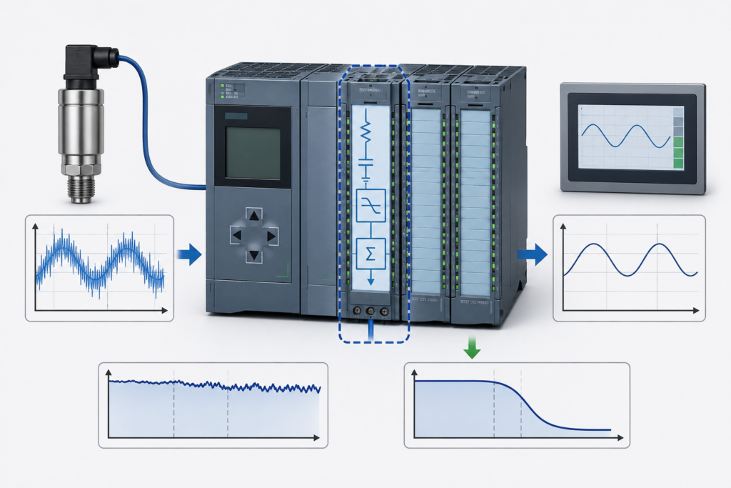
Analog filtering is widely used in industrial automation because real-world signals are rarely perfectly clean.
Pressure transmitters fluctuate. Level sensors react to turbulence. Temperature readings move by a few counts. Long field cables pick up electrical noise from motors, contactors and variable-frequency drives.
A filter can make these values easier to use. It removes short spikes, reduces nuisance alarms and creates smoother trends.
But filtering always comes with a cost: delay.
When the filter is too strong, the PLC sees a calm and stable value while the real process has already changed. This creates false confidence and can delay interlocks, shutdowns and control-system reactions.
Filtering should remove unwanted noise—not hide genuine process movement.
What Analog Filtering Does
An analog filter does not normally improve the sensor itself. It changes how quickly the measured value is allowed to move.
A simple filtered signal may be calculated by combining:
- Part of the newest measurement
- Part of the previous filtered result
The filter reduces sudden changes, producing a smoother output.
For example, the raw pressure value might jump between:
- 4.82 bar
- 4.95 bar
- 4.87 bar
- 5.01 bar
After filtering, the PLC might see:
- 4.88 bar
- 4.89 bar
- 4.89 bar
- 4.91 bar
The displayed value looks cleaner, but it also reacts more slowly.
Where Filtering Can Occur
A single analog signal may be filtered in several different places:
- Inside the sensor
- Inside the transmitter
- In the analog input module
- In the PLC program
- Inside a PID controller
- In the HMI trend
- In a historian or SCADA system
This matters because the delays accumulate.
A transmitter may have three seconds of damping. The analog module may add another second. A software averaging block may add several more seconds. The HMI trend may then refresh only once per second.
The operator may be looking at a signal that represents process conditions from several seconds earlier.
During normal operation, that may go unnoticed. During a fast pressure rise, low-level event or shutdown condition, it can become dangerous.
How Excessive Filtering Delays an Interlock
Consider a process where a pump must stop when suction pressure falls below 1.5 bar.
The actual pressure drops quickly:
- Real pressure: 2.2 bar
- One second later: 1.3 bar
Without excessive filtering, the PLC detects the low-pressure condition and stops the pump.
With a heavily filtered value, the controller may still see:
- 2.0 bar
- 1.8 bar
- 1.6 bar
- 1.4 bar
The shutdown occurs only after the filtered value finally crosses the limit.
The pressure switchpoint itself may be correct. The PLC logic may also be correct. The problem is that the signal reaching the interlock is delayed.
This is known as dead time or measurement lag.
A Smooth Trend Does Not Prove a Stable Process
One of the most misleading commissioning observations is a perfectly smooth analog trend.
A clean trend may indicate:
- A stable process
- A well-installed sensor
- Effective noise reduction
But it may also indicate:
- Excessive transmitter damping
- Heavy software averaging
- Slow HMI sampling
- Stale communication data
- A frozen analog module
- A process oscillating faster than the trend can display
For example, a pressure signal may oscillate rapidly between 4 and 6 bar. A slow-moving average can display an apparently stable value near 5 bar.
The HMI looks reassuring while the real process is unstable.
Always compare the filtered value with the raw measurement during commissioning.
Startup Overshoot Caused by Filter Delay
Filtering can also create poor startup behaviour.
Imagine a pump or heater controlled from a filtered temperature value.
At startup:
- The actual temperature begins rising.
- The filtered value changes slowly.
- The controller believes more heating is still required.
- The output remains high.
- The actual temperature passes the target.
- The filtered value catches up later.
- The controller finally reduces its output.
The result is overshoot.
A technician may respond by reducing controller gain, increasing integral time or changing the setpoint. Those changes may hide the symptom but fail to address the real cause: the measurement is arriving too late.
Before tuning a PID loop, confirm how much filtering and damping exist throughout the measurement chain.
Delayed Permissives
Filters are sometimes applied to permissives to prevent nuisance trips.
For example, a machine may be permitted to start only when:
- Pressure is above 3 bar
- Flow is above 20 litres per minute
- Temperature is below 60°C
A delay can be useful when the raw signal contains short harmless fluctuations.
However, the same filter may also delay the removal of the permissive after a genuine process failure.
This creates two different requirements:
- The signal should not trip because of a brief noise spike.
- The system must react quickly when the process truly becomes unsafe.
A slow analog filter is not always the best way to achieve both.
A more controlled solution may use:
- Separate alarm and trip thresholds
- Hysteresis
- On-delay confirmation
- Short off-delay where appropriate
- Rate-of-change monitoring
- A dedicated hardwired switch for critical protection
These methods make the intended timing more visible than a heavily smoothed measurement.
Filtering Versus Alarm Delay
Filtering and alarm delays are not the same.
Analog filtering
Changes the actual measurement used throughout the program.
Every block receiving the filtered value sees the delayed signal.
Alarm delay
Allows the measurement to remain raw or lightly filtered but requires the alarm condition to persist for a defined period.
For example:
- Pressure must remain below 1.5 bar for 500 milliseconds before tripping.
This can reject brief disturbances without hiding the actual pressure from the rest of the program.
For many interlocks, an explicit timer is easier to understand and validate than a long filter constant.
Input-Module Filtering
Analog input modules may offer selectable integration or interference-suppression settings.
These settings can reduce noise caused by mains-frequency interference, often at 50 or 60 Hz. Longer integration times generally produce more stable values but slower updates.
The configured module update time should be checked during commissioning.
A technician may inspect the PLC code and find no software filter, while the analog module itself is already averaging the signal.
Module settings should therefore be reviewed together with:
- Sensor response time
- Transmitter damping
- PLC cycle time
- Network update time
- Software filtering
The PLC program is only one part of the measurement chain.
Moving-Average Filters
A moving-average filter stores several recent samples and calculates their average.
For example, a ten-sample moving average might calculate:
Filtered value = Sum of last 10 samples ÷ 10
This is simple and effective for random noise.
However, increasing the number of samples increases delay.
If the PLC samples every 100 milliseconds:
- 5 samples cover 0.5 seconds
- 20 samples cover 2 seconds
- 100 samples cover 10 seconds
A 100-sample average may look beautifully smooth, but it may be unsuitable for a fast interlock.
The sample interval matters just as much as the number of samples.
Low-Pass or Exponential Filters
A common PLC filter uses a weighting factor:
Filtered = Filtered old + Factor × (Raw − Filtered old)
A small factor creates strong smoothing and a slow response.
A large factor follows the raw signal more closely.
The main advantage is that this type of filter requires little memory and is easy to implement. The disadvantage is that its time response is not always obvious to technicians reading the program.
Filter parameters should therefore be documented in meaningful engineering terms where possible, such as approximate response time, rather than leaving an unexplained coefficient such as 0.03.
Use Different Signals for Control and Protection
One filtered value should not automatically be used for everything.
A useful design may create separate signal paths:
- Raw value for diagnostics and fast protection
- Lightly filtered value for control
- Heavily filtered value for operator display or long-term trending
For example:
- Raw pressure detects a sudden dangerous drop.
- Filtered pressure feeds the PID controller.
- Smoothed pressure appears on the HMI.
This allows each function to use a signal appropriate to its purpose.
The raw value should still be checked for noise and validity. It should not be used blindly where false spikes could cause unnecessary trips.
Rate-of-Change Detection
A heavily filtered value may react too slowly to a rapidly developing fault.
Rate-of-change monitoring can provide an additional warning.
Examples include:
- Pressure falling faster than 0.5 bar per second
- Temperature rising faster than 3°C per minute
- Tank level changing faster than physically expected
- Flow collapsing suddenly despite a still-normal filtered average
Rate monitoring can detect that the process is moving in a dangerous direction before the filtered value reaches the final alarm threshold.
It should be used carefully because noisy signals can produce false rate alarms. A lightly filtered or validated signal is usually more suitable than a completely raw value.
How to Detect Overfiltering
Possible signs include:
- The physical process changes before the PLC value reacts.
- Interlocks clear or activate noticeably late.
- Startup repeatedly overshoots.
- Shutdown response feels sluggish.
- The HMI trend looks smoother than a handheld instrument.
- A valve or pump continues running after the process condition has already changed.
- PID tuning requires unusually weak settings.
- Raw and filtered values differ significantly during transitions.
During testing, force or simulate realistic process changes and record both the raw and filtered signals with a PLC trace.
Do not test only under steady-state conditions. A filter reveals its weaknesses during rapid changes.
Commissioning an Analog Filter
A practical commissioning process is:
- Record the raw signal with no software filtering.
- Determine the size and frequency of the actual noise.
- Confirm that wiring, shielding and grounding are correct.
- Check transmitter damping and module settings.
- Apply the smallest amount of filtering that solves the problem.
- Test realistic startup and shutdown conditions.
- Measure the delay from physical change to PLC reaction.
- Verify alarm and interlock response times.
- Document the final filter parameters.
- Keep raw-value access available for troubleshooting.
Filtering should not be used to compensate for defective installation.
Before adding more smoothing, investigate:
- Poor cable shielding
- Incorrect grounding
- Loose terminals
- Damaged sensors
- VFD interference
- Wrong cable routing
- Unstable power supplies
- Improper transmitter configuration
A wiring problem should be repaired, not averaged away.
Common Symptoms and Causes
Delayed permissive removal
Likely causes include excessive analog filtering, transmitter damping or an intentional delay that is too long.
Slow shutdown response
The signal may pass through several filtering stages before reaching the shutdown logic.
Stable HMI trend but unstable equipment
The HMI may be displaying a slow average while the real signal oscillates rapidly.
Analog interlock activates late
The trip logic may use the same filtered value intended for display or PID control.
Startup overshoot
The controller continues increasing its output because the delayed measurement has not yet shown the process response.
Final Thoughts
Analog filtering is valuable, but it is not free.
Every filter trades some response speed for improved stability. Too little filtering can create noisy control and nuisance alarms. Too much filtering can hide real process changes and delay protective action.
The correct goal is not to make every analog trend perfectly smooth.
The goal is to preserve the process information the control system actually needs.
Use filtering to remove electrical noise and irrelevant fluctuations. Do not use it to conceal unstable equipment, bad wiring or genuine process movement.
A clean signal is useful. A clean signal that arrives too late can be worse than a noisy one.