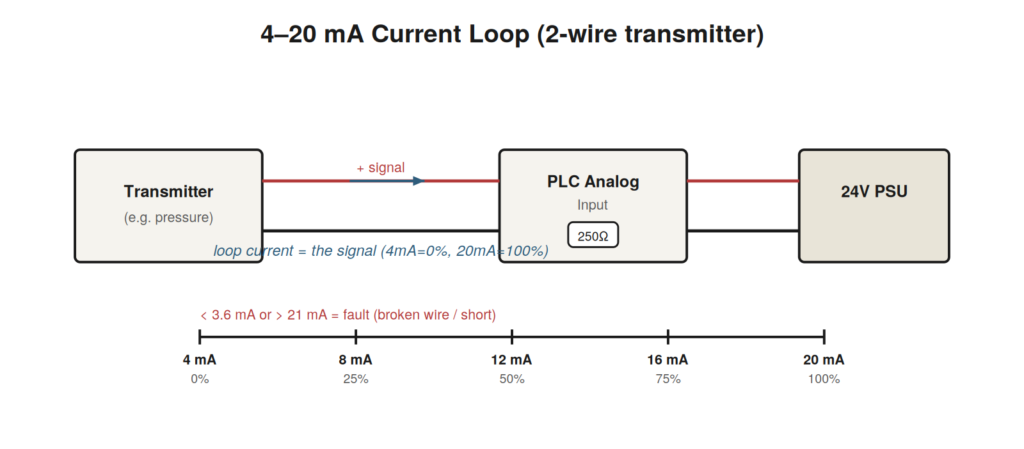
Analog inputs represent a continuous value — a pressure, a
temperature, a level, a flow — as a signal that varies over a range. The
two dominant standards are the 4–20 mA current loop and the 0–10 V
voltage signal, with current loops preferred in industrial settings
because they resist noise and reveal broken wires. Where a digital input
asks ‘is it on?’, an analog input asks ‘how much?’, and troubleshooting
shifts from continuity to accuracy and scaling.
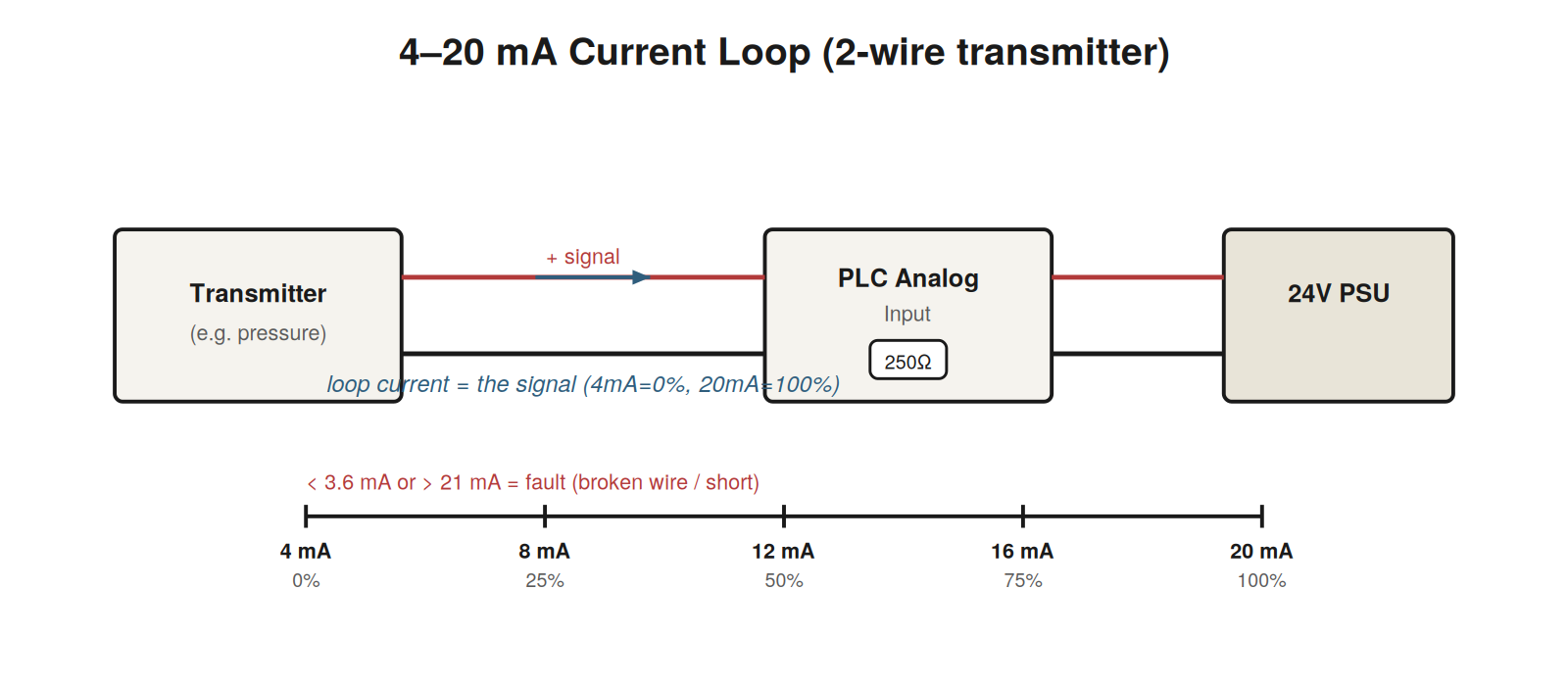
through the entire loop and represents the measured value; 4 mA is 0%
and 20 mA is 100% of range.
Why 4–20 mA is troubleshoot-friendly
The genius of a 4–20 mA loop is that the live zero — 4 mA
representing 0% — lets the system distinguish a genuine zero reading
from a broken circuit. A healthy loop always carries at least 4 mA. If
the wire breaks, the current drops to 0 mA, well below the valid range,
and the input card flags an out-of-range or wire-break fault. A value
pinned at or below about 3.6 mA almost always means an open circuit; a
value pinned high above 20 mA suggests a short or a failed
transmitter.
Scaling: raw counts versus engineering units
The input card converts the current to a raw digital number (counts).
Your program then scales those counts to engineering units — bar, °C,
litres per minute. When an analog reading looks wrong, decide first
whether the problem is the signal or the scaling. Inject a known current
with a loop calibrator: if the raw counts are correct but the
engineering value is wrong, the scaling parameters are the culprit; if
the raw counts themselves are wrong, the problem is upstream in the
field, wiring, or card.
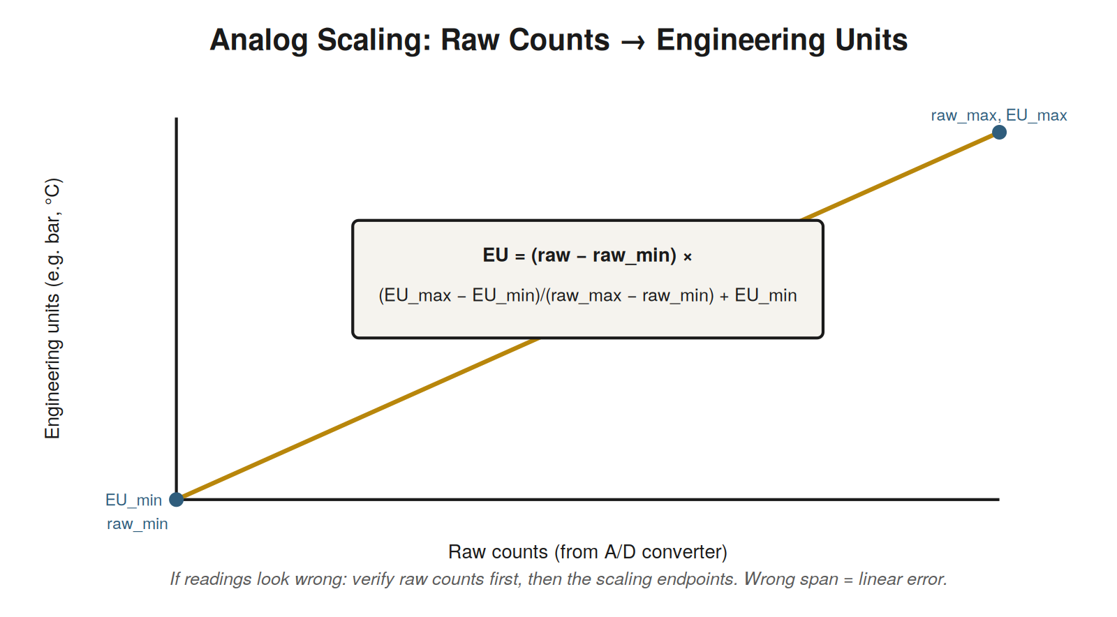
engineering units. A wrong span or offset produces a proportional error,
which is why injecting a known signal isolates scaling problems
immediately.
| Symptom | Likely cause | Test |
|---|---|---|
| Reading stuck at minimum / underrange | Open wire, dead transmitter, no loop power | Measure loop mA; check 24 V supply |
| Reading stuck at maximum / overrange | Short, failed transmitter, miswire | Measure loop mA; inspect for shorts |
| Reading offset by a constant | Scaling offset wrong, sensor calibration | Inject known mA; compare raw vs. EU |
| Reading wrong by a proportion | Scaling span wrong | Inject two points; check endpoints |
| Noisy / jumping reading | EMI, poor shield/ground, loose terminal | Check shielding and grounding; tighten |
Voltage signals and their quirks
While 4–20 mA dominates industrial analog, 0–10 V (and 0–5 V) signals
are common on shorter runs and inside panels. Voltage signals are
simpler to measure — you can read them directly with a meter at the
terminal — but they are more vulnerable to two problems that current
loops resist. First, voltage drop over long wire runs: the further the
signal travels, the more the wire’s resistance eats into it, producing a
reading that falls off with distance. Second, noise: a voltage signal
picks up electrical interference more readily than a current loop, so a
noisy or fluctuating voltage reading often points at cabling routed too
close to power or drives, or a shield that is not properly grounded.
When you meet a voltage analog signal behaving badly, think distance and
noise before you suspect the sensor.
Reading the raw value: your ground truth
The most powerful move in analog troubleshooting is to look at the
raw count — the number the input card produces before your program
scales it. Both platforms let you see this. The raw value is ground
truth about what the card is receiving, stripped of any scaling
assumptions. If the raw count tracks correctly as the process changes
but the displayed engineering value is wrong, the fault is purely in the
scaling math and no amount of checking wiring will help. If the raw
count itself is wrong or frozen, the fault is in the signal chain —
field, wiring, or card — and the scaling is innocent. This single
distinction saves enormous time, because it tells you which half of the
system to investigate.
A worked scaling problem
A tank level reads 20% when you can see it is actually near half
full. Rather than guess, you inject a known signal. Using a loop
calibrator you source 12 mA — exactly mid-range, which should read 50%.
The display shows 20%. So the engineering value is wrong even with a
perfect known input, which points at scaling. You check the scaling
parameters and find the raw-count endpoints were entered for a different
card’s range. Correcting the endpoints, you re-inject 4, 12, and 20 mA
and confirm 0%, 50%, and 100%. The sensor and wiring were fine all
along; the fault was a number in a configuration screen, and injecting a
known signal found it in minutes.
When the reading is noisy
A jumping analog reading that will not settle is usually an
electrical noise problem rather than a sensor problem. The remedies are
physical: ensure the signal cable is shielded and that the shield is
grounded at one end only (grounding both ends can create a current path
that makes noise worse), route the signal cable away from power and
especially from variable frequency drive output cables, and tighten
every connection in the loop since a marginal joint both drops signal
and admits noise. Software filtering can smooth a reading, but reaching
for filtering before fixing the physical cause hides a problem that will
resurface. Fix the wiring, then filter only if the process itself is
genuinely noisy.
A case file: the drifting temperature
A furnace temperature reading has crept steadily higher over several
months relative to a trusted reference thermometer, though the process
itself has not changed. Because the drift is slow and one-directional,
the technician suspects the sensing chain rather than the process. The
sensor is a three-wire RTD, which infers temperature from resistance, so
any resistance added in the sensing path reads as higher temperature.
Inspecting the terminals reveals corrosion at a field junction — added
resistance, growing slowly as the corrosion advanced, producing exactly
a slow upward drift. Cleaning and re-terminating the connection returns
the reading to agreement with the reference. The pattern is worth
remembering: a temperature reading that drifts slowly higher over time,
with no real process change, points at growing resistance in an RTD’s
leads — usually a corroding or loosening connection — long before it
points at a failing sensor element.
Underrange, overrange, and what they mean
Analog input cards flag readings that fall outside the valid range,
and learning to read these flags speeds diagnosis. An underrange
indication — a 4–20 mA loop reading below about 3.6 mA, or a voltage
input below its minimum — almost always means an open circuit somewhere
in the loop: a broken wire, a disconnected sensor, or lost loop power.
The current has dropped below the live zero, which is precisely the
fault-detection behavior the live zero exists to provide. An overrange
indication — current above roughly 21 mA or voltage above maximum —
points instead at a short, a miswire, or a failed transmitter driving
the signal too high. So the direction of the out-of-range condition is
itself diagnostic: underrange sends you looking for an open, overrange
for a short or a failed transmitter. The card is not just failing to
read; it is telling you which kind of fault it sees.
Calibration versus faults: telling them apart
Not every wrong analog reading is a fault; some are calibration
drift, and distinguishing the two directs you to the right remedy. A
genuine fault — a broken wire, a failed transmitter, a wrong scaling
parameter — typically produces a reading that is dramatically wrong,
stuck, or out of range. Calibration drift produces a reading that is
subtly wrong, off by a modest amount that may grow slowly, while still
tracking the process correctly in shape. A pressure reading that shows
the right pattern of rises and falls but sits consistently a bit high is
more likely drifted calibration than a hard fault. The remedy differs: a
fault is repaired by fixing the broken element, while drift is corrected
by recalibrating the sensor or adjusting its scaling to match a trusted
reference. Injecting a known signal helps here too — if a precisely
known input produces a reading off by a small consistent amount,
calibration is indicated, whereas a wildly wrong or unstable response to
a known input points at a fault. Reading the character of the error —
dramatic and stuck versus subtle and tracking — tells you whether to
hunt a fault or to recalibrate.
Multi-channel analog cards and shared references
Analog input cards often carry several channels that may share
references, supplies, or a common ground, and this sharing creates fault
patterns worth recognizing. When several analog channels on one card all
read wrong together, the shared element is the likely cause rather than
a simultaneous failure of several independent sensors — a shared supply
that has sagged, a shared reference that has drifted, a common ground
that has been compromised. This mirrors the shared-common logic of
digital inputs: simultaneity across channels points at what they share.
Conversely, a single channel wrong while its neighbors on the same card
read correctly points at that channel’s own signal path — its field
device, wiring, or the individual channel — since the shared elements
are evidently fine given the healthy neighbors. Reading whether an
analog fault affects one channel or many, and if many whether they share
a card or a supply or a ground, narrows the search the same way it does
for digital inputs, and it prevents the error of recalibrating or
replacing several sensors when one shared reference is the actual
fault.
A structured summary of analog input faults
The analog input material likewise organizes into clear categories
anchored by one decisive test — reading the raw count to see whether the
fault is in the signal or the scaling. Signal-side faults, where the raw
count itself is wrong, subdivide into opens (underrange, from a broken
wire, dead transmitter, or lost loop power), shorts and failures
(overrange, from a short or a failed transmitter driving the signal
high), and noise (an unstable raw value from interference, poor
shielding, or grounding). Scaling-side faults, where the raw count is
correct but the engineering value is wrong, come from incorrect scaling
parameters — wrong endpoints, wrong range, wrong offset — and produce
errors that are proportional and consistent rather than stuck or out of
range. Alongside these sit calibration drift, a subtle consistent error
from a sensor slowly moving out of calibration while still tracking the
process, and shared-element faults, where several channels read wrong
together because they share a supply, reference, or ground. The master
move that sorts signal from scaling is injecting a known signal and
reading the raw count: correct raw with wrong engineering value means
scaling, wrong raw means signal, and this single test directs every
analog input investigation toward the right half of the system before
any component is touched.
A case file: the noisy reading that came and
went
A flow reading is mostly stable but periodically becomes noisy and
jumps around, always during production, never when the line is idle for
maintenance. The correlation with production activity rather than idle
time is the decisive pattern, and it points away from the sensor and
toward electrical noise generated by other equipment running during
production. The flow signal is an analog input, vulnerable to
interference, and something that runs during production is injecting
noise into it. Investigating what differs between production and idle,
the technician finds a large variable frequency drive nearby that runs
only during production, and the flow signal cable is routed close to
that drive’s output cabling — a classic source of electrical
interference. During production the drive runs and couples noise into
the nearby signal cable; during idle maintenance the drive is off and
the signal is clean. Rerouting the signal cable away from the drive
cabling, and confirming the signal cable’s shield is properly grounded
at one end, eliminates the noise. The case captures a frequent analog
fault pattern: a reading that becomes noisy specifically when other
equipment runs is picking up interference from that equipment, and the
fix lies in the physical routing and shielding of the signal cable
rather than in the sensor or the input card, both of which are innocent.
The timing correlation between the noise and the operation of nearby
equipment is what exposes the interference as the cause.