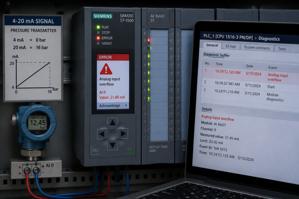
Analog signals do not always remain inside their expected operating range.
A pressure transmitter configured for 0–10 bar may experience 12 bar. A level sensor may exceed its calibrated distance. A 4–20 mA wire may break. A remote analog value may stop updating while its last believable measurement remains stored in the PLC.
Without clear invalid-data handling, the control system may continue operating as though the measurement were healthy.
This can create:
- Incorrect alarms
- Delayed shutdowns
- False startup permissives
- Unstable PID control
- Misleading HMI values
- Overflowed calculations
- Unsafe fallback behaviour
Professional analog logic must define what happens when the measurement is no longer trustworthy.
The Difference Between Overflow and Saturation
Overflow and saturation are related, but they are not identical.
Sensor or transmitter saturation
Saturation occurs when the process moves beyond the measuring capability or configured range of the instrument.
For example:
Configured transmitter range: 0–100%
Actual process condition: 118%
Reported value: approximately 100%
The transmitter cannot accurately represent the additional 18%. Its output remains at or near its upper limit.
The HMI may therefore display a perfectly stable 100% while the real process continues increasing.
PLC calculation overflow
Calculation overflow occurs when a numerical operation exceeds the range supported by its PLC data type.
For example, multiplying two large 16-bit integers during scaling may produce an intermediate result that cannot be stored.
The result may:
- Wrap around
- Become negative
- Jump unexpectedly
- Trigger a calculation error
- Produce an invalid engineering value
A saturated sensor produces a limited measurement. A calculation overflow produces a corrupted number.
Both must be detected and handled.
A Saturated Value Can Look Healthy
A signal fixed at its configured maximum can easily be mistaken for a stable process.
Consider a level transmitter configured as:
- 4 mA = 0%
- 20 mA = 100%
If the tank level rises beyond the transmitter’s measurable range, the signal may remain near 20 mA.
The PLC sees:
Tank_Level = 100%The real tank may be:
Tank_Level_Actual > 100% of calibrated rangeThe trend becomes flat, but that flat line does not prove that the process stopped changing.
Possible saturation indicators include:
- Value remains exactly at the configured maximum
- Value remains exactly at the configured minimum
- Controller output continues increasing without process response
- Related instruments continue changing
- Module overrange diagnostics become active
- Transmitter diagnostic status reports saturation
- Process behaviour contradicts the displayed value
The system should distinguish a genuine maximum process value from an invalid overrange condition.
Clamping Can Hide the Fault
Clamping limits a calculated value to an expected range.
For example:
IF Level_PV > 100.0 THEN
    Level_PV := 100.0;
END_IF;

IF Level_PV < 0.0 THEN
    Level_PV := 0.0;
END_IF;
This can protect downstream calculations and prevent unattractive HMI values such as 104.7%.
However, clamping can also hide:
- Instrument overrange
- Underflow
- Broken wiring
- Incorrect scaling
- Calculation errors
- Invalid diagnostic codes
The operator sees a normal-looking boundary value instead of an instrument fault.
A better structure keeps the displayed or controlled value separate from its quality:
Level_Unclamped
Level_Clamped
Level_Overrange
Level_Underrange
Level_Valid
The PLC may use a clamped value for selected calculations while still generating a clear alarm that the measurement is outside its valid range.
Clamping should limit a value—not erase the reason it was limited.
Broken 4–20 mA Signal
A broken current loop often drives the measured current below the normal 4 mA operating range.
Possible causes include:
- Broken conductor
- Loose terminal
- Disconnected transmitter
- Missing 24 V supply
- Incorrect polarity
- Blown loop fuse
- Failed transmitter electronics
- Damaged junction box
Depending on the module configuration, the PLC may receive:
- A wire-break diagnostic
- Underflow status
- A low raw count
- A channel fault
- An invalid-quality indication
The program should not simply scale that raw count into an engineering value.
For example, a broken pressure signal might otherwise appear as:
Pressure = −2.5 barThat number may trigger a low-pressure alarm, but it does not explain the real problem.
A better diagnostic structure separates:
Pressure_Low_Process
Pressure_Signal_Broken
Pressure_Channel_Fault
A process alarm and an instrumentation fault require different maintenance responses.
Underflow Is Not Always a Broken Wire
A current below the normal measurement range may indicate:
- Process below configured range
- Transmitter fault-current output
- Broken loop
- Incorrect module configuration
- Poor loop power
- Calibration error
The meaning depends on the transmitter and analog input configuration.
Similarly, a current above the normal range may indicate:
- Genuine process overrange
- Transmitter alarm current
- Incorrect wiring
- Module fault
- Scaling error
Do not assume that every value below 4 mA or above 20 mA has the same meaning.
Review the transmitter fault-current configuration and the analog module diagnostic thresholds.
Invalid Network Data
Many analog measurements now reach the PLC through:
- PROFINET
- EtherNet/IP
- Modbus TCP
- Modbus RTU
- PROFIBUS
- Another PLC
- A remote telemetry system
- An intelligent drive or instrument
When communication fails, the numerical tag may not automatically become zero.
Depending on the system design, it may:
- Retain its last value
- Move to a substitute value
- Become zero
- Contain a diagnostic code
- Stop updating without changing
- Be marked invalid by a separate status bit
A frozen value can be particularly dangerous because it remains believable.
For example:
Remote_Pressure = 5.2 barmay stay unchanged for ten minutes after communication fails.
The HMI shows a stable process, while the PLC is using old information.
Detecting Frozen Values
A value should not be considered valid merely because it remains within its expected range.
Useful validity checks include:
- Communication connection status
- Device diagnostic state
- Heartbeat bit
- Incrementing update counter
- Timestamp
- Signal age
- Data-quality code
- Sequence number
A networked measurement might be validated as:
Remote_Pressure_Valid :=
    Remote_Communication_Healthy
    AND Remote_Device_Healthy
    AND Remote_Data_Quality_Good
    AND Remote_Signal_Age < Maximum_Age;
The process value and its quality should always travel together.
Do Not Use “Value Changed” Alone as a Watchdog
A common attempt to detect frozen data is checking whether the measurement changes.
This can create false alarms because a genuinely stable process may remain at the same value for a long time.
For example, tank temperature may correctly stay at 20.0°C for several minutes.
A better method is to monitor:
- Communication heartbeat
- Update counter
- New-data flag
- Timestamp
These prove that fresh information is arriving even when the process value itself remains constant.
Failed Analog Module Behaviour
An analog module fault may produce different results depending on the PLC platform and fault type.
Possible behaviour includes:
- Channel value moves to a substitute value
- Last value remains available
- Diagnostic code appears
- Module becomes unavailable
- Input update stops
- CPU generates an I/O fault
- Program receives an out-of-range raw count
The PLC program should use module diagnostics rather than relying only on the process value.
Useful status information includes:
Module_Healthy
Channel_Healthy
Wire_Break
Underflow
Overflow
Configuration_Fault
Value_Valid
A stable number from an unhealthy channel is still invalid.
Scaling Overflow
Scaling calculations can overflow when intermediate results exceed the variable’s numeric range.
Consider:
Scaled_Value :=
    Raw_Value
    × Engineering_Span
    ÷ Raw_Span;
Suppose Raw_Value and Engineering_Span are both large integers. Their product may exceed the capacity of a 16-bit variable before division reduces it.
The final expected answer may be reasonable, but the intermediate calculation is not.
Possible protections include:
- Converting to floating-point before multiplication
- Using larger integer types
- Normalizing before applying the engineering span
- Checking calculation status
- Validating inputs before scaling
- Testing minimum and maximum values
For example:
Normalized :=
    REAL(Raw_Value - Raw_Minimum)
    /
    REAL(Raw_Maximum - Raw_Minimum);

Engineering_Value :=
    Engineering_Minimum
    +
    Normalized
    ×
    (Engineering_Maximum - Engineering_Minimum);
The exact implementation depends on the PLC platform, but the data types must support the complete calculation.
Division by Zero and Invalid Configuration
A scaling block may fail if:
Raw_Maximum = Raw_MinimumThis creates division by zero.
The condition may occur because of:
- Uninitialized parameters
- Incorrect recipe loading
- Corrupted configuration
- Failed data transfer
- Programmer error
- HMI entry mistake
A reusable scaling function should detect invalid configuration before performing the calculation:
Scaling_Config_Valid :=
    Raw_Maximum > Raw_Minimum
    AND Engineering_Maximum <> Engineering_Minimum;
When configuration is invalid, the block should:
- Mark the output invalid
- Generate a diagnostic alarm
- Apply the defined fallback
- Avoid continuing with the calculation
Signed, Unsigned and Conversion Errors
Incorrect data interpretation can create apparently random process values.
Common problems include:
- Negative values stored in unsigned variables
- Signed raw counts interpreted as large positive numbers
- Floating-point values converted to integers too early
- Incorrect byte order
- Word swapping in Modbus communication
- Fixed-point values interpreted without their decimal factor
For example, a signed value representing −1 may appear as 65,535 when interpreted as an unsigned 16-bit number.
That false value can then overflow scaling calculations or activate high alarms.
Every analog data interface should document:
- Data type
- Signed or unsigned format
- Byte order
- Word order
- Decimal multiplier
- Engineering unit
- Valid range
PID Behaviour During Saturation
A saturated process value can destabilize a control loop.
Suppose a temperature transmitter is limited to 200°C. The actual process reaches 230°C, but the PLC continues receiving approximately 200°C.
The PID controller cannot see the additional temperature rise.
Depending on the control direction and setpoint, it may continue making inappropriate output decisions.
Saturation may also interact with integral action. The controller output can remain at its limit while the integral term continues accumulating, causing slow recovery after the measurement returns to range.
A robust design should consider:
- Measurement overrange
- Controller output saturation
- Integral windup protection
- Invalid process-value handling
- Safe manual fallback
- Alarm and shutdown requirements
Retuning the PID does not repair a saturated instrument.
False Permissives
Analog measurements often create digital startup conditions:
Pressure_Healthy := Pressure_PV > 3.0;If Pressure_PV is frozen at 4.5 bar after communication loss, the startup permissive remains true.
The machine may start without real pressure confirmation.
A safer permissive includes validity:
Pressure_Permissive :=
    Pressure_Valid
    AND Pressure_PV > 3.0;
Where required, it may also include stability:
Pressure_Permissive :=
    Pressure_Valid
    AND Pressure_Above_Limit
    AND Pressure_Stable;
The process condition and signal quality are separate requirements.
Invalid Data Must Have a Defined Response
When an analog measurement becomes invalid, the program needs a clear strategy.
Possible responses include:
- Immediate equipment trip
- Controlled shutdown
- Block new startups
- Hold the current output temporarily
- Switch to manual control
- Use a redundant sensor
- Apply an approved substitute value
- Enter a degraded operating mode
- Continue for a limited time with an alarm
The correct behaviour depends on:
- Process risk
- Measurement purpose
- Equipment response time
- Availability of redundant information
- Consequences of stopping
- Consequences of continuing
The fallback must be deliberate.
Leaving the last valid value active indefinitely is not a fallback strategy. It is an undefined assumption.
Fail-High and Fail-Low Assumptions
Some systems replace an invalid value with a high or low substitute.
For example:
IF NOT Pressure_Valid THEN
    Pressure_For_Protection := 0.0;
END_IF;
This may force a low-pressure shutdown.
In another application, an invalid level signal might be replaced with 100% to prevent tank filling.
These fail-high or fail-low choices can be useful, but only when based on the process risk assessment.
A single universal substitute is not appropriate for every function.
The same invalid measurement may need different handling for:
- Shutdown logic
- PID control
- HMI display
- Historical logging
- Startup permissives
Redundant Measurements
Critical processes may use two or more sensors.
Redundancy can help detect:
- Sensor drift
- Saturation
- Frozen values
- Scaling mismatch
- Wiring faults
For example:
Pressure_Disagreement :=
    ABS(Pressure_A - Pressure_B)
    > Maximum_Allowed_Difference;
However, redundancy introduces additional design decisions:
- Which sensor controls the process?
- What happens when they disagree?
- Can one sensor be selected manually?
- Is voting required?
- How is maintenance performed?
- How is a common-mode failure detected?
Two sensors with the same incorrect range or shared power supply can fail together. Redundancy must consider the complete measurement architecture.
Preserve the Last Value Without Calling It Valid
Retaining the last good value can be useful for diagnostics and HMI history.
For example:
Pressure_Last_Good_Value
Pressure_Last_Good_Time
When the signal becomes invalid, the HMI may display:
Last valid pressure: 5.2 bar at 14:32:16
Current signal status: invalid
This is much clearer than continuing to display 5.2 bar as though it were live.
Value retention and value validity are different concepts.
HMI Representation of Invalid Data
The HMI should not represent every signal problem as a normal number.
Useful indications include:
BAD SIGNALWIRE BREAKOVERRANGEUNDER-RANGESTALE DATACOMMUNICATION LOSTMODULE FAULTSCALING ERROR
The display may show the last known value, but its invalid status should be obvious.
Avoid replacing all invalid measurements with zero. A zero may be interpreted as a real process condition and can obscure the difference between an empty tank and a failed level transmitter.
Alarm Priorities
Instrumentation faults and process alarms should be separated.
For example:
High_Pressure_Process_Alarm
Pressure_Transmitter_Overrange
Pressure_Signal_Invalid
Pressure_Module_Fault
Pressure_Communication_Lost
These alarms have different meanings.
A high-pressure process alarm indicates that a valid measurement exceeded a limit.
An overrange alarm indicates that the measurement may no longer accurately represent the process.
A communication alarm indicates that no current measurement is available.
Combining all of them into Pressure_Fault slows troubleshooting and can hide the real risk.
Invalid Data During Startup
Power recovery is a vulnerable period for analog measurements.
A typical sequence may be:
- PLC enters RUN.
- Analog module initializes.
- Raw tag contains zero or a substitute value.
- Scaling logic executes.
- Low-process alarm becomes active.
- Transmitter data becomes valid later.
- Filter slowly recovers.
- Reset remains blocked.
Another possibility is that the last retained value appears healthy before fresh data arrives, allowing a false startup permissive.
A deterministic startup should wait for:
- Module healthy
- Channel configured
- Signal valid
- Fresh measurement received
- Filter initialized
- Process condition stable
Only then should the analog value be used for startup decisions.
A Practical Analog Data Structure
A professional analog function block may provide:
Raw_Value
Engineering_Value
Filtered_Value
Control_Value
Display_Value

Signal_Valid
Wire_Break
Underflow
Overflow
Overrange
Communication_Healthy
Data_Stale
Module_Fault
Scaling_Fault

Last_Good_Value
Last_Good_Time
Fallback_Active
This structure separates the number from the confidence the PLC has in that number.
Recommended Troubleshooting Workflow
When a value appears saturated, frozen or invalid:
- Verify the actual physical process independently.
- Measure the transmitter output.
- Check whether the transmitter has reached its configured range.
- Review transmitter diagnostic and fault-current settings.
- Inspect loop wiring and supply voltage.
- Check analog module channel diagnostics.
- Monitor the raw input count.
- Verify scaling limits and data types.
- Check for clamping logic.
- Confirm whether the value is still updating.
- Review communication heartbeat and signal age.
- Compare raw, scaled and filtered values.
- Test under-range, overrange and open-loop conditions.
- Confirm the programmed fallback response.
- Verify how the HMI displays each invalid state.
Do not adjust alarms or PID settings until the signal validity problem has been identified.
Commissioning Tests
Every important analog channel should be tested for:
- Normal minimum input
- Mid-range input
- Normal maximum input
- Under-range current
- Overrange current
- Open circuit
- Short circuit where applicable
- Loss of transmitter power
- Analog module removal or fault
- Network communication loss
- Frozen update counter
- Scaling configuration error
- PLC restart
- Transmitter recovery
- Filter initialization
- Fallback activation and removal
Confirm that:
- Invalid data is recognized
- Startups are blocked when required
- Outputs move to the defined state
- The HMI displays the correct fault
- The last value is not mistaken for live data
- Recovery requires the proper validation
Safety-Related Measurements
Where an analog measurement performs a safety-related function, ordinary PLC diagnostics may not be sufficient.
The required design may involve:
- Safety-rated sensors
- Fail-safe analog modules
- Redundant measurement channels
- Safety PLC logic
- Independent hardwired protection
- Validated fault response
The correct architecture must follow the machine or process risk assessment and applicable safety requirements.
A standard analog tag with a Valid bit should not be treated as a replacement for a properly designed safety function.
Final Thoughts
Analog failures are not limited to noisy signals.
A value can become saturated, overflow a calculation, freeze after a network failure or remain stable while the input module is unhealthy.
The most dangerous measurement is often not an obviously impossible number.
It is a believable value that is no longer valid.
Professional PLC logic should always define:
- How invalid data is detected
- Which diagnostic states are monitored
- What happens during underflow or overflow
- How stale network values are rejected
- Which fallback condition is used
- How alarms are presented
- How the signal is validated after recovery
Never allow a process to continue indefinitely because the last number looked reasonable.
The PLC must know not only the process value, but whether that value can still be trusted.