PLC communication faults have a special talent.
They can make a perfectly good machine look completely broken.
One minute the line is running. Next minute the HMI screams “communication error,” a remote I/O station goes red, a VFD disappears from the network, and the operator says the machine “lost its brain.”
Usually, the PLC did not lose its brain.
Usually, something much more boring happened.
A cable is loose. A switch lost power. Someone changed an IP address. A Profinet device name is wrong. A Modbus slave is not responding. A network plug is half-clicked in but not fully seated, which is honestly one of the most annoying faults on earth.
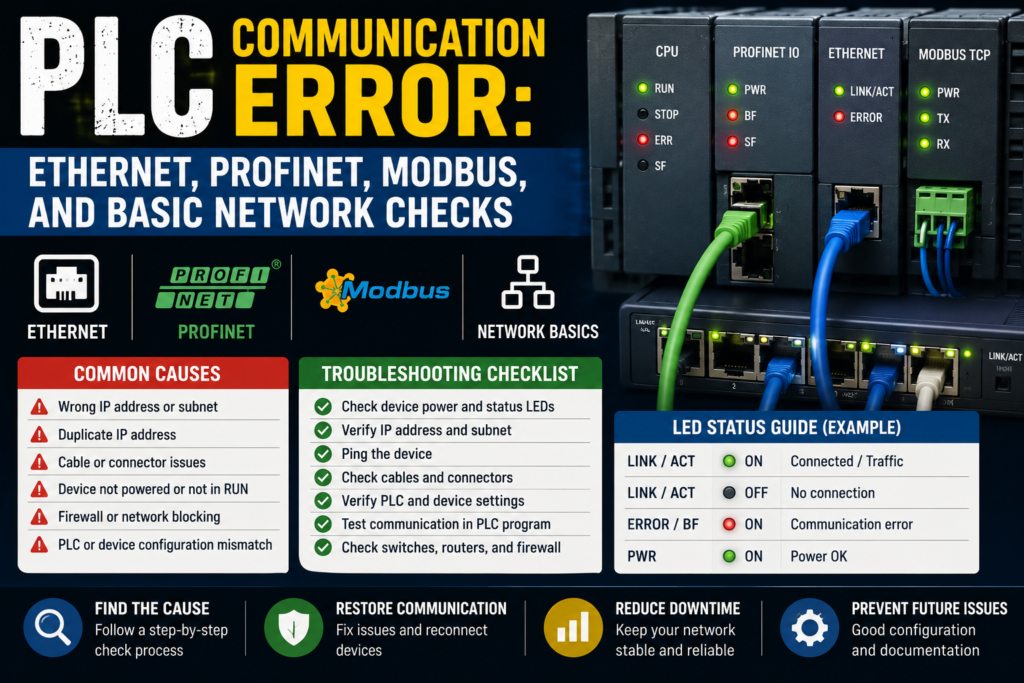
This post is a practical checklist for troubleshooting PLC communication errors, especially on industrial Ethernet, Profinet, Modbus TCP, and basic Modbus RTU networks.
Not deep network engineering. Not theory for a university exam. Just the stuff you check first when the machine is stopped and everybody is staring at you like you personally invented the fault.
First: What Kind of Communication Error Is It?
Before testing anything, try to identify what actually went offline.
Not all communication errors are the same.
Ask:
- Is the PLC offline?
- Is the HMI not talking to the PLC?
- Is one remote I/O station missing?
- Are all remote I/O stations missing?
- Is only one drive offline?
- Is Modbus data not updating?
- Is the entire Ethernet network dead?
- Did the fault start after maintenance, replacement, or software changes?
That last question matters a lot.
If the problem started after someone replaced a VFD, changed an HMI, connected a laptop, updated a PLC program, or swapped an Ethernet cable, don’t ignore the timing. Machines rarely believe in coincidence.
Communication faults usually fall into one of these groups:
- Physical connection problem
- Power problem
- Wrong IP address
- Wrong device name
- Wrong communication settings
- Failed switch or network hardware
- Damaged cable
- Duplicate IP address
- PLC configuration mismatch
- Modbus address or register problem
- Device fault
- Noise or grounding issue
Sounds like a lot, yes.
But you don’t check it randomly. You follow the chain.
1. Check the HMI or PLC Diagnostic Message
Start with the easiest clue.
Look at the HMI alarm screen or PLC diagnostics.
Common messages may look like:
- “PLC communication error”
- “Remote I/O station fault”
- “Profinet device not reachable”
- “Modbus timeout”
- “Drive communication lost”
- “Connection failed”
- “Device name mismatch”
- “I/O access error”
- “Bus fault”
- “Ethernet link down”
Do not just read the alarm title. Open the alarm detail if the HMI has one.
A good diagnostic screen may show:
- Device name
- IP address
- Station number
- Faulted module
- Port number
- Network name
- Error code
- Last active time
- Connection status
That information saves time.
For example, “communication error” is vague. But “Profinet device ET200SP_3 not reachable” is useful. Now you know exactly which remote I/O station to inspect.
Some machines have poor alarms, though. Just a red banner saying “communication fault.” Thanks, very helpful. In that case, go to the PLC software or network device diagnostics if possible.
2. Check Power to the Network Devices
This is the boring check that people skip.
Do the devices actually have power?
Check:
- Remote I/O power
- Ethernet switch power
- HMI power
- VFD control power
- Servo drive control power
- PLC power
- 24V DC power supply
- Control circuit breakers
- Fuses
- Power connectors
A remote I/O station cannot communicate if its 24V supply is gone. A managed switch cannot pass data if its power supply has tripped. A drive may have main power but no control power. Sneaky little detail.
Look for power LEDs.
Good signs:
- Power LED on
- Device status normal
- Switch LEDs active
- PLC in RUN mode
- Remote I/O module powered
Bad signs:
- No power LED
- 24V missing
- Control breaker tripped
- Power supply cycling
- Burnt smell
- Device restarting repeatedly
- Switch completely dark
Measure the 24V DC supply with a multimeter. Don’t only trust the LED.
A weak 24V supply can cause devices to restart randomly, which then creates intermittent communication faults. Those are the fun ones. And by fun, I mean miserable.
3. Check Ethernet Cables and Connectors
For Ethernet-based PLC communication, cables are the first physical thing to inspect.
Check:
- RJ45 plugs fully inserted
- M12 Ethernet connectors tight
- Cable damage
- Crushed cable sections
- Broken locking tabs
- Oil or water inside connectors
- Cable pulled too tight
- Wrong cable route near moving parts
- Cable shield condition
- Patch cable quality
A plug can look connected but not actually click properly. Always push it gently and confirm it is seated.
If the machine has M12 industrial Ethernet connectors, check that they are tightened properly. Loose M12 connectors can cause intermittent link drops, especially with vibration.
Good signs:
- Link LED on at both ends
- Activity LED blinking
- Cable physically secure
- No visible damage
- Connector dry and clean
Bad signs:
- No link LED
- Link LED flickering randomly
- Damaged cable jacket
- Broken RJ45 clip
- Loose M12 connector
- Oil-filled connector
- Cable crushed in cabinet door
- Cable routed through moving machine parts
If you suspect the cable, replace it temporarily with a known-good cable if safe and practical.
A cable swap is not elegant. But it works.
Just make sure you are testing the correct cable. Industrial cabinets love having 20 blue cables that all look exactly the same.
4. Check Ethernet Switches
Many PLC networks use industrial Ethernet switches.
If one switch fails or loses power, several devices may disappear at once.
Check:
- Switch power LED
- Port link LEDs
- Port activity LEDs
- 24V supply to switch
- Fiber ports, if used
- Ring network status
- Managed switch alarm contact
- Loose terminal power connector
- Network topology
If all devices after one switch are offline, suspect the switch or the uplink cable.
Good signs:
- Switch powered
- Uplink port active
- Device ports active
- No alarm LED
- Ring status healthy, if used
Bad signs:
- Switch dark
- Uplink port off
- Several ports dead
- Alarm LED active
- One port constantly flapping
- Switch very hot
- Moisture or corrosion
- Power connector loose
For managed switches, the web interface or diagnostic tool may show port errors, dropped packets, ring faults, duplicate IP warnings, or link speed problems.
For unmanaged switches, you mostly have LEDs and physical checks. Not fancy, but still useful.
A dead switch can make it look like the PLC, HMI, and drives all failed at once. They didn’t. The road between them disappeared.
5. Check IP Addresses
For Ethernet communication, wrong IP addresses are a classic problem.
Check:
- PLC IP address
- HMI IP address
- Remote I/O IP address
- VFD or servo IP address
- Subnet mask
- Gateway, if required
- Duplicate IP addresses
- Laptop IP settings
- Device replacement settings
Example:
PLC IP: 192.168.0.10
HMI IP: 192.168.0.20
Drive IP: 192.168.0.30
Subnet mask: 255.255.255.0
Those devices are in the same subnet, so they can communicate directly.
But if someone sets the drive to 192.168.1.30 with the same subnet mask, the PLC may not reach it anymore.
Good signs:
- Devices are in the correct subnet
- No duplicate IP addresses
- PLC configuration matches real device IP
- HMI points to correct PLC IP
- Laptop can ping devices, if ping is allowed
Bad signs:
- Wrong subnet
- Duplicate IP address
- Device IP changed after replacement
- HMI points to old PLC address
- Laptop IP not in same range
- DHCP used when fixed IP is expected
- Device returns to default IP after reset
Be careful with duplicate IP addresses. They can create strange, unstable faults. Sometimes communication works, then drops, then comes back, then drops again. Like the network is possessed.
It isn’t possessed.
Two devices are fighting for the same address.
6. Use Ping, But Don’t Worship It
Ping is a useful basic test.
From a laptop, you can check whether a device responds on the network.
Example:
ping 192.168.0.10If the device replies, your laptop can reach it.
Good sign:
Reply from 192.168.0.10Bad sign:
Request timed out
Destination host unreachable
But ping is not the whole story.
A device may reply to ping but still not communicate with the PLC because:
- Wrong Profinet device name
- Wrong Modbus port
- Firewall blocks software connection
- PLC configuration mismatch
- Device not assigned to controller
- Wrong protocol selected
- Device in fault state
- PLC is trying another IP
- Communication service disabled
Also, some devices are configured not to reply to ping.
So use ping as a quick check, not as final proof.
Ping tells you, “I can see something at this IP.”
It does not tell you, “The machine protocol is working perfectly and everyone is happy.”
7. Check Profinet Device Names
With Profinet, IP address matters, but device name is often just as important.
In many Siemens/Profinet systems, the PLC expects a device with a specific Profinet name. If the device name is wrong, the PLC may refuse to communicate even if the IP address looks correct.
Check:
- Configured Profinet device name in PLC project
- Actual assigned device name
- IP address
- Device type
- Module configuration
- Slot configuration
- Firmware compatibility
- Network topology, if used
Common Profinet issue after replacing a device:
The new remote I/O module is physically installed and powered. The cable is connected. The IP might even be correct. But the Profinet name was never assigned.
So the PLC still says device not reachable.
Good signs:
- Actual device name matches PLC project
- Device appears in accessible devices
- No name mismatch
- Module configuration matches hardware
- PLC diagnostics show device OK
Bad signs:
- Device has default name
- Device name missing
- Wrong name assigned
- Duplicate Profinet name
- Wrong module type
- Missing submodule
- Configuration mismatch
For Siemens systems, tools like TIA Portal can scan accessible devices and assign device names. Other brands have their own tools.
A Profinet name mismatch is one of those faults that feels invisible until you know to check it.
Then it’s obvious.
Annoyingly obvious.
8. Check Profinet Remote I/O Modules
Remote I/O stations are common in modern machines.
If a remote I/O station goes offline, the PLC may lose several sensors and outputs at once.
Check:
- Power to interface module
- Network cable
- Link LEDs
- Bus status LEDs
- Module status LEDs
- Fault LEDs on individual modules
- Backplane connection
- End module, if required
- Correct module order
- Correct hardware configuration
- Device name and IP address
If only one input card shows a fault, the network may be fine and the problem may be that specific module.
If the entire remote station is offline, check power, network, device name, and interface module.
Good signs:
- Interface module powered
- Link active
- Station visible in PLC diagnostics
- All modules healthy
- Inputs and outputs updating
Bad signs:
- Bus fault LED
- Station not reachable
- Module mismatch
- Missing module
- Wrong module order
- No link LED
- 24V missing
- Device name wrong
A remote I/O station is like a small village connected to the PLC. If the road is blocked, the PLC loses the whole village. If one house has a problem, only one module complains.
That’s a strange analogy, but it works.
9. Check Modbus TCP Settings
Modbus TCP runs over Ethernet, so basic network checks still apply.
Check first:
- Ethernet cable
- Switch
- IP address
- Subnet mask
- Port 502
- Slave/server IP address
- PLC/client settings
- Unit ID, if required
- Register addresses
- Function codes
- Timeout settings
- Polling rate
In Modbus TCP, one device usually acts as the client/master and requests data. The other device acts as server/slave and responds.
Common Modbus TCP faults:
- Wrong IP address
- Device not listening on port 502
- Wrong Unit ID
- Wrong register address
- Wrong function code
- Wrong data type
- Register offset confusion
- Firewall or routing issue
- Polling too fast
- Device busy or faulted
Register addressing is a classic headache.
One manual may say register 40001. Another software may expect address 0. Another expects 1. So you read the wrong value and think communication is broken.
Sometimes communication is working, but you are asking for the wrong register.
Good signs:
- Device responds to Modbus requests
- No timeout
- Correct values update
- Error counters stay low
- Polling stable
Bad signs:
- Timeout
- Illegal function
- Illegal data address
- Connection refused
- Values frozen
- Wrong values
- Communication works only sometimes
If using Modbus TCP, a Modbus scanner tool can help test the device from a laptop. Just be careful on live machines. Reading data is usually safer than writing data, but still know what you’re doing.
Writing to the wrong register can cause real machine movement or configuration changes.
And nobody wants “I was just testing Modbus” as the incident explanation.
10. Check Modbus RTU Wiring
Modbus RTU is usually serial communication, often RS-485.
This is not Ethernet. So ping will not help.
Check:
- A/B communication wires
- Polarity
- Shielding
- Termination resistors
- Bias resistors, if required
- Slave address
- Baud rate
- Parity
- Stop bits
- Data bits
- Cable length
- Grounding
- Noise sources
- Correct COM port
Modbus RTU settings must match between master and slave.
Example:
- Baud rate: 9600
- Parity: Even
- Stop bits: 1
- Data bits: 8
- Slave address: 3
If one device is set to 19200 baud and the other is set to 9600, they will not understand each other. It’s like one person speaking fast Lithuanian and the other waiting for slow English. Not happening.
Good signs:
- TX/RX LEDs blink
- Slave responds to requests
- Correct values update
- No CRC errors
- Stable communication
Bad signs:
- No RX activity
- No response from slave
- CRC errors
- Wrong slave address
- A/B reversed
- Communication works only when cable is moved
- Noise-related dropouts
- Missing termination on long cable
A/B polarity can be confusing because manufacturers sometimes label RS-485 lines differently. Some use A/B, some use D+/D-, some use plus/minus, and not everyone agrees. Lovely, right?
If everything else is correct and there is no response, try verifying the polarity according to both device manuals.
11. Check Communication Parameters
This sounds obvious, but settings must match.
For Ethernet-based systems, check:
- IP address
- Subnet mask
- Gateway
- Device name
- Port number
- Protocol type
- Controller assignment
- Rack/slot settings, if required
- Connection resource limits
For serial Modbus RTU, check:
- Baud rate
- Parity
- Stop bits
- Data bits
- Slave address
- Function code
- Register address
- Timeout
- Polling interval
For HMI-to-PLC communication, check:
- Correct PLC driver
- Correct PLC IP
- Correct rack/slot or station settings
- Correct protocol
- Correct tag addresses
- Runtime downloaded correctly
- HMI project matches PLC project
One wrong setting is enough.
Not five wrong settings. One.
That’s why communication faults can be irritating. The cable may be good, power may be good, LEDs may blink, and still nothing works because the HMI is trying to talk to the wrong PLC address.
12. Check After Device Replacement
A lot of communication errors happen after replacing hardware.
Maybe someone replaced:
- PLC CPU
- HMI
- VFD
- Servo drive
- Remote I/O interface
- Ethernet switch
- Profinet module
- Modbus device
- Network cable
After replacement, check:
- Correct part number
- Firmware version
- IP address
- Profinet name
- Modbus address
- Parameters downloaded
- Hardware configuration
- Termination settings
- Safety settings
- Communication mode
- Backup restored
A new device is not always ready out of the box.
It may have a factory default IP. It may not have a Profinet name. It may have default Modbus settings. It may need a parameter file. It may need to be assigned to the PLC controller.
Good sign:
- Replacement device has same communication settings as old device
- Project downloaded successfully
- PLC diagnostics are clear
- Device online and updating
Bad sign:
- Device still has factory settings
- Wrong firmware
- Wrong module type
- Missing name
- IP address conflict
- Parameter mismatch
- PLC shows hardware configuration error
Replacing the device is only half the repair. Configuring it is the other half.
Skipping that part is how you get a shiny new device that still does absolutely nothing.
13. Check for Duplicate IP Addresses
Duplicate IPs are nasty.
Two devices with the same IP address can create unstable, confusing communication faults.
Signs of duplicate IP:
- Communication works sometimes, then fails
- Ping replies change behavior
- HMI connects randomly
- PLC loses one device when another is powered
- Network scanner shows conflict
- Device goes offline after another device starts
- Managed switch reports duplicate address
Check especially after:
- New device installation
- Laptop connection
- Device replacement
- Copying settings from another machine
- Using default IP addresses
- Network expansion
A simple example:
PLC expects drive at 192.168.0.30. But someone connects a new HMI also set to 192.168.0.30. Now the network becomes confused.
Good troubleshooting method:
- Disconnect suspicious device
- Ping the address
- Check ARP table if you know how
- Use network scanner
- Check managed switch diagnostics
- Compare MAC addresses
- Power devices one by one
Don’t leave duplicate IPs unresolved. They don’t “sort themselves out.” They return later at the worst possible moment.
Usually Friday afternoon.
14. Check Network Load and Bad Devices
Sometimes communication fails because the network is overloaded or one device is misbehaving.
Possible causes:
- Too much polling
- HMI reading too many tags too fast
- Modbus requests too frequent
- Broadcast storm
- Faulty switch
- Damaged Ethernet cable
- Bad device flooding network
- Incorrect ring configuration
- Loop in Ethernet network
- Poor grounding or shielding
A network loop can be especially bad. If unmanaged switches are connected incorrectly, the network may flood itself with traffic.
Signs:
- Whole network becomes slow
- Multiple devices drop offline
- HMI freezes
- PLC communication unstable
- Switch LEDs blink constantly and aggressively
- Managed switch reports storm or loop
If a fault appears after someone “just added one cable,” be suspicious.
One cable can create a loop. One laptop can create an IP conflict. One unmanaged switch can make a clean network messy.
Industrial networks are not magic spiderwebs. Topology matters.
15. Check Noise, Grounding, and Cable Routing
Intermittent communication faults may come from electrical noise.
This is more common with long cables, poor shielding, VFDs, servo drives, welders, high-current cables, and bad grounding.
Check:
- Ethernet cable routed near motor power cables
- RS-485 cable near VFD output cables
- Shield connection
- Cabinet grounding
- Cable screen termination
- Damaged shield
- Loose PE connections
- Long unshielded cable runs
- Missing termination resistors
- Poor cable separation
Good signs:
- Communication cable separated from power cables
- Shielded industrial cable used
- Proper grounding
- Stable signal
- No errors during motor start/stop
Bad signs:
- Fault appears when motor starts
- Fault appears when VFD ramps
- Fault appears randomly under load
- CRC errors on Modbus RTU
- Ethernet link drops with vibration
- Cable shield cut or floating
- Communication cable tied to power cable for long distance
If communication faults happen only when a big motor starts, don’t only stare at software settings. Look at EMC, shielding, grounding, and cable routing.
The problem might not be “data.”
It might be electrical noise punching your data in the face.
PLC Communication Error Checklist
Use this checklist when a PLC, HMI, drive, or remote I/O device stops communicating.
Basic Checks
- Read the alarm
- Which device is offline?
- Is it HMI, PLC, drive, remote I/O, or Modbus device?
- Is there an error code?
- Check power
- PLC powered
- Switch powered
- Remote I/O powered
- Drive control power present
- 24V DC stable
- Check cables
- Ethernet cable seated
- M12 connector tight
- No damaged cable
- Link LEDs active
- Try known-good cable if needed
- Check switches
- Power LED on
- Uplink active
- Port LEDs active
- No alarm LED
- No ring fault
- Check IP settings
- Correct IP address
- Correct subnet mask
- No duplicate IP
- HMI points to correct PLC
- PLC expects correct device IP
- Check Profinet
- Correct device name
- Correct IP
- Device assigned to controller
- Hardware configuration matches
- No module mismatch
- Check Modbus TCP
- Correct server IP
- Port 502 available
- Correct Unit ID
- Correct register address
- Correct function code
- Timeout settings reasonable
- Check Modbus RTU
- A/B wiring correct
- Baud rate matches
- Parity matches
- Slave address correct
- Termination correct
- Shielding OK
- Check replacement settings
- New device configured
- Parameters downloaded
- Device name assigned
- Firmware compatible
- Backup restored
- Check for intermittent causes
- Vibration
- Loose connector
- Electrical noise
- Grounding issue
- Cable route problem
- Network loop
Good vs Bad Communication Signs
| Check Area | Good Sign | Bad Sign |
|---|---|---|
| Power | Device power LED on, stable 24V | No power LED, voltage missing, device restarts |
| Ethernet cable | Link LED on, connector secure | No link, loose plug, damaged cable |
| Switch | Port LEDs active, no alarm | Switch dark, uplink down, alarm LED |
| IP address | Correct subnet, no duplicates | Wrong IP, duplicate IP, wrong subnet |
| Ping test | Device replies | Timeout or unreachable |
| Profinet | Device name matches, station online | Name missing, device unreachable, module mismatch |
| Modbus TCP | Stable response, values updating | Timeout, illegal address, frozen values |
| Modbus RTU | TX/RX activity, no CRC errors | No response, A/B reversed, wrong baud rate |
| HMI connection | Tags update normally | “PLC no response,” frozen values |
| Remote I/O | Inputs/outputs updating | Bus fault, station offline |
| Drive network | Drive ready and online | Communication fault, no enable, offline |
Example 1: HMI Says “PLC No Communication”
The operator says the HMI is not working.
The HMI is powered, but values are frozen. It shows “PLC communication error.”
What do you check?
First, check if the PLC is powered and running.
PLC RUN light is on. Good.
Then check the Ethernet cable between HMI, switch, and PLC. Link LED on the HMI port is off.
You inspect the RJ45 connector and find the cable is not fully clicked into the switch.
Push it in. Link LED returns. HMI reconnects.
That’s it.
No software. No program changes. No dramatic PLC replacement.
Just a cable that looked connected but wasn’t.
Example 2: Profinet Remote I/O Not Reachable
Machine stops. HMI alarm says:
“Remote I/O station 2 communication fault.”
You go to the remote I/O box. Power LED is on, but the network fault LED is red.
Ethernet link LED is active.
So power and cable may be OK.
Next, you scan the Profinet network. The device appears, but its Profinet name is wrong. Someone replaced the remote I/O interface and did not assign the correct device name.
Assign the correct name from the PLC project. Restart if required. Station comes online.
Fault cleared.
This is very common after replacing Profinet devices.
The device was alive. The PLC just didn’t recognize it as the expected station.
Example 3: Modbus RTU Device Not Responding
A PLC reads data from a temperature controller over Modbus RTU.
The values are not updating.
You check:
- Controller powered: yes
- RS-485 cable connected: yes
- Slave address: set to 5
- PLC configured slave address: 4
There’s the problem.
The PLC is asking device 4, but the real device is address 5. Nobody answers, so the PLC reports timeout.
Set the correct address in the PLC configuration or device parameter.
Communication returns.
Tiny setting. Big headache.
Common Mistakes When Troubleshooting PLC Communication
The first mistake is blaming the PLC immediately.
A communication fault is often outside the PLC: cable, switch, IP address, power supply, device name, or settings.
The second mistake is checking only software and ignoring the physical layer. If there is no link light, don’t spend one hour changing IP settings. The cable or port may be dead.
The third mistake is assuming a replacement device is already configured. New devices usually need IP addresses, names, parameters, or downloaded settings.
The fourth mistake is mixing up Modbus addressing. Register 40001 in one manual may not be entered as 40001 in your PLC software. Sometimes it becomes 0, sometimes 1, sometimes 40001. Yes, annoying.
The fifth mistake is ignoring intermittent faults. If a device drops offline only during vibration or motor start, check connectors, shielding, grounding, and cable routing.
The sixth mistake is connecting a laptop with a random fixed IP address and accidentally creating a duplicate IP conflict.
Yes, the troubleshooting laptop can become the fault. Slightly embarrassing, but it happens.
Tools for PLC Communication Troubleshooting
You don’t always need fancy equipment, but a few tools help a lot.
Useful tools:
- Multimeter
- Known-good Ethernet cable
- Laptop with correct engineering software
- Network scanner
- Ping command
- Managed switch diagnostics
- Modbus TCP scanner
- USB-to-RS485 adapter
- Modbus RTU test software
- Cable tester
- Electrical drawings
- PLC hardware configuration
- Device manuals
For basic faults, a multimeter and your eyes solve more than people expect.
For Profinet, engineering software is very useful because you can check device names, diagnostics, module faults, and accessible devices.
For Modbus, test software can help confirm whether a slave responds before blaming the PLC program.
And for all systems, drawings matter. Network drawings, IP lists, device names, station numbers, and cable labels can save serious time.
Assuming they are updated.
Which, let’s be honest, is not always the case.
Final Thoughts
PLC communication errors can look scary, but most of them are not mysterious.
The PLC is trying to talk to another device. That device must be powered, connected, correctly addressed, correctly configured, and healthy. If one part of that chain breaks, communication fails.
So don’t jump straight into complicated software diagnostics.
Start simple.
Check power. Check cables. Check link lights. Check switch status. Check IP addresses. Check Profinet names. Check Modbus settings. Check device configuration. Then go deeper.
A good troubleshooting path looks like this:
Power → cable → switch → address → protocol settings → device diagnostics → PLC configuration.
One step at a time.
And before changing anything in the program, push the Ethernet plug in properly.
You’d be surprised how often that fixes the “very serious network fault.”