PLC High-Speed Counters
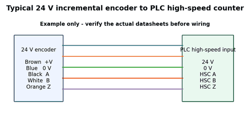
Standard PLC scan-based inputs may be too slow for encoder pulses. High-speed counter hardware captures transitions independently or with dedicated logic. Configuration includes input mode, filter, reset, gate, direction, and rollover behavior.
What to Check
- Identify the exact HSC channel and terminals.
- Confirm quadrature versus pulse/direction mode.
- Check maximum input frequency and filter setting.
Diagnostic Sequence
- Watch raw HSC accumulator while jogging.
- Compare input status bits to physical signals.
- Test direction and reset separately.
Common Mistakes
- Wiring an encoder to normal inputs and counting in ladder logic.
- Enabling a filter that blocks legitimate pulses.
- Resetting the accumulator from multiple program locations.
Field Rule: Prove hardware counting before debugging scaling or sequence logic.
Input Filter Settings
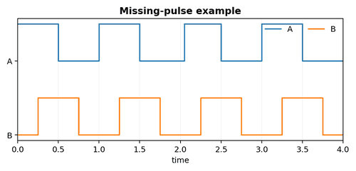
Digital filters reject short pulses to improve noise immunity, but encoder pulses themselves become shorter as speed rises. A filter that is safe at jog speed can remove valid pulses at production speed.
What to Check
- Find minimum pulse width at maximum rpm.
- Find input filter time constant.
- Check whether filter applies to HSC channels.
Diagnostic Sequence
- Reduce filter temporarily within safe limits and compare counts.
- Increase speed gradually while monitoring count error.
- Fix wiring/EMC instead of using excessive filtering.
Common Mistakes
- Using debounce values intended for pushbuttons.
- Setting filters without calculating pulse width.
- Assuming more filtering is always safer.
Field Rule: Filter time must be comfortably shorter than the narrowest legitimate pulse.
Quadrature Counting Modes x1, x2, x4
Controllers may count one edge, both edges of one channel, or all edges of both A and B. The same physical encoder can therefore produce different raw counts per revolution depending on configuration.
What to Check
- Locate the quadrature multiplier setting.
- Mark the shaft and rotate one exact revolution.
- Compare raw count change.
Diagnostic Sequence
- If count is exactly 2× or 4× unexpected, change configuration or scaling deliberately.
- Verify direction after changing modes.
- Document the effective counts per revolution.
Common Mistakes
- Changing both HSC mode and application scale simultaneously.
- Calling x4 “higher encoder resolution” without noting it is decoding.
- Ignoring input frequency impact of the selected mode.
Field Rule: The controller’s effective count resolution is encoder cycles times decoding mode.
PLC Scaling to Engineering Units
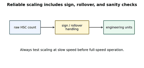
Raw encoder counts need a deterministic scale. Linear axes may use millimetres/count; rotary axes may use degrees/count. Gearboxes, pulleys, circumference, leadscrew pitch, and x4 decoding all influence the conversion.
What to Check
- Write the full mechanical ratio on paper.
- Use exact pulley tooth counts or measured circumference.
- Keep raw count visible for commissioning.
Diagnostic Sequence
- Command a known travel.
- Compare predicted and measured count.
- Calibrate only after mechanical slip is ruled out.
Common Mistakes
- Using trial-and-error scale factors.
- Ignoring gearbox direction.
- Rounding ratios too early.
Field Rule: Derive the scale from mechanics, then verify it with a measured move.
Counter Rollover and Data Types
High-speed counters eventually reach their numeric limit. Signed/unsigned interpretation, rollover, reset strategy, and differences between 16-bit, 32-bit, and 64-bit data can create sudden position jumps that look like encoder faults.
What to Check
- Identify counter width and signedness.
- Calculate time to rollover at maximum rate.
- Inspect code that subtracts successive counts.
Diagnostic Sequence
- Force a controlled near-limit test in simulation or maintenance mode if safe.
- Use rollover-aware delta calculations.
- Trend raw values when reported position jumps by a repeatable large amount.
Common Mistakes
- Resetting frequently without coordinating motion state.
- Casting a large unsigned count into a signed smaller type.
- Assuming a physical encoder cannot cause a negative raw number.
Field Rule: Large repeatable jumps near numeric limits are often software arithmetic, not missing pulses.
Drive Encoder Input Configuration
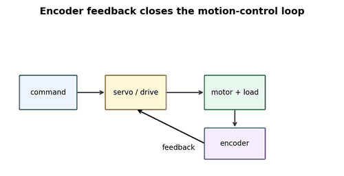
Variable-frequency drives and servo drives may accept multiple feedback types. Parameters can include supply voltage, encoder type, PPR, direction, loss detection, filter, and speed feedback source.
What to Check
- Record parameters before changes.
- Match encoder output interface to the drive option card.
- Confirm PPR and direction.
Diagnostic Sequence
- Use drive diagnostics to view feedback rpm and raw counts.
- Compare motor commanded speed and encoder speed.
- Check feedback loss thresholds and fault history.
Common Mistakes
- Changing parameters without a backup.
- Selecting 5 V encoder supply for a 24 V unit or vice versa.
- Disabling feedback loss detection to keep production running.
Field Rule: The drive is both a receiver and a diagnostic instrument – use its feedback monitors.
Closed-Loop VFD Speed Feedback
A VFD can use encoder feedback to regulate speed more accurately than open-loop operation. Incorrect encoder polarity can make the regulator increase output when speed rises, causing instability or immediate faults.
What to Check
- Verify feedback sign at very low speed.
- Check encoder rpm against motor direction.
- Confirm motor/encoder ratio.
Diagnostic Sequence
- Run uncoupled or in a manufacturer-approved low-risk test when possible.
- Compare open-loop and closed-loop feedback readings.
- Do not enable full closed-loop gains until polarity is proven.
Common Mistakes
- Commissioning feedback at full speed first.
- Reversing motor leads to correct an encoder sign issue without checking machine direction.
- Increasing gains to overcome noisy feedback.
Field Rule: Feedback polarity must be correct before closed-loop tuning.
Servo Feedback Loops
Servo systems use encoder position and speed in fast control loops. Tiny feedback glitches can trigger following error, overspeed, commutation, or encoder alarms. Mechanical stiffness and electrical signal integrity both matter.
What to Check
- Read servo alarm history and subcodes.
- Compare commanded position, actual position, and following error.
- Inspect encoder cable type and shield termination.
Diagnostic Sequence
- Trend error during the exact motion segment that faults.
- Reduce acceleration to separate mechanical slip from signal loss.
- Use manufacturer feedback diagnostics for serial encoders.
Common Mistakes
- Clearing alarms without preserving trace data.
- Changing servo gains before checking mechanical coupling.
- Replacing the motor because the encoder is integrated without checking the cable.
Field Rule: Servo troubleshooting starts with the alarm, motion trace, and feedback path together.
Direction Reversal Problems
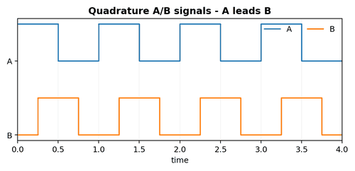
A machine may count correctly forward but lose or jump position during reversal. Causes include coupling backlash, loose hubs, cable flex, quadrature phase problems, and program sign logic.
What to Check
- Compare raw count across reversal.
- Inspect coupling/backlash.
- Scope A/B through zero speed and reversal.
Diagnostic Sequence
- Run small repeated forward/backward moves.
- Check whether error depends on acceleration.
- Separate a fixed backlash error from cumulative lost counts.
Common Mistakes
- Tuning scale to compensate for backlash.
- Blaming one encoder channel without observing both.
- Ignoring cable movement during reversal.
Field Rule: Reversal is a powerful diagnostic because it stresses both mechanics and quadrature direction logic.
Homing with Encoder Feedback
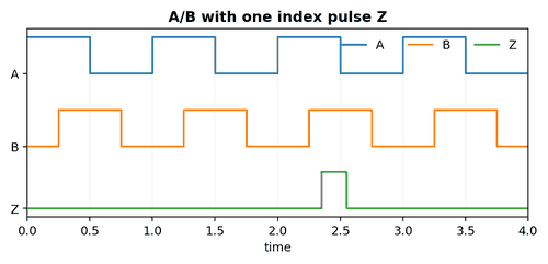
Homing often combines a coarse home sensor with an encoder index. The axis finds the sensor, backs off or creeps, then captures the Z pulse. Inconsistent home position can be caused by sensor hysteresis, missed index, wrong index edge, mechanical slip, or excessive homing speed.
What to Check
- Understand the exact homing sequence.
- Monitor home sensor and Z simultaneously.
- Check capture edge and direction.
Diagnostic Sequence
- Reduce homing speed and compare repeatability.
- Scope Z relative to the sensor transition.
- Check that the index occurs within the controller’s allowed search window.
Common Mistakes
- Changing home offset to hide missed Z events.
- Assuming the sensor alone defines final accuracy.
- Replacing the encoder without checking index alignment.
Field Rule: A repeatable home requires every event in the homing sequence to be repeatable.