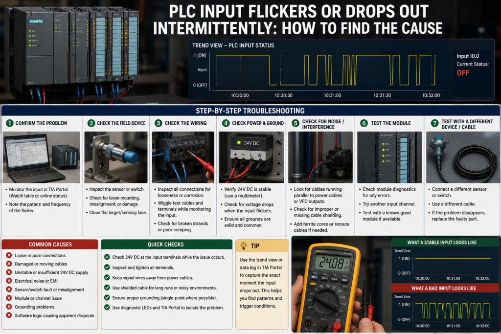
An intermittent PLC input can be one of the most frustrating faults on a machine.
The sensor appears healthy. The input LED is normally on. The machine may run correctly for hours, then suddenly stop because the PLC sees the signal disappear for a fraction of a second.
By the time you connect a multimeter, everything looks normal again.
These faults are rarely solved by staring at the input online and hoping it flickers while you are watching. You need to determine whether the signal is failing at the sensor, along the cable, at the PLC terminal or only inside the program.
Start by Defining the Fault
Before changing anything, identify exactly what is dropping out.
Possible observations include:
- The sensor LED switches off
- The PLC input LED switches off
- The physical input remains on, but the PLC tag changes
- The input tag remains on, but the machine logic resets
- Several inputs fail at the same moment
- The fault appears only when a motor, contactor or solenoid operates
- The signal drops only when a cable or machine section moves
These clues point in different directions.
If the sensor and PLC input LEDs both switch off, begin with the field device, supply and wiring.
If the input LED stays on while the program tag turns off, investigate addressing, software logic, communication and process-image timing.
Step 1: Monitor the Physical Input and Program Signal Separately
Create a watch table containing:
- The physical input address
- The internal tag used by the program
- Any filtered or debounced version
- Interlock bits
- Alarm bits
- The machine output that stops
Do not assume the physical input is used directly.
The program may copy the signal through several intermediate bits, reset it in another block or combine it with permissive conditions.
Cross-reference the input tag in TIA Portal or the relevant programming software. Look for:
- Multiple write locations
- Reset instructions
- Temporary variables
- Indirect addressing
- Force tables
- HMI commands
- Safety-program interaction
- Communication data overwriting the tag
A physical input should normally be treated as read-only. If program logic writes to a normal memory tag with the same purpose, the problem can look exactly like a field-wiring dropout.
Step 2: Compare the Sensor LED With the PLC Input LED
Watch both indicators while reproducing the fault.
Sensor LED and PLC LED Both Drop
Likely causes include:
- Sensor losing power
- Target moving outside the sensing range
- Loose sensor connector
- Damaged field cable
- Unstable mechanical switch
- Weak 24V DC supply
Sensor LED Stays On but PLC LED Drops
Investigate:
- Broken output conductor
- Loose terminal
- Incorrect common wiring
- Excessive cable voltage drop
- Sensor output failing under load
- Faulty PLC input channel
PLC LED Stays On but Program Signal Drops
Concentrate on:
- Program logic
- Remote-I/O communication
- Incorrect addressing
- Process-image updates
- Input filtering
- Safety logic
- Module diagnostics
LEDs may react too slowly to reveal extremely brief pulses, but comparing them is still a useful first division of the fault.
Step 3: Measure the Input Voltage at the PLC
Measure directly between the affected input terminal and its correct common terminal.
Take the reading while the sensor should be on.
A Siemens 24V DC digital input may require at least approximately 15V and 2.5 mA to be reliably recognised as logic 1, while 5V or less is treated as logic 0 on common S7-1200 input modules. The exact thresholds depend on the PLC and module.
This means a signal sitting around 10–14V may flicker between recognised and unrecognised states.
Check the voltage:
- At the sensor supply terminals
- At the sensor connector
- At the field junction box
- At the panel terminal block
- At the PLC input
Perform the measurements while the machine is operating. A cable can show 24V with no load and collapse when the sensor output must supply input current.
Step 4: Check the 24V DC Supply During the Event
If several inputs drop simultaneously, suspect their shared power or common connection.
Monitor the 24V supply when:
- Contactors energise
- Solenoid valves operate
- Brakes release
- Motors start
- Several outputs switch together
A power supply may dip briefly because of overload, inrush current or a high-resistance connection. A standard multimeter display may miss a short event, so use minimum-value capture, an oscilloscope or a recording meter where available.
Also measure the negative return. A loose 0V terminal can affect an entire group of sensors even though the positive supply remains at 24V.
Siemens warns that non-isolated control circuits must share the intended reference potential. Incorrect or missing common connections can create unpredictable operation and unwanted current paths.
Step 5: Inspect Connectors and Moving Cables
Intermittent inputs are frequently mechanical electrical faults.
Inspect:
- M8 and M12 connectors
- Flexible cable chains
- Robot dress packs
- Door wiring
- Junction boxes
- Sensor pigtails
- Terminal blocks
- Plug-in PLC connectors
Look for bent pins, moisture, corrosion, loose ferrules and conductors broken inside apparently undamaged insulation.
Gently move the cable while monitoring the physical input. Do this only where movement is safe and cannot start the machine.
If the signal fails at a repeatable cable position, replace the cable rather than repeatedly adjusting it.
A conductor can remain connected while stationary but open whenever the machine bends or vibrates it.
Step 6: Check the Sensor’s Mechanical Position
Not every input dropout is electrical.
A proximity sensor can sit at the edge of its reliable sensing distance. Machine vibration then moves the target just far enough away for the output to switch off.
Check:
- Sensor-to-target distance
- Alignment
- Loose mounting brackets
- Target size and material
- Mechanical play
- Dirt on photoelectric lenses
- Reflective surfaces
- Pressure-switch adjustment
- Float-switch movement
- Limit-switch actuator travel
Do not solve poor mechanical alignment by adding a large software timer. The sensor should first switch reliably.
For mechanical switches, inspect contact bounce, worn rollers, weak springs and excessive vibration.
Step 7: Check PNP, NPN and Common Wiring
Confirm that the sensor output type matches the PLC input circuit.
A PNP sensor normally supplies positive voltage to a sourcing-compatible PLC input. An NPN sensor normally pulls the signal toward 0V and requires the appropriate input arrangement.
A mismatch may cause:
- No input
- Weak or unstable input voltage
- Unexpected current paths
- Flickering during other output activity
Also confirm that the sensor and PLC share the required 0V reference when separate power supplies are used.
Do not connect the two supply references blindly. Check whether the circuits are isolated and follow the module and power-supply documentation.
Step 8: Look for Leakage and Ghost Voltage
Electronic sensors and solid-state switching devices can pass a small current even when they are off.
If the PLC input requires very little current, leakage through a sensor, indicator, suppression module or output circuit may hold the input near its switching threshold.
Rockwell Automation notes that excessive off-state leakage current can cause a solid-state input to change state or prevent a small relay from releasing.
Measure the input voltage when the sensor is off.
If the meter shows an unexpected voltage, test with a suitable low-impedance instrument. A high-impedance digital multimeter can display voltage that disappears as soon as a real load is applied.
Possible corrections include:
- Using a compatible sensor
- Removing an unsuitable indicator or suppressor
- Installing a manufacturer-approved bleeder resistor
- Using an interposing relay
- Selecting an input module with suitable thresholds
Step 9: Separate Electrical Noise From a Real Dropout
A signal that fails only when a contactor, brake or solenoid switches may be affected by electrical interference.
Check whether inductive loads have suitable suppression:
- Flyback diodes for DC coils
- RC suppressors
- Varistors
- Manufacturer-approved suppression modules
Inspect the cable routing. Sensor cables should not be bundled unnecessarily with:
- Motor cables
- VFD output cables
- Braking-resistor cables
- Contactor power wiring
- High-current conductors
Check shielding and grounding against the equipment design. Adding random earth connections can create new problems rather than solving the existing one.
An oscilloscope at the PLC input can reveal short spikes or voltage collapses that a multimeter cannot display.
Step 10: Review the Digital Input Filter
PLC digital inputs often include configurable filtering.
A filter requires the signal to remain in its new state for a specified period before the PLC accepts the change. This can prevent electrical noise or contact bounce from appearing in the program.
Siemens S7-1200 inputs provide selectable filter times that can range from fractions of a millisecond to approximately 20 ms, depending on the CPU or module.
Schneider similarly describes input filtering as a way to ignore sudden input changes caused by electrical noise.
A longer filter may remove a short unwanted dropout, but it also delays genuine input changes.
Do not increase it carelessly on:
- High-speed counters
- Encoder signals
- Short product-detection pulses
- Precise position sensors
- Time-critical safety functions
Siemens notes that pulse-catch operation occurs after input filtering, meaning an excessively long filter can remove the pulse before it is captured.
Filtering should support a healthy electrical signal, not hide defective wiring.
Step 11: Add Temporary Software Logging
Intermittent faults are easier to diagnose when the PLC records what happened.
Create temporary diagnostic logic that stores:
- Dropout count
- First-fault timestamp
- Minimum signal duration
- Machine state during the dropout
- Active outputs
- 24V supply-monitor input
- Remote-I/O status
- Motor or valve that switched immediately beforehand
You can also latch a diagnostic bit when the input drops:
IF NOT #InputSignal THEN
    #InputDropoutDetected := TRUE;
    #InputDropoutCount := #InputDropoutCount + 1;
END_IF;
Add edge detection so the counter increases only once per event rather than once during every PLC scan.
A high-speed trace function is even better when the PLC supports it. Record the physical input, related outputs and control conditions around the event.
Step 12: Swap Channels Carefully
If wiring, supply and sensor tests are inconclusive, move the signal to a known-good input channel where the machine design and safety procedure permit it.
Update the hardware configuration and program reference correctly.
If the fault follows the sensor and cable, the PLC input is probably healthy.
If the original channel continues behaving incorrectly with a known-good signal, the input module, connector or backplane connection may be faulty.
Do not swap safety inputs or modify validated machinery without following the required change-control procedure.
Fast Troubleshooting Order
- Monitor the physical address and internal program tag separately.
- Compare the sensor LED and PLC input LED.
- Measure voltage directly at the PLC input.
- Monitor the 24V supply and 0V return.
- Inspect moving cables and connectors.
- Check sensor alignment and mechanical movement.
- Verify PNP/NPN and common wiring.
- Check for leakage current and ghost voltage.
- Investigate noise from coils, VFDs and motor cables.
- Review the hardware input-filter setting.
- Log and timestamp short dropouts.
- Swap the sensor or input channel to isolate the faulty section.
Final Thoughts
An intermittent PLC input should be treated as a signal-path problem.
Begin at the physical device and work toward the PLC:
Sensor → connector → cable → terminal → input module → program logic
Measure the signal under real operating conditions. Watch what else changes at the exact moment of failure, and record events that are too fast to observe manually.
A software filter may stop a one-millisecond dropout from affecting the program. It will not repair a broken conductor, loose 0V terminal or badly aligned sensor.
Find the physical cause first. Then use filtering and diagnostic logic to make an already healthy signal more reliable.