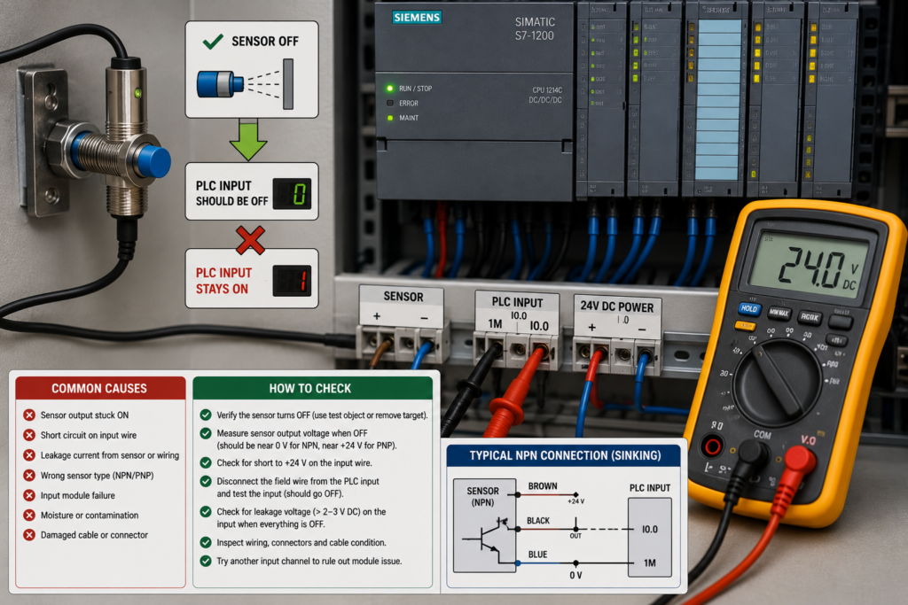
The sensor detects its target correctly. Its indicator light switches off when the target moves away, but the PLC input remains on.
Sometimes it clears after a short delay. Sometimes it stays on until the wire is disconnected. In other cases, the physical input is already off, yet the program still believes the sensor is active.
These symptoms may look identical on the HMI, but they have very different causes.
The fault can be inside the sensor, in the field wiring, at the PLC input module or entirely inside the PLC program. The quickest method is to follow the signal in order:
Sensor output → cable → PLC terminal → physical input address → program logic
First, Identify What Actually Stays On
Compare these four indications:
- Sensor output LED
- PLC input-channel LED
- Physical input address online
- Internal program tag used by the machine
The result immediately narrows the search.
Sensor LED and PLC Input LED Both Stay On
The sensor output may still be active because of incorrect adjustment, an internal off-delay or a failed output transistor.
Sensor LED Turns Off but PLC Input LED Stays On
Current is still reaching the PLC input through leakage, crossed wiring, backfeeding or an incorrect common connection.
PLC Input LED Turns Off but the Program Tag Stays On
The electrical signal is probably healthy. Investigate PLC logic, timers, latches, forcing or communication data.
Do not begin changing input filters until you know which of these situations you actually have.
Step 1: Measure Voltage Directly at the PLC Input
Measure between the affected input terminal and the correct input common.
Take two readings:
- While the sensor is on
- After the sensor switches off
A typical Siemens S7-1200 24V digital input recognises approximately 15V or more as logic 1. The precise switching thresholds and required current depend on the CPU or input module, so check the technical data for the exact part number.
When the sensor is off, the voltage should fall clearly into the module’s logic-0 range.
A reading near the switching threshold may cause the input to remain on or behave unpredictably.
For example:
- 24V normally means a clear ON state
- 0–5V normally means a clear OFF state on many 24V modules
- 8–14V may be an uncertain region, depending on the module
Measure at the terminal rather than relying only on the input LED.
Step 2: Check for Off-State Leakage Current
Electronic sensors do not always behave like completely open mechanical contacts.
A small current can continue flowing through a solid-state sensor output even when the sensor is off. This is known as off-state leakage current. Rockwell Automation warns that excessive leakage can keep a solid-state PLC input active or prevent a small relay from releasing.
This problem is especially common with:
- Two-wire proximity sensors
- Solid-state relays
- Electronic limit switches
- Triac outputs
- Sensors connected in parallel
- Devices containing indicator LEDs
- Outputs with built-in suppression networks
A high-impedance multimeter may show almost 24V even though only a small leakage current is available. What matters is whether that current is high enough to exceed the PLC input’s OFF-state threshold.
Measure both voltage and, where practical, the actual leakage current.
Three-wire sensors usually provide a cleaner PLC interface because their electronics are powered separately from the output signal. Rockwell specifically recommends three-wire sensors for PLC inputs where two-wire leakage creates compatibility problems.
Step 3: Test With a Suitable Load
A temporary, manufacturer-approved test load can help confirm a leakage-current problem.
When a resistor is connected between the input signal and its common, it gives leakage current another path and pulls the input voltage toward the OFF state.
If the input switches off immediately with the test load connected, leakage current is probably the cause.
Do not choose a resistor randomly.
The resistance and power rating must be calculated from:
- Supply voltage
- Sensor leakage current
- PLC OFF-state threshold
- Required resistor power dissipation
PLC manufacturers sometimes publish specific loading-resistor recommendations for particular modules. Using an unsuitable resistor can overload the sensor output or create unnecessary panel heating.
A properly matched sensor or interposing relay is often a cleaner permanent solution.
Step 4: Check the PNP, NPN and Common Wiring
Confirm that the sensor output type matches the PLC input arrangement.
A common three-wire DC sensor uses:
- Brown: +24V
- Blue: 0V
- Black: switching output
However, always verify the sensor diagram instead of relying only on wire colours.
A PNP sensor normally supplies positive voltage to the input when active. An NPN sensor normally pulls the signal toward 0V.
Problems occur when:
- An NPN sensor is connected to a sourcing input arrangement
- A PNP sensor is connected to the wrong common
- Two power supplies do not share the required reference
- The input-group common is connected incorrectly
- The sensor output is connected to the wrong terminal
- Positive and negative conductors are reversed
An incorrect common can allow the input to find a return path through other sensors, indicator lamps or connected equipment.
Measure from the signal terminal to both 0V and +24V. Unexpected voltages often reveal a wiring arrangement that is not what the schematic suggests.
Step 5: Look for Backfeeding From Another Circuit
The input may be receiving voltage from somewhere other than the sensor.
Possible backfeed paths include:
- An indicator lamp
- Another PLC output
- A relay coil
- A shared terminal
- A suppression module
- Parallel sensors
- An HMI-controlled manual circuit
- Incorrectly joined cable cores
- A field-device output powered from another supply
Disconnect the sensor output wire at the PLC terminal.
Input Turns Off
The unwanted voltage is arriving through the field wiring or sensor.
Input Remains On
The fault is likely inside the panel wiring, input module or program.
Reconnect the circuit only after isolating power and following the site procedure.
Step 6: Check for a Stuck or Damaged Sensor Output
A sensor LED switching off does not always prove that its electrical output has switched off.
The LED may indicate target detection while the output transistor remains shorted.
Disconnect the output from the PLC and test it according to the manufacturer’s wiring diagram.
You can also replace the sensor temporarily with:
- A known-good sensor
- A dry contact
- A properly protected test signal
If a dry contact switches the PLC input correctly, but the original sensor does not, the sensor output or its compatibility with the input is suspect.
Also check whether the sensor has configurable functions such as:
- Normally open or normally closed output
- Light-on or dark-on operation
- On-delay
- Off-delay
- One-shot pulse
- Output inversion
- IO-Link switching parameters
Some configurable sensors can intentionally keep their output on after the target disappears. Rockwell IO-Link sensors, for example, support programmed off-delay behaviour in which the output remains active for a selected period after target removal.
Step 7: Inspect the PLC Input Filter
Digital input filters reject brief signal changes.
If an input changes from ON to OFF, the new OFF condition may need to remain stable for the complete configured filter time before the module accepts it.
Siemens describes its input filter as a delay mechanism: a signal change is detected only when it remains present longer than the configured delay.
A filter of a few milliseconds is normal. A larger configured value can make the input appear to remain on briefly after the sensor switches off.
Check the channel properties in the hardware configuration.
Input filtering can explain a predictable short delay. It does not explain an input that remains on indefinitely.
If the input clears after exactly the same period every time, check:
- Hardware input-filter time
- Software debounce timer
- Sensor off-delay
- Remote-I/O filter settings
Step 8: Monitor the Physical Address and Internal Tag Separately
Suppose the PLC input LED turns off and the physical input address becomes false, but the machine logic still shows the sensor as active.
The problem is in the program.
Create a watch table containing:
- Physical input address, such as
%I0.0 - Named sensor input tag
- Internal memory bit
- Timer output
- Sequence-step bit
- HMI status tag
- Final interlock used by the machine
Cross-reference every tag.
Common programming causes include:
- Set/reset latch not being reset
- Off-delay timer
- Debounce logic
- One-shot or pulse-stretch logic
- Internal memory copied only in one program state
- Tag written from more than one block
- HMI command overwriting a memory bit
- Forced input or forced internal tag
- Incorrect normally open or normally closed instruction
- Retentive memory remaining active after restart
A physical PLC input cannot normally be “stuck on” because of an off-delay timer. An internal bit derived from that input certainly can.
Step 9: Check for Forces and Simulation
Online forcing can make a PLC signal remain true regardless of the actual sensor condition.
Check:
- Active force tables
- Forced peripheral inputs
- Simulation values
- Watch-table modifications
- Commissioning overrides
- Temporary maintenance logic
A forced physical input may remain displayed as true even after the terminal voltage disappears.
Remove forces through the approved engineering procedure. Do not assume that restarting the PLC always clears them.
Step 10: Check Remote I/O Communication
When the input belongs to a remote I/O station, loss of communication may leave the program using:
- The last valid input state
- A configured substitute value
- A failsafe value
- Stale data copied into a data block
Check:
- Module status LEDs
- PROFINET or PROFIBUS diagnostics
- Device-reachable status
- I/O update errors
- Quality or validity bits
- Configured substitute-value behaviour
If several remote inputs freeze simultaneously, investigate the I/O connection rather than replacing several sensors.
The HMI may also be displaying an old value because its tag is no longer updating.
Step 11: Inspect the Input Module and Terminal
After eliminating the field device, wiring and logic, test the input channel itself.
Disconnect the field wire and operate the input with a known-good test signal.
If the input remains on with no field wire connected:
- Check for stray wire strands
- Inspect the removable connector
- Verify the input-group common
- Look for moisture or conductive dirt
- Power-cycle the module where permitted
- Move the signal to a spare input channel
If the problem stays with the original channel, the input circuitry may be damaged.
If it follows the field wire to the new channel, continue investigating the sensor and cable.
Fast Troubleshooting Sequence
- Compare the sensor LED, PLC LED and program tag.
- Measure voltage directly from the input terminal to its common.
- Disconnect the sensor output at the PLC.
- Check for off-state leakage current.
- Verify PNP/NPN and common wiring.
- Search for backfeed from other devices.
- Check sensor output configuration and off-delay.
- Review the PLC hardware input filter.
- Monitor the physical address and internal tag separately.
- Check timers, latches and multiple tag writes.
- Remove active forces or simulations.
- Test a spare PLC input channel.
Final Thoughts
When a PLC input stays on after the sensor turns off, do not assume the PLC is faulty.
First determine whether voltage is still present at the physical input terminal. If it is, investigate leakage current, backfeeding, wiring and the sensor output.
If the terminal voltage and physical input are already off, follow the signal into the PLC program. A timer, latch, force or stale communication value is probably keeping the internal condition active.
Follow the signal one stage at a time. Somewhere between the sensor face and the final machine interlock, the ON state stops behaving as expected.
That point is where the real fault is hiding.