A PLC input not working can make a machine look completely dead.
The sensor detects. The button is pressed. The switch changes state. But the PLC does not react.
Sometimes the problem is the sensor. Sometimes it is the wiring. Sometimes it is the input module. Sometimes the input works perfectly, but the PLC program is looking at the wrong address.
That is why troubleshooting PLC inputs should always be done step by step.
Do not guess. Follow the signal.
A PLC input is only one part of the chain. The complete path includes the field device, supply voltage, wiring, common terminal, input module, PLC address, and program logic.
If one part is wrong, the input may not work.
What Is a PLC Input?
A PLC input is a connection point that allows the PLC to receive a signal from a field device.
Typical PLC input devices include:
- Push buttons
- Selector switches
- Limit switches
- Proximity sensors
- Photoelectric sensors
- Magnetic cylinder sensors
- Pressure switches
- Float switches
- Temperature switches
- Relay contacts
- Overload relay contacts
- Safety relay feedback contacts
Most basic PLC inputs are digital inputs.
That means they are either:
- OFF
- ON
Or in logic form:
- 0
- 1
For example, a 24V DC sensor sends voltage to a PLC input. The input module detects this voltage and tells the PLC CPU that the input is ON.
The PLC program then uses that input to make decisions.
How a PLC Input Works
A PLC digital input does not just read a wire magically.
It needs a proper electrical path.
In a typical 24V DC PLC input circuit, the field device sends or switches voltage to the input terminal. The input module detects the signal through its internal electronics. The PLC CPU then stores that input state in memory.
The basic signal path is:
Field device → wiring → PLC input terminal → input module → PLC CPU → program logic
If the signal does not reach the PLC input terminal, the PLC cannot see it.
If the signal reaches the input terminal but the module is wired incorrectly, the PLC may still not see it.
If the PLC sees the input but the program uses the wrong address, the machine still will not react.
That is why input troubleshooting must include both electrical checks and software checks.
Common Symptoms of PLC Input Problems
PLC input faults can show up in several ways.
Common symptoms include:
- Sensor LED turns on, but PLC input LED stays off
- Push button is pressed, but PLC input does not change
- PLC input LED is on, but machine does not respond
- Input works sometimes but not always
- Input flickers
- Input stays on all the time
- Input stays off all the time
- HMI shows wrong sensor status
- Machine sequence stops waiting for an input
- Cylinder does not continue because end sensor is not detected
- Motor does not start because a permissive input is missing
- Alarm appears even though the device looks normal
These symptoms do not all point to the same cause.
The key is to separate the problem into three areas:
- Field device problem
- Wiring or power problem
- PLC module or program problem
Tools Needed for PLC Input Troubleshooting
You do not need many tools to diagnose most PLC input problems.
Useful tools include:
- Multimeter
- Electrical drawing
- PLC software for online monitoring
- Small screwdriver
- Test lamp, if suitable
- Sensor target for testing
- Spare sensor or switch, if available
- Continuity tester
- Insulation tester, only when suitable and disconnected
- Clamp meter, for checking supply circuits if needed
The most important tool is still the multimeter.
PLC software helps you see what the controller thinks.
The multimeter helps you see what is actually happening in the panel.
Use both.
Safety First
Before testing PLC inputs, remember that control panels can contain dangerous voltages.
Even if the PLC input is 24V DC, the same cabinet may contain 230V AC, 400V AC, contactors, drives, and motor circuits.
Basic safety rules:
- Follow lockout/tagout procedures when required
- Do not disconnect wires on live circuits unless trained and allowed
- Use insulated tools
- Know the voltage level before measuring
- Be careful around mixed-voltage terminals
- Do not short input terminals with meter probes
- Check drawings before removing wires
- Never bypass safety devices for normal operation
- Use forcing only with permission and full understanding
Troubleshooting should fix faults, not create new dangerous ones.
Step 1: Check the PLC Input LED
Most PLC input modules have LED indicators.
The input LED usually turns on when the input module detects a valid signal.
This is the fastest first check.
If the field device changes state, watch the input LED.
For example:
- Press the push button
- Move metal near the proximity sensor
- Block the photoelectric sensor
- Manually operate the limit switch
- Change the selector switch position
Then check the input LED.
Possible results:
| Input LED Result | Meaning |
|---|---|
| LED changes correctly | PLC module sees the input signal |
| LED never turns on | Signal may not reach input, common may be wrong, input may be faulty |
| LED always on | Input may be shorted, sensor stuck, wrong logic, or backfeed present |
| LED flickers | Loose wire, unstable sensor, noise, vibration, weak signal |
The LED is not the final answer, but it gives a good direction.
Step 2: Check Online PLC Input Status
The PLC input LED and the PLC program status should match.
Connect with PLC programming software and monitor the input online.
Check whether the input address changes when the field device changes.
For example:
- Sensor wired to I0.3
- PLC online monitor should show I0.3 changing from false to true
If the physical input LED turns on but the online input status does not change, possible causes include:
- Wrong input address
- Wrong module configuration
- Wrong PLC rack or slot
- Hardware configuration mismatch
- Input is on a different module
- PLC not in RUN mode
- Faulted module
- Communication issue between module and CPU
If online input status changes but the machine does not react, the problem is likely in the program logic, not the field input.
Step 3: Check the Electrical Drawing
Before measuring randomly, check the drawing.
You need to know:
- Which device should activate the input
- PLC input address
- Terminal number
- Wire number
- Sensor type
- Voltage level
- Input common group
- PNP or NPN wiring
- Normally open or normally closed logic
- Any intermediate relays or terminals
- Power supply fuse
A good drawing saves time.
A bad drawing makes troubleshooting painful.
If the drawing says the sensor is wired to I0.4, but the PLC program uses I0.5, you have already found a possible problem.
Always compare field wiring, terminal numbers, and PLC software addresses.
Step 4: Check Sensor or Switch Power
If the input is connected to a powered sensor, first check that the sensor has supply voltage.
For a typical 24V DC three-wire sensor:
| Sensor Wire | Function |
| Brown | +24V DC |
| Blue | 0V DC |
| Black | Output signal |
Measure between brown and blue.
Good reading:
| Measurement | Good Reading |
| Brown to blue | Around 24V DC |
Bad readings:
| Reading | Possible Cause |
| 0V | Blown fuse, no supply, broken wire, bad terminal |
| Low voltage | Weak power supply, overload, bad connection |
| Unstable voltage | Loose terminal, failing supply, shorting sensor cable |
If the sensor has no supply voltage, the PLC input will not work.
Do not replace the sensor before checking power.
Step 5: Check the Sensor Output
Once the sensor has power, check whether its output changes.
For a PNP normally open sensor:
Measure black wire to blue wire.
| Sensor State | Expected Reading |
| Not detecting | Around 0V |
| Detecting | Around 24V DC |
For an NPN normally open sensor, the output usually switches toward 0V when active, depending on the input circuit. Testing must be done with the correct reference and input common wiring.
For a simple mechanical switch or dry contact, check whether voltage passes through the contact when it closes.
If the sensor LED changes but the output voltage does not change, possible causes include:
- Wrong output type
- Damaged sensor output
- Sensor overloaded
- Wrong NO/NC logic
- Incorrect test reference
- Broken output wire
- Wrong connector pinout
The sensor detecting and the sensor output switching are not always the same thing.
The LED may show detection, but the output can still be wired wrong or damaged.
Step 6: Measure Voltage at the PLC Input Terminal
This is one of the most important checks.
Do not only measure at the sensor.
Measure directly at the PLC input terminal.
For a PNP 24V DC input, when the sensor is active, you should normally see approximately 24V DC at the PLC input terminal relative to 0V.
For example:
| Test | Good Reading |
| PLC input terminal to 0V, sensor inactive | Around 0V |
| PLC input terminal to 0V, sensor active | Around 24V DC |
If the sensor output has 24V but the PLC input terminal does not, the problem is between the sensor and the PLC.
Possible causes:
- Broken cable
- Loose terminal
- Wrong terminal
- Bad connector
- Damaged wire
- Wrong junction box wiring
- Wrong M12 pinout
- Terminal block issue
If 24V reaches the input terminal but the input LED stays off, check the input common and module type.
Step 7: Check the PLC Input Common
Many PLC input problems are caused by the common terminal.
The input common completes the input circuit.
For many PNP sensor systems:
- Sensor output sends +24V to input
- PLC input common is connected to 0V
For many NPN sensor systems:
- Sensor output switches input to 0V
- PLC input common is connected to +24V
If the common is missing or connected to the wrong polarity, the input may not turn on even though the sensor output changes.
Common-related symptoms:
- Sensor LED turns on, but PLC input LED stays off
- Several inputs in the same group do not work
- Inputs work on one module group but not another
- Input voltage seems correct but module does not respond
- New sensor does not work after replacement
Always check the module wiring diagram.
Do not assume all input modules are wired the same way.
Step 8: Check Input Grouping
PLC input modules often have inputs divided into groups.
For example:
- Inputs I0.0 to I0.7 share one common
- Inputs I1.0 to I1.7 share another common
If one common wire is missing, every input in that group may stop working.
If only one input is not working, the problem may be local to that device or wire.
If a whole group is not working, suspect:
- Missing common
- Blown fuse feeding group
- Loose common terminal
- Module group fault
- Wrong wiring after maintenance
- Broken common jumper
This is a good shortcut during troubleshooting.
One dead input may be one wire.
Eight dead inputs may be one common.
Step 9: Check PNP and NPN Compatibility
A very common fault is installing the wrong sensor output type.
For example:
The original sensor was PNP.
Someone replaces it with NPN.
The sensor powers up. The detection LED works. But the PLC input never turns on.
Why?
Because the output type no longer matches the PLC input wiring.
Check the sensor label or datasheet for:
- PNP
- NPN
- Sourcing
- Sinking
- NO
- NC
- Push-pull
PNP and NPN are electrical output types.
NO and NC are switching logic types.
They are not the same thing.
A sensor can be PNP NO, PNP NC, NPN NO, or NPN NC.
Always match the replacement sensor exactly or confirm compatibility before installing.
Step 10: Check for Wrong Input Address
Sometimes the electrical signal is perfect, but the program uses the wrong input.
This happens during:
- New installations
- Panel modifications
- PLC program changes
- Sensor replacement
- Cabinet rewiring
- Machine upgrades
- Poor documentation
Example:
Sensor is wired to input I0.3.
Program checks input I0.4.
The PLC input LED on I0.3 turns on, but the machine does nothing.
The fix is not a new sensor.
The fix is correcting the wiring, program, or documentation.
Always compare:
- Sensor label
- Terminal number
- PLC input terminal
- PLC address
- Program symbol name
- HMI status
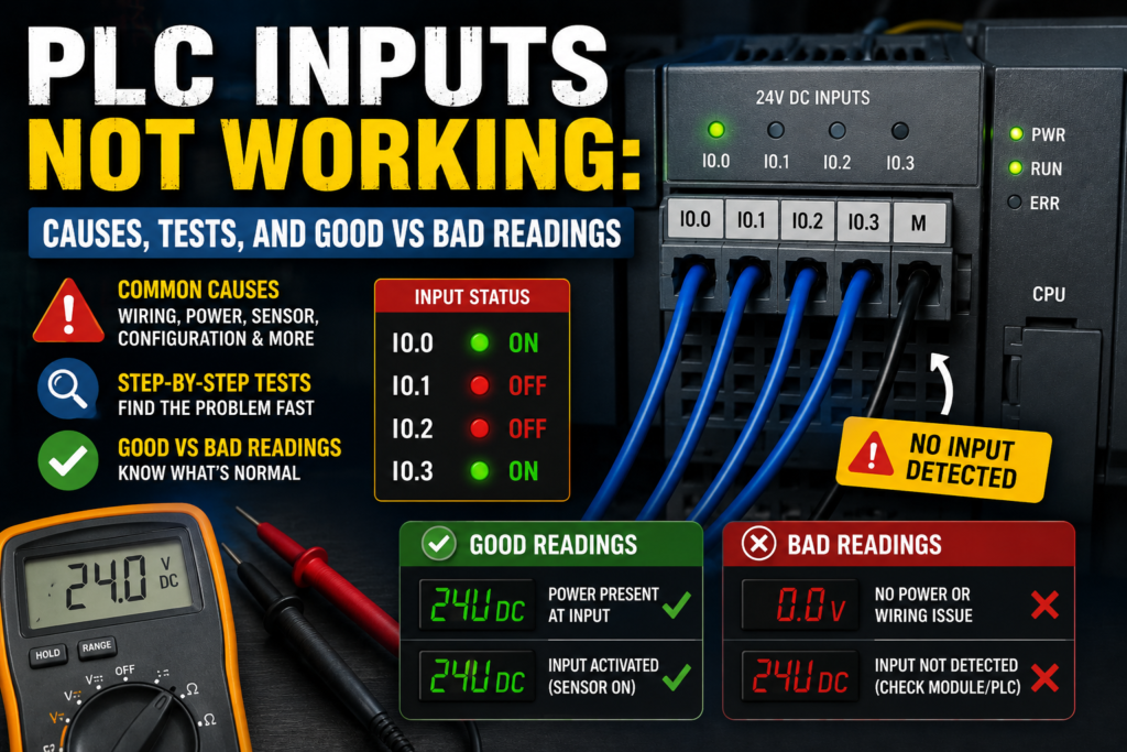
Good Readings for a 24V DC PNP PLC Input
Here is a practical table for a normal PNP sensor connected to a 24V DC PLC input.
| Test Point | Sensor Inactive | Sensor Active | Good or Bad |
| Sensor brown to blue | ~24V DC | ~24V DC | Good |
| Sensor black to blue | ~0V | ~24V DC | Good |
| PLC input terminal to 0V | ~0V | ~24V DC | Good |
| PLC input common to 0V | ~0V | ~0V | Good for typical PNP wiring |
| PLC input LED | OFF | ON | Good |
| PLC online input status | FALSE | TRUE | Good |
If all of these are correct, the input is working electrically.
If the machine still does not react, check the PLC program logic.
Bad Readings for a 24V DC PNP PLC Input
| Bad Reading | Possible Cause |
| Brown to blue = 0V | No sensor supply, blown fuse, broken wire |
| Brown to blue = low voltage | Weak supply, overload, bad terminal |
| Black to blue never changes | Sensor not switching, wrong target, faulty sensor |
| Black to blue always 24V | Sensor stuck on, wrong NO/NC type, short to +24V |
| Sensor output has 24V but PLC input has 0V | Broken signal wire, wrong terminal, bad connector |
| PLC input has 24V but LED off | Missing common, wrong module type, bad input channel |
| LED on but online status false | Wrong address, module configuration issue |
| Online status true but machine does nothing | Program logic, interlock, mode, fault, output problem |
This table solves many real faults.
Use it with your meter.
PLC Input LED ON but Machine Does Not Respond
If the PLC input LED turns on, the input module probably sees the signal.
But that does not mean the machine must react.
Possible causes:
- PLC program uses wrong input address
- Input is not used in the expected logic
- Machine is in manual instead of automatic mode
- Another permissive is missing
- Safety condition is not satisfied
- Fault bit is active
- Timer or sequence condition is blocking operation
- Output is disabled
- HMI status is mapped incorrectly
- PLC is not in RUN mode
At this point, use online monitoring.
Find the input in the program and follow the logic forward.
Which condition blocks the output?
That is the real question.
Sensor LED ON but PLC Input LED OFF
This is one of the most common field problems.
Possible causes:
- Wrong PNP/NPN sensor type
- Wrong input common wiring
- Output wire not connected to PLC input
- Broken black wire
- Wrong M12 pinout
- Sensor output damaged
- Sensor output overloaded
- Wrong input terminal
- Missing field supply to input group
- Input channel damaged
Check in this order:
- Sensor supply voltage
- Sensor output voltage
- Voltage at PLC input terminal
- PLC input common
- Input LED
- PLC input address
If voltage never leaves the sensor output, suspect sensor or output type.
If voltage leaves the sensor but does not reach PLC, suspect wiring.
If voltage reaches PLC but LED stays off, suspect common, input type, or module.
PLC Input Always ON
If a PLC input stays ON all the time, possible causes include:
- Sensor output stuck on
- Wrong sensor logic, NO instead of NC or NC instead of NO
- Signal wire shorted to +24V in PNP circuit
- Signal wire shorted to 0V in NPN circuit
- Moisture in junction box
- Damaged cable
- Backfeed from another circuit
- PLC input forced ON
- Module fault
- Leakage current from two-wire sensor
A useful test is to disconnect the signal wire from the input terminal, only if safe and allowed.
If the input turns off after disconnecting the wire, the issue is probably in the field wiring or sensor.
If the input stays on with the wire removed, check PLC forcing, module fault, or panel wiring.
PLC Input Never Turns ON
If the input never turns ON, possible causes include:
- No sensor power
- Wrong sensor type
- Sensor not detecting target
- Wrong sensing distance
- Broken output wire
- Missing common
- Wrong PLC input group
- Bad input channel
- Wrong input address
- Sensor output overloaded
- Blown fuse
- Loose terminal
- Incorrect connector pinout
Start with the simplest check:
Does the input terminal receive the correct voltage when the device is active?
If no, work backward toward the field device.
If yes, work forward into the PLC module and program.
PLC Input Flickering
A flickering input can be annoying because it may work sometimes and fail randomly.
Possible causes include:
- Loose terminal
- Broken wire inside cable
- Sensor vibration
- Target at edge of sensing range
- Dirty photoelectric sensor lens
- Weak reflector
- Electrical noise
- Cable routed near motor or VFD cables
- Poor grounding
- Unstable power supply
- Input filter too short
- Mechanical switch bounce
Fix depends on the cause.
For mechanical switches, input filtering or debounce logic may help.
For sensors, improve mounting, alignment, sensing distance, cable routing, and shielding.
For electrical noise, separate sensor cables from power cables and check grounding.
Mechanical Switch Input Problems
Not all PLC inputs come from electronic sensors.
Many inputs come from simple mechanical contacts.
Examples:
- Push buttons
- Limit switches
- Selector switches
- Relay contacts
- Overload contacts
For dry contacts, check:
- Contact continuity
- Voltage before and after contact
- Loose terminals
- Worn contact
- Broken actuator
- Mechanical misalignment
- Contact bounce
- Moisture or dirt
- Wrong NO/NC contact used
A limit switch may be electrically good but mechanically not actuated far enough.
A button may click but not close its contact.
A selector switch may have the wrong contact block installed.
Never check only the wire. Check the mechanical action too.
Photoelectric Sensor Input Problems
Photoelectric sensors can fail because of alignment or environmental problems.
Common issues include:
- Dirty lens
- Misaligned reflector
- Wrong light-on/dark-on setting
- Weak reflection
- Object too shiny
- Object too dark
- Background interference
- Sensor saturation
- Loose bracket
- Vibration
- Wrong sensing mode
- Ambient light interference
If the PLC input is not changing, first check the sensor LED and output.
Then verify that the sensor is actually detecting the object reliably.
A photoelectric sensor can look fine until the machine vibrates or dust builds up.
Proximity Sensor Input Problems
Inductive and capacitive proximity sensors also have common issues.
For inductive sensors, check:
- Correct target material
- Sensing distance
- Flush or non-flush mounting
- Metal around sensor face
- Sensor damage
- Cable damage
- Wrong PNP/NPN type
- Wrong NO/NC type
For capacitive sensors, check:
- Sensitivity adjustment
- Material type
- Moisture
- Product buildup
- Sensor contamination
- Mounting distance
- False triggering
If the sensor LED changes correctly but the PLC input does not, the problem is likely electrical.
If the sensor LED does not change reliably, the problem may be sensor setup or application.
Input Module Faults
PLC input modules can fail, but they are not the first thing to blame.
Before replacing the module, check:
- Field voltage
- Common wiring
- Terminal connection
- Sensor output
- Input LED
- PLC configuration
- Program address
- Fuse or power supply
- Connector seating
- Module diagnostics
Signs of a possible bad input channel:
- Correct voltage is present at input terminal
- Common is correct
- Other inputs in same group work
- Input LED does not turn on
- Online status does not change
- Moving wire to spare input works
If one channel is bad, you may be able to move the signal to a spare input and update the program, depending on company rules and documentation.
But document the change properly.
Future troubleshooting depends on it.
PLC Input Forcing
PLC software may allow inputs or internal bits to be forced.
Forcing means the software value is manually held ON or OFF for testing.
This is useful during commissioning, but dangerous if forgotten.
If an input behaves strangely, check whether it is forced.
Symptoms of forcing:
- Online status does not match physical input
- Input appears ON even when field signal is missing
- Machine behaves differently than wiring suggests
- Force table shows active force
- PLC warning LED or software warning appears
Never leave forces active after troubleshooting unless there is a controlled reason and proper procedure.
Forces can make a machine unsafe or confusing.
PLC Input Troubleshooting Flow
Use this simple troubleshooting flow:
- Identify the input address and device.
- Check the electrical drawing.
- Check the device power supply.
- Activate the sensor or switch.
- Check device LED or mechanical operation.
- Measure output voltage at the device.
- Measure voltage at the PLC input terminal.
- Check PLC input common.
- Check PLC input LED.
- Check online PLC input status.
- Check PLC program logic.
- Check output or next sequence step.
This method prevents random guessing.
It also helps you explain the fault clearly to others.
Real Example: Sensor LED ON, PLC Input OFF
Problem:
A proximity sensor LED turns on when metal is present, but PLC input I0.2 stays off.
Checks:
- Brown to blue = 24V DC
- Black to blue when active = 24V DC
- PLC input terminal I0.2 to 0V = 24V DC
- PLC input LED still off
Likely problem:
PLC input common is missing or wired incorrectly.
Fix:
Check the common terminal for that input group. For typical PNP wiring, connect input common to 0V according to the PLC module diagram.
Result:
Input LED turns on and PLC sees the sensor.
Real Example: PLC Input LED ON, Program Not Reacting
Problem:
Input LED on the module turns on when the sensor activates, but the machine sequence does not continue.
Checks:
- Input LED turns on
- Online monitor shows I0.5 active
- Program step is waiting for sensor named “Cylinder_Extended”
- Symbol table shows Cylinder_Extended assigned to I0.6
Likely problem:
Wrong input address in program or wiring.
Fix:
Correct the wiring, address, or symbol assignment after verifying the drawing and machine design.
Result:
Program sees the correct sensor and sequence continues.
Real Example: Input Flickers During Machine Running
Problem:
Photoelectric sensor input flickers when a conveyor motor runs.
Checks:
- Sensor works when motor stopped
- Input flickers when VFD starts
- Sensor cable is routed together with motor cable
- Shield not grounded correctly
Likely problem:
Electrical noise.
Fix:
Separate sensor cable from motor/VFD cable, check shielding and grounding, use proper cable routing, and apply input filtering if needed.
Result:
Input becomes stable.
Best Practices to Prevent PLC Input Problems
Good design prevents many input faults.
Best practices include:
- Use clear I/O documentation
- Label every wire
- Leave spare inputs
- Use correct sensor type
- Standardize PNP or NPN where possible
- Separate signal cables from power cables
- Use shielded cables for noisy or analog signals
- Use proper grounding
- Protect sensor cables mechanically
- Use removable terminal blocks carefully
- Check input common grouping
- Use correct fusing
- Document all changes
- Avoid unnecessary wiring shortcuts
Good panels are easier to troubleshoot.
Messy panels turn simple input faults into long detective stories.
Final Thoughts
When a PLC input is not working, the fault can be in the sensor, switch, wiring, input common, PLC module, addressing, or program logic.
The best method is to follow the signal step by step.
Start at the field device. Check power. Check the output. Measure at the PLC input terminal. Verify the input common. Watch the input LED. Then confirm the online PLC input status and program logic.
For a typical 24V DC PNP sensor, you should see around 24V DC at the PLC input when the sensor is active. If voltage reaches the input but the LED does not turn on, suspect the common or input module. If the LED turns on but the machine does not respond, suspect addressing or program logic.
Do not guess.
Do not replace the PLC first.
Follow the voltage, follow the input status, and follow the logic.
That is how PLC input faults are solved properly.