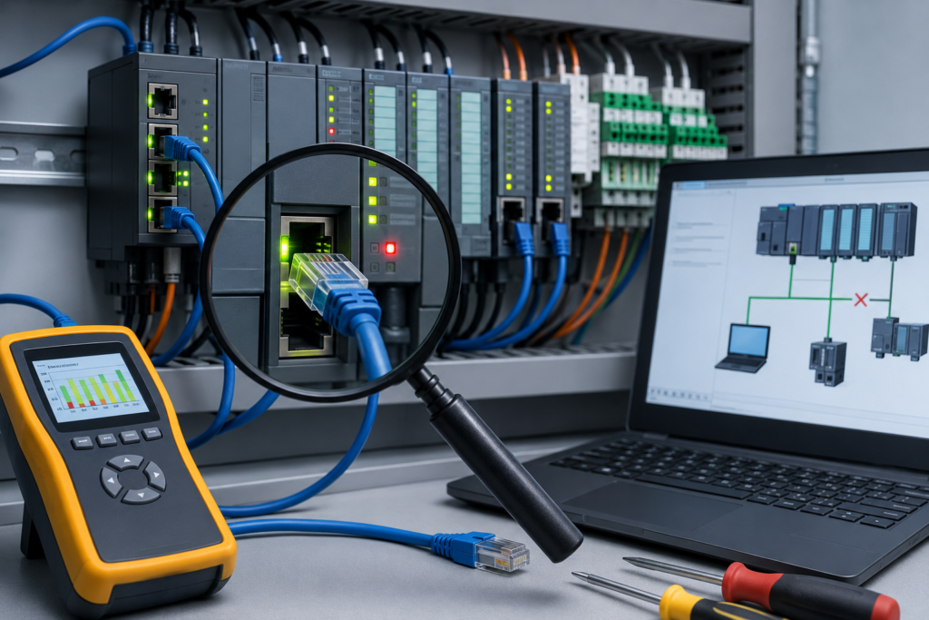
A sensor is clearly blocked, yet the PLC still shows it as OFF.
Or perhaps the opposite problem: the program is commanding a solenoid, the output instruction looks active, but nothing happens in the field.
This is where PLC forcing can be extremely useful. It lets a technician temporarily override an input or output value so that part of the control program can be tested without waiting for the real field condition.
Useful? Absolutely.
Harmless? Not even close.
A poorly considered output force can start a motor, open a valve, release a pneumatic cylinder or bypass part of the machine sequence. Even an input force—which may sound safer—can convince the PLC that a guard, level switch or position sensor is in a state that does not exist physically.
Forcing is therefore not a shortcut for “making the machine work.” It is a controlled diagnostic tool, and it should be treated with the same caution as temporarily bypassing a real electrical signal.
What Does Forcing Mean in a PLC?
Under normal operation, a PLC input value comes from a physical device.
For example:
- A proximity sensor detects a metal part.
- The input module receives 24 V DC.
- The corresponding PLC input becomes true.
- The program reacts to that input.
When the input is forced, the programming software overrides the value seen by the PLC program.
The physical sensor may be OFF, but the program can be made to see the input as ON. Depending on the PLC platform, you may also be able to force the input OFF even while voltage is physically present at the input terminal.
Output forcing works in a similar way.
Normally, ladder logic or another PLC programming language determines whether an output should turn on. When the output is forced, the selected state can override the normal program decision.
That distinction matters:
An input force changes what the program believes is happening.
An output force changes what the PLC commands in the field.
Neither changes physical reality in the way a real sensor or healthy circuit would. A forced input does not repair a broken sensor. A forced output does not prove that the program logic is correct.
It only creates a temporary artificial condition.
Forcing Is Not the Same as Editing a Value
The language used by PLC manufacturers varies, which can make this topic confusing.
Depending on the controller and software, you may encounter terms such as:
- Force
- Override
- Modify value
- Write value
- Set value
- Substitute
- Simulate
- Control value
- Test mode
These functions are not always equivalent.
Changing a normal memory tag may simply write a new value once. The PLC program can overwrite it again during the next scan.
A force usually has greater authority. Once enabled, it may continue holding the selected state regardless of the program logic or physical input condition.
For example, manually writing 1 to a memory bit may last for only a few milliseconds if another instruction writes 0 during every scan. A force may keep the bit at 1 until the force is removed or disabled.
Always understand what the specific PLC platform means by “force” before using it.
Why PLC Forces Are Used
Forcing can save a great deal of troubleshooting time when it is used properly.
Common uses include:
- Testing whether the program responds to an input
- Checking an HMI indication
- Verifying an alarm sequence
- Testing an output module channel
- Commissioning a machine before every sensor is installed
- Confirming communication between a PLC and remote I/O
- Testing an actuator under controlled conditions
- Isolating whether a fault is in the program or field wiring
- Simulating process conditions during offline or controlled testing
Suppose a photoelectric sensor is not changing state.
You force the corresponding PLC input ON and the sequence immediately continues.
That tells you something valuable: the downstream program logic probably responds correctly to the input. The fault is more likely to involve the sensor, wiring, input module, power supply or address assignment.
It does not prove the entire program is correct, but it narrows the search.
That is what forcing is best at—isolating one layer of a problem from another.
How Input Forcing Works
Consider a limit switch connected to a PLC input.
Under normal conditions:
- The switch changes state.
- Voltage reaches or leaves the PLC input terminal.
- The input module updates its status.
- The PLC reads that status.
- The control program uses the input value.
When the input is forced, the controller or programming software substitutes a chosen value for the real input status.
The program may therefore see the input as ON even though:
- The switch is open
- The cable is disconnected
- The input LED is off
- No voltage exists at the terminal
This difference between the physical state and the program state is critical.
A technician looking only at the PLC logic might believe the sensor is functioning. Someone measuring the terminal would see otherwise.
For this reason, forcing must always be documented and clearly communicated to everyone working on the machine.
How Output Forcing Works
An output force can be much more immediately dangerous.
Imagine an output controlling a contactor coil.
The normal PLC program may keep that output OFF because:
- A guard is open
- An overload has tripped
- The machine is not in automatic mode
- A downstream device is not ready
- An emergency-stop circuit is active
- The sequence has not reached the correct step
Forcing the output ON may command the output independently of some or all of that logic.
Exactly what happens depends on the PLC, output module, safety architecture and external wiring. A correctly designed hardwired safety circuit may still prevent dangerous motion—but you should never assume it will.
The force could energize:
- Motor contactors
- Solenoid valves
- Hydraulic valves
- Heaters
- Pumps
- Fans
- Brakes
- Clamps
- Alarms
- Process valves
A small bit on a laptop screen can move a large amount of steel.
That is why output forcing should only be performed by authorized personnel who understand the machine, its stored energy and the consequences of the commanded action.
Setting a Force and Enabling Forces Are Often Separate Actions
Many PLC platforms deliberately make forcing a two-stage process.
First, the technician selects the desired forced state.
For example:
- Force ON
- Force OFF
- Force TRUE
- Force FALSE
At this point, the force may be entered into a force table or marked in the program, but it may not yet be active.
The technician must then enable forces globally.
This extra step is intentional. It reduces the chance of activating a force by accidentally clicking the wrong command.
A typical workflow may look like this:
- Select the input or output.
- Set the desired force value.
- Review the list of pending forces.
- Confirm the machine is safe.
- Enable forces.
- Perform the test.
- Disable forces.
- Remove every force.
- Confirm normal operation.
The exact menu names and behaviour differ between programming packages. Some platforms apply a force immediately. Others separate force installation from force activation.
Never rely on memory when working with unfamiliar software. Check the controller documentation and observe the software’s force indicators carefully.
The Difference Between Disabling and Removing a Force
This catches people out.
Disabling forces and removing forces are not always the same action.
When forces are disabled, the PLC may temporarily stop applying them, but the force definitions can remain stored in the controller or project.
If someone enables forces later, those old force values may become active again.
Removing a force deletes the force assignment itself.
A safe finish therefore normally involves both:
- Disable all forces
- Remove or clear every installed force
Then verify that the controller reports no remaining forced points.
Do not assume that closing the programming software removes forces. It may not.
Do not assume that cycling PLC power removes them either. Some controllers retain forces through power cycles, mode changes or communication loss.
The only safe assumption is that a force remains present until its status has been positively checked.
A Safe PLC Forcing Procedure
No single procedure covers every machine, but the following approach provides a sensible starting point.
1. Understand the Complete Function
Before forcing anything, identify what the signal does.
For an input, determine:
- Which program routines use it
- Which alarms depend on it
- Whether it participates in sequencing
- Whether it affects motion
- Whether it is used as an interlock
- Whether the HMI or another controller reads it
For an output, determine:
- What device it energizes
- What physical movement may occur
- What energy source is involved
- Whether other outputs can operate simultaneously
- Which safety systems remain effective
- Whether the output is direct or routed through another control device
Search for every reference to the tag or address. A signal may be used in more places than the visible ladder rung suggests.
2. Inform Everyone Affected
Tell operators, maintenance staff and other technicians that forcing will be used.
Do not quietly force a signal while another person is inspecting the machine.
Communication should include:
- Which signal will be forced
- What state will be applied
- What equipment may move
- How long the test should last
- Who is controlling the test
- How the test will be stopped
One person should have clear responsibility for enabling and removing the force.
3. Put the Machine in a Safe Condition
Stop production and establish the required safe working condition.
Depending on the task, this may include:
- Selecting manual or maintenance mode
- Clearing personnel from the area
- Removing product from the machine
- Reducing hydraulic or pneumatic pressure
- Applying lockout/tagout
- Disconnecting the actuator
- Opening a downstream control circuit
- Removing mechanical load
- Installing physical restraints
Forcing is not a replacement for lockout/tagout.
If a person may be exposed to hazardous movement or energy, follow the site’s approved isolation procedure before beginning work.
4. Verify the Actual Address
PLC programs often contain similar tag names.
For example:
Conveyor_1_RunConveyor_2_RunConveyor_1_Run_FBConveyor_1_Run_Cmd
Forcing the wrong one can create a completely different result.
Confirm:
- PLC or controller
- Rack
- Module
- Slot
- Channel
- Tag name
- Alias relationship
- Physical terminal
- Device controlled
Use electrical drawings and I/O lists rather than relying only on memory.
5. Check Existing Forces
Before adding a new force, inspect the controller for forces already present.
You may discover:
- A force left from previous maintenance
- A force installed during commissioning
- A forced bit in another routine
- A disabled force waiting to be re-enabled
- A forced signal in remote I/O
Do not enable forces globally until you understand every force that may become active.
This is one of the most important checks in the entire process.
6. Install Only the Required Force
Force the smallest possible part of the system.
Avoid forcing several inputs and outputs at once unless the test has been carefully planned.
The more artificial conditions you introduce, the less clearly the test represents real operation—and the harder it becomes to predict what the machine will do.
7. Use a Second Person for High-Risk Tests
For tests involving motion or significant energy, use a second qualified person where site procedures require it.
One person can monitor the machine while the other controls the software.
Agree on a clear stop command before enabling the force.
A laptop screen does not provide a good view of a cylinder moving behind you.
8. Enable the Force Briefly
Apply the force only for as long as necessary to observe the result.
Watch:
- Physical equipment
- PLC logic
- Module indicators
- HMI status
- Feedback signals
- Current draw
- Pressure or position
- Fault messages
Be prepared to disable the force immediately.
9. Disable and Remove the Force
After the test:
- Disable forces.
- Remove the selected force.
- Check the complete force table.
- Confirm that no forced values remain.
- Return the machine to its normal state.
Do not leave the area until the controller’s force status is understood.
10. Test Normal Operation
After all forces are removed, test the original input or output normally.
Confirm that:
- The physical sensor changes correctly
- The PLC receives the real state
- The output follows the program
- Interlocks operate normally
- Alarms reset correctly
- Automatic operation is restored safely
A successful forced test is not the end of the repair. The real system still has to work.
Never Use Forcing to Bypass Safety Functions
Safety-related signals require special treatment.
Do not use standard PLC forcing to defeat:
- Emergency stops
- Guard switches
- Light curtains
- Safety mats
- Two-hand controls
- Safe-speed signals
- Safety contactor feedback
- Pressure safety switches
- Burner safety devices
- Overtravel limits
Safety PLCs and safety I/O often contain restrictions intended to prevent ordinary forcing. Those restrictions should not be treated as an inconvenience to work around.
Bypassing a safety function may require a formally approved test procedure, risk assessment, additional protective measures and appropriately authorized personnel.
A standard PLC bit showing “guard closed” is not the same as a validated safety input.
Even where the control program uses a non-safety copy of a safety status, forcing that copy can still cause confusing or hazardous machine behaviour.
Input Forces Can Be Dangerous Too
There is a common misconception that forcing inputs is relatively safe because the PLC is not directly turning on an output.
That is not necessarily true.
Suppose you force a “cylinder retracted” input ON. The PLC may then believe that the cylinder has reached a safe position and continue to the next sequence step.
The actual cylinder could still be extended.
The next step might:
- Move another axis into the same space
- Close a clamp
- Start a cutting operation
- Release a workpiece
- Open a process valve
- Start a conveyor
The forced input indirectly causes physical action.
So although input forces do not energize hardware directly, their consequences can travel through the program very quickly.
Always follow the logic forward from the forced condition.
Ask: What will the PLC do when it believes this input is true?
Physically Disconnecting an Output
For some diagnostic tests, disconnecting the field device can reduce risk.
For example, you may want to confirm that a PLC output channel turns on without allowing the connected solenoid valve to move a cylinder.
Depending on the circuit and approved procedure, the field wire may be isolated so the output can be tested electrically while the actuator remains disconnected.
This can be useful, but it is not automatically safe.
Before disconnecting anything:
- Isolate hazardous energy where required
- Confirm the correct conductor
- Check for induced or backfeed voltage
- Secure loose conductors
- Protect against short circuits
- Follow the electrical drawing
- Restore the circuit correctly afterward
Also remember that disconnecting the load changes the electrical conditions. An output LED may turn on successfully even though the output channel cannot supply current to the real device.
A proper test may require measuring voltage under load or using an approved test load.
A Practical Input-Forcing Example
Imagine a conveyor that will not start because the PLC does not detect a box at the loading station.
The input tag is:
Box_Present_PE
The sensor LED is on, but the PLC input remains off.
A controlled diagnostic process could be:
- Confirm the machine is stopped and safe.
- Check the sensor power supply.
- Measure the sensor output voltage.
- Inspect the input-module LED.
- Verify the PLC address.
- Force
Box_Present_PEON. - Observe whether the program advances to the expected state.
- Remove the force immediately.
- Continue troubleshooting the wiring or input channel.
If the program responds correctly to the forced input, the fault probably exists before the program logic—sensor, cable, terminal, module channel or address mapping.
If the program still does not respond, the problem may involve:
- Another interlock
- Incorrect sequence state
- Wrong tag
- Program logic
- HMI mode selection
- A separate permissive condition
The force helped divide the problem into smaller pieces.
A Practical Output-Forcing Example
Suppose a pneumatic valve does not energize.
The output tag is:
Clamp_Extend_Solenoid
The ladder logic never turns the output on because the automatic sequence cannot currently be completed.
Before forcing the output, investigate the consequences.
Ask:
- Will the clamp move immediately?
- Is anyone near it?
- Is air pressure present?
- Could the clamp damage a product or fixture?
- Are both extend and retract solenoids capable of energizing?
- Is there a mechanical obstruction?
- Does another axis occupy the same space?
- Is the valve controlled through a relay or safety circuit?
After creating a safe test condition, the output may be forced briefly while someone observes:
- Output-module LED
- Voltage at the terminal
- Relay operation
- Valve-coil operation
- Pneumatic movement
- Position-sensor feedback
The results help locate the fault.
For example:
| Observation | Possible conclusion |
|---|---|
| PLC output LED turns on, but no terminal voltage | Failed output channel or incorrect wiring |
| Terminal voltage is present, but valve does not operate | Open coil, broken cable, missing neutral/common or mechanical valve problem |
| Valve operates when forced | Field circuit works; investigate program conditions |
| Output cannot be forced | Controller mode, access rights, safety restrictions or software configuration |
| Output turns on, then module faults | Short circuit, overload or damaged field device |
Never leave the forced output active while walking away to inspect another cabinet.
Forcing Internal Tags
Some PLC systems allow internal memory tags to be forced in addition to physical I/O.
Examples include:
- Sequence bits
- Alarm bits
- Mode commands
- Permissives
- Communication flags
- Step numbers
- Calculated status values
Forcing internal logic can be useful during simulation, but it may be harder to predict than forcing a physical input.
An internal tag might be written from several routines, exchanged with another controller or used in dozens of places.
Before forcing it:
- Cross-reference every use
- Check whether it is produced or consumed over a network
- Review aliases
- Examine sequencer logic
- Confirm whether it is safety-related
- Understand how it resets
Sometimes it is safer to simulate the original field input rather than force a deeply embedded program bit.
Forces in Distributed and Networked Systems
Modern PLC systems often exchange data between multiple controllers, remote I/O stations, drives and HMIs.
A value visible in one PLC may originate somewhere else.
For example:
- PLC 1 reads a physical sensor.
- PLC 1 sends the state to PLC 2.
- PLC 2 uses it as an interlock.
- The HMI displays PLC 2’s copy.
Forcing the HMI-visible tag in PLC 2 may not test the real communication path from PLC 1.
Similarly, forcing a produced tag may affect several controllers at once.
Before forcing networked data, determine:
- Where the value originates
- Which controller owns it
- Whether it is produced or consumed
- Which devices subscribe to it
- Whether another program overwrites it
- Whether the force affects only a local copy
Networked systems can turn one apparently small force into a plant-wide signal.
How Forces Are Shown in PLC Software
Most programming systems display a visual indication when forces exist.
You may see:
- A force icon
- A coloured border
- Highlighted tags
- An “F” marker
- A force-status banner
- A warning message
- A toolbar indicator
- A controller status flag
Learn what the indicators mean in the software you use.
The software may distinguish between:
- Force installed
- Force enabled
- Force disabled
- Force active
- Force inhibited
- Force unavailable
Do not assume that a highlighted bit means the same thing on every PLC platform.
A screenshot of the force table can be useful for maintenance records, but it should not replace clearing the forces and verifying the controller afterward.
What Happens During a Power Cycle?
Force behaviour during a power cycle depends on the controller platform, firmware and memory configuration.
Possible behaviours include:
- Forces are cleared
- Forces remain installed but disabled
- Forces remain active
- Force values are restored from nonvolatile memory
- The controller refuses to enter RUN mode
- The controller reports a warning
Because behaviour varies, power cycling should never be used as the normal method of removing forces.
Check the controller directly after power is restored.
The same caution applies to:
- Program downloads
- Controller mode changes
- Communication loss
- CPU replacement
- Memory-card restoration
- Firmware updates
A system should not be returned to production until its force status has been verified.
Common Forcing Mistakes
Forcing the wrong tag
Similar names and copied routines make this easy.
Always confirm the physical address and cross-reference.
Enabling old forces accidentally
A controller may contain forces left from earlier work.
Review all forces before using the global enable command.
Leaving a force installed
The machine works during testing, everyone goes home, and the forgotten force remains.
Later, the machine behaves strangely because the PLC is still seeing an artificial state.
Forcing around an interlock
The interlock may exist because the next movement is unsafe.
Understand why the condition is missing before overriding it.
Testing without watching the equipment
A technician focuses on the laptop while something moves elsewhere.
Use another qualified person or position yourself where the result can be observed safely.
Treating a force as a repair
A forced signal may make the machine run, but the underlying fault remains.
Forcing is diagnostic—not a permanent solution.
Failing to restore wiring
A device is disconnected for testing and never reconnected correctly.
Use labels, drawings and final functional testing.
Forcing several conditions at once
Too many forced values make the program behave in an unrealistic and unpredictable way.
Change one controlled variable at a time.
Why Forgotten Forces Cause Strange Faults
A forgotten force can remain hidden for a surprisingly long time.
Suppose an input indicating “tank level high” is forced OFF during maintenance.
The machine appears normal until the tank fills. The real sensor turns on, but the PLC continues seeing the forced OFF state.
The expected alarm never appears.
Or perhaps a sensor is forced ON. Production runs normally until a different product size is introduced, and suddenly the sequence behaves incorrectly because the PLC believes the part is always present.
These faults are difficult to diagnose because:
- The physical device may be working perfectly
- Wiring measurements appear correct
- The input-module LED may disagree with the program
- The force may have been created weeks earlier
- The original technician may not be present
This is why every forcing job should end with a documented force check.
Not “I think I removed it.”
A proper check.
A Force-Removal Checklist
Before returning the machine to production, confirm the following:
- All forces are disabled
- All installed forces are removed
- No force warning remains in the controller
- Input values match physical device states
- Output values follow program logic
- Disconnected field wiring is restored
- Temporary jumpers are removed
- Guards and covers are replaced
- Safety functions are tested as required
- The machine is tested in manual mode
- Automatic operation is verified
- Operators are informed that testing is complete
- Maintenance records are updated
This final check may take only a few minutes.
It can prevent hours of troubleshooting later—or something much worse.
Better Alternatives to Forcing
Forcing is not always the best testing method.
Depending on the situation, consider:
PLC simulation software
A simulator allows program conditions to be tested without connecting to real machinery.
It is ideal for logic development, sequence testing and training.
Dedicated simulation bits
Some programs include commissioning or simulation logic that safely substitutes selected input conditions.
These modes should be clearly controlled, alarmed and disabled during normal production.
HMI maintenance controls
A well-designed maintenance screen may provide controlled actuator testing with interlocks still active.
This is often safer than directly forcing raw output addresses.
Temporary test equipment
A signal generator, test switch or approved load can help test I/O circuits without manipulating the PLC state.
Online logic monitoring
Sometimes the fault can be found simply by following the sequence and identifying which condition is missing.
No force required.
A good technician does not force because the feature exists. They force only when it provides clear diagnostic value and the risks have been controlled.
PLC Forcing Troubleshooting Table
| Situation | What the result may indicate |
| Forced input advances the sequence | Field sensor, wiring or input channel may be faulty |
| Forced input does not affect the program | Wrong tag, additional interlock or program problem |
| Forced output activates the device | Program conditions may be preventing normal activation |
| Forced output LED turns on but device remains off | Wiring, fuse, common supply, relay or field-device problem |
| Physical input LED is on but forced PLC value is off | Force is overriding the real input state |
| Force cannot be enabled | Controller mode, access level, safety restriction or software issue |
| Force disappears after download | Platform-specific force-clearing behaviour |
| Machine behaves strangely after maintenance | Check for forgotten forces and temporary bypasses |
| Multiple devices move unexpectedly | Forced signal may be used in several routines or controllers |
| Controller warns that forces exist | Inspect and clear the complete force table before operation |
Final Thoughts
PLC forcing is one of the fastest ways to separate a program problem from a field-device problem.
It can show whether a sequence responds correctly, whether an output channel functions and whether the PLC is receiving the condition it expects.
But forcing works by overriding reality.
The sensor may be OFF while the PLC sees ON. The program may demand OFF while the output is commanded ON. That mismatch is exactly what makes forcing useful—and dangerous.
Use the function deliberately. Understand every consequence, create a safe test condition, inform the people around the equipment and keep the test as brief as possible.
Most importantly, clean up afterward.
Disable the forces. Remove them. Verify that none remain. Then prove the machine works using its real sensors, real outputs and normal program logic.
A force should leave no trace behind once the troubleshooting is finished.