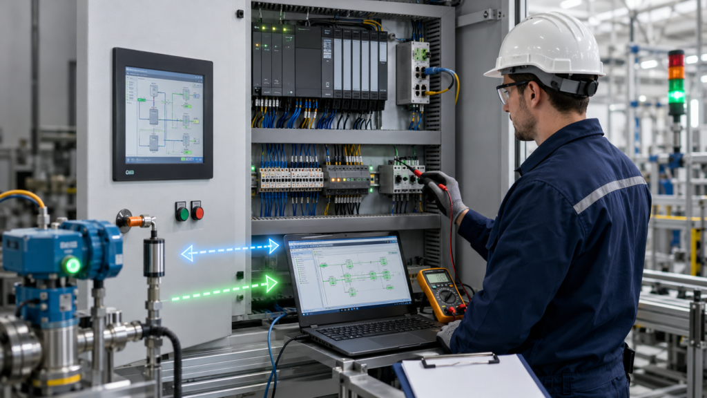
Many PLC commissioning problems are not caused by broken instructions or obvious programming mistakes.
The program compiles. The hardware configuration downloads correctly. Every network appears logical when monitored online. Yet the machine still develops intermittent startup faults, missed transitions or outputs that behave differently under production load.
These problems often originate from timing rather than logic structure.
A practical PLC Logic and Commissioning Suite should help engineers visualize how the controller, remote I/O, HMI and field devices interact over time. Its purpose is not merely to show whether a tag is true or false. It should reveal when the tag changed, when the PLC processed it and whether another system received the same state later.
What the Suite Should Analyze
A useful commissioning toolkit should support several closely related diagnostic areas:
- PLC scan-cycle timing
- Remote I/O communication delay
- HMI polling and stale-data propagation
- Asynchronous input updates
- Race-condition simulation
- Analog filter response
- Startup and recovery sequencing
- Task loading under production conditions
These functions may be implemented through PLC trace tools, diagnostic function blocks, simulation code, event logs or dedicated test screens.
The exact software is less important than the information it provides.
Scan-Cycle Timing Analysis
The first function should show how the PLC executes its program.
Important measurements include:
- Current scan time
- Minimum scan time
- Maximum scan time
- Cyclic-task execution period
- Interrupt-task duration
- Communication loading
- Task overrun events
Average scan time alone is not enough.
A controller may normally complete its scan in 5 milliseconds but occasionally reach 40 milliseconds when communication traffic, diagnostics or complex calculations occur.
Those occasional peaks can explain missed pulses and inconsistent sequence behaviour.
The analysis should also record when relevant inputs become visible to the program and when output commands are transferred to the physical modules.
Remote I/O Delay Analysis
Remote I/O introduces several stages between a physical field event and the PLC response.
A complete signal path may be:
- Sensor changes state.
- Input module detects the change.
- Module filtering processes the signal.
- Remote station prepares updated data.
- Industrial Ethernet transfers the data.
- PLC receives the new input.
- Program logic evaluates the condition.
- Output command is generated.
- Network sends the output to a remote module.
- Actuator responds.
A commissioning suite should compare the timing of these stages wherever possible.
This helps answer questions such as:
- Is the input module filtering the signal?
- Is the network update interval too slow?
- Is the PLC task processing the value late?
- Is the output delay inside the actuator rather than the controller?
Without this breakdown, every delay tends to be described vaguely as a “network problem.”
Stale HMI Data Detection
An HMI is not a direct representation of every PLC scan.
The controller may execute hundreds of cycles between two HMI updates. Short events can therefore appear and disappear without ever reaching the screen.
A useful diagnostic system should display:
- PLC tag value
- HMI-visible value
- Last PLC update time
- Last HMI refresh time
- Data-valid status
- Communication quality
- Age of the displayed value
This is especially important for analog measurements.
A pressure value may remain at 4.8 bar after communication has stopped. The number still looks believable, but it is no longer current.
Important tags should therefore include validity information rather than being displayed as isolated numbers.
Race-Condition Simulation
Race conditions occur when the final result depends on the order or timing of nearly simultaneous events.
For example:
- A start request and stop request arrive together.
- A sequence-complete bit becomes true during the same scan as a timeout.
- An operator resets a fault while the fault condition is still active.
- Local and remote sensors update during different scans.
- Two program blocks write to the same command.
A race-condition simulator should allow these events to be introduced with adjustable timing differences.
Instead of testing only:
- Input A first
- Input B second
the test should also try:
- A and B in the same scan
- B before A
- A one scan before B
- A local while B is delayed through remote I/O
- Both changing during a task interruption
The goal is to identify whether the result changes unexpectedly.
A deterministic program should have defined priorities regardless of which non-critical event arrives first.
Analog Filter Delay Analysis
Filtering makes analog values smoother, but every filter adds delay.
The commissioning toolkit should compare:
- Raw sensor value
- Module-filtered value
- PLC-filtered value
- Controller process value
- HMI-displayed value
These values should be recorded on the same timeline.
This reveals whether a clean HMI trend is hiding rapid process movement.
For example, actual pressure may fall below the shutdown threshold immediately, while the heavily filtered value takes several seconds to cross the same limit.
The PLC logic may be correct, but the interlock reacts late because it is using a delayed signal.
The analysis should help determine whether the filter is removing noise or removing useful process visibility.
Startup Sequence Validation
Startup is one of the most timing-sensitive phases of machine operation.
Different components become ready at different speeds:
- PLC CPU
- Safety controller
- Remote I/O
- VFDs
- Servo drives
- Pneumatic pressure
- Intelligent sensors
- HMI communication
- External controllers
A startup validator should test several combinations rather than assuming a fixed order.
Possible tests include:
- Remote I/O connects late.
- One drive remains unavailable.
- Safety resets before field devices are ready.
- Pressure becomes healthy briefly and then drops.
- The operator presses START too early.
- Communication disappears during initialization.
- Power returns while equipment is not in its expected position.
Each test should produce a clear and recoverable machine state.
The program should not proceed simply because all permissives appeared true for one scan. Critical readiness conditions may need to remain stable for a defined period.
Recommended Diagnostic Workflow
A structured workflow prevents technicians from changing logic before understanding the fault.
1. Analyze Scan Timing
Begin by recording the actual PLC cycle and task behaviour under live operating conditions.
Check maximum scan time, not only the current value.
Identify one-scan pulses, interrupt activity and any tasks that occasionally exceed their expected execution time.
2. Record the Full Signal Chain
Do not monitor only the final output command.
For a machine sequence, record:
- Raw physical input
- Remote I/O status
- PLC process-image input
- Filtered input
- Interlock result
- Current sequence step
- Transition command
- Output request
- Physical output feedback
- Device response
This allows the first unexpected change to be identified.
3. Validate Startup Asynchronously
Introduce delays deliberately.
Allow the PLC to start before the drives. Delay a remote station. Restore communication while the machine is in an unusual position.
A strong startup sequence should wait for valid conditions or enter a specific recovery state.
4. Simulate Race Conditions
Test conflicting and simultaneous events.
Verify that:
- Stop overrides start.
- Active faults override reset.
- Safety conditions override normal control.
- Only one sequence transition can occur.
- Multiple tasks do not write conflicting values.
- Communication handshakes cannot be missed.
Program order should not create an accidental operating priority.
5. Compare Raw and Filtered Signals
Inject realistic analog changes and record the response.
Measure how long it takes for:
- Raw input to change
- Filtered value to respond
- Interlock threshold to be crossed
- Controller output to react
- HMI trend to display the change
Reduce filtering when the process delay becomes unacceptable.
6. Test Remote I/O Under Load
Perform testing while the real network is active.
Include:
- HMI communication
- Drive telegrams
- Engineering-station access
- Normal production traffic
- Diagnostic requests
- Other controllers
A sequence that works on an unloaded test network may behave differently when all communication is active.
7. Verify Fault Recovery
Do not stop testing after confirming that a fault is detected.
Check what happens after:
- Fault acknowledgement
- Communication restoration
- Sensor recovery
- Emergency-stop reset
- Power restoration
- Manual intervention
The machine should return to a defined state rather than resuming from an ambiguous sequence condition.
Useful Diagnostic Features
A practical PLC commissioning library may include several reusable function blocks.
Event timestamp block
Records when a condition changed and whether it was rising or falling.
First-out fault recorder
Stores the first failed permissive before secondary alarms appear.
Signal age monitor
Measures how long it has been since communication data changed or was confirmed valid.
Scan-time recorder
Stores current and maximum cycle times during the production cycle.
Sequence history buffer
Records previous sequence states and transition reasons.
Race-condition test block
Introduces configurable delays or simultaneous command combinations during controlled testing.
Analog comparison block
Records raw, filtered and displayed process values together.
Communication watchdog
Confirms that remote data continues to update rather than simply retaining its last value.
These tools should support troubleshooting without becoming permanent hidden logic that changes normal machine operation.
Expected Benefits
A structured commissioning suite can improve both troubleshooting speed and machine reliability.
The expected benefits include:
- More accurate fault diagnosis
- Faster identification of timing problems
- Reduced intermittent startup failures
- Better visibility of stale communication data
- Safer online commissioning
- Fewer unnecessary program changes
- Improved remote I/O troubleshooting
- More reliable recovery after faults
- More deterministic control behaviour
It also improves communication between programmers, electricians and operators.
Instead of saying, “The motor sometimes fails to start,” the commissioning team can report:
The drive-ready signal reaches the PLC 180 milliseconds after the startup transition is evaluated.
That is a fault that can be corrected.
Avoid Turning Diagnostics Into More Complexity
A commissioning suite should simplify fault analysis, not bury the machine program under hundreds of undocumented test bits.
Diagnostic functions should use:
- Consistent naming
- Clear enable conditions
- Defined memory limits
- Documented timestamps
- Separate commissioning and production modes
- Controlled reset behaviour
Simulation functions that force delays or modify signals must be disabled securely before normal production.
The diagnostic layer should observe the machine wherever possible rather than changing its behaviour.
Final Thoughts
PLC commissioning becomes much easier when timing is treated as measurable data rather than guesswork.
Scan cycles, remote I/O updates, HMI polling, analog filtering and asynchronous devices all operate at different rates. A logic network can be structurally correct and still fail because one signal arrived earlier or later than expected.
A well-designed PLC Logic and Commissioning Suite makes those relationships visible.
The objective is not to build the most complicated diagnostic system. It is to answer three practical questions:
- What changed first?
- When did the PLC process it?
- Why did the program choose its final state?
Once those answers are available, intermittent faults stop looking random.