The ladder logic says the output is ON. The output-module LED is glowing. Yet the solenoid, contactor, lamp or valve in the field does absolutely nothing.
At first glance, that makes the PLC look guilty. In reality, an illuminated output LED only confirms that the controller is commanding the channel. It does not prove that power is leaving the terminal, reaching the field device or producing mechanical movement.
The fault may still be in the output module, but wiring, fuses, overloads and failed loads are usually more common.
Start With the PLC Program
Before opening the cabinet, confirm that the correct output is active in the PLC program.
Check the output tag, rack, slot and channel. Similar tag names can cause confusion, especially on machines with repeated stations.
Also check whether:
- The output is being forced
- Another routine writes to the same tag
- The module is inhibited
- The PLC is in RUN mode
- The output is being pulsed too quickly to observe
If the program command is genuinely ON and the physical output LED is also ON, move to the electrical circuit.
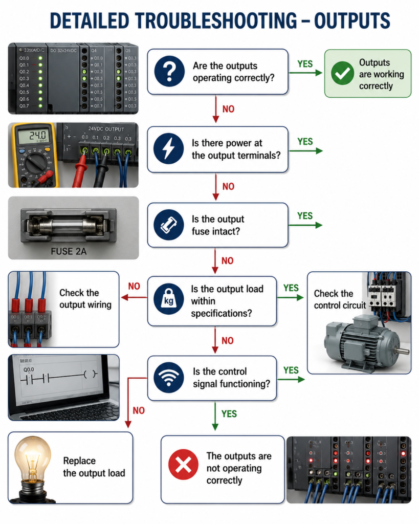
Check for Voltage at the Output Terminal
Use a properly rated multimeter and measure directly at the output-module terminal.
Measure relative to the correct common or neutral point. Measuring against the wrong reference can create misleading results.
If the expected voltage is present, the PLC output is probably operating. Continue tracing the circuit toward the device.
If there is no voltage, check:
- Output-module supply
- Channel or group common
- Output fuse
- Terminal connection
- Module configuration
- Failed output channel
Some output modules are divided into groups, and each group may require its own external supply. The module LED can still illuminate even when the field-side supply is missing.
Inspect the Output Fuse
Many PLC output circuits use external fuses to protect the module and wiring.
A blown fuse may be caused by:
- Shorted solenoid coil
- Damaged cable
- Incorrect field wiring
- Excessive load current
- Wrong replacement device
- Accidental short during maintenance
Do not simply replace the fuse and restart the machine.
First inspect the downstream circuit. If the fault remains, the new fuse may blow immediately—or the output module may suffer damage if oversized protection is installed.
Always replace a fuse with the correct type and rating.
Trace the Output Wiring
Follow the circuit from the PLC terminal to the field device.
Check:
- Terminal strips
- Plug connectors
- Junction boxes
- Interposing relays
- Safety contacts
- Motor overload contacts
- Local disconnects
- Broken conductors
- Loose screws
A loose terminal may carry enough voltage for a meter to detect but fail once the load tries to draw current.
This is why measuring voltage under operating conditions is important. A circuit may show 24 V with the load disconnected and collapse to almost zero when the solenoid is energized.
Pay special attention to moving cables, machine doors and cable chains. Internal conductors can break while the outer insulation still looks fine.
Check Interposing Relays and Contactors
The PLC output may not operate the final device directly.
It may energize an interposing relay, which then supplies power to a contactor or solenoid.
If the PLC output is ON, check whether the relay coil energizes.
Look for:
- Relay indicator LED
- Audible click
- Coil voltage
- Burned contacts
- Loose relay socket
- Incorrect relay voltage
- Mechanical sticking
A relay can click normally while its contacts remain burned or open.
For motor circuits, also inspect the contactor and overload relay. A tripped overload or open auxiliary contact can prevent the motor from starting even though the PLC output circuit is healthy.
Confirm the Output Type Matches the Load
PLC output modules may use:
- Relay outputs
- Transistor outputs
- Triac outputs
Each has different characteristics.
Relay outputs can switch AC or DC loads within their ratings, but mechanical contacts eventually wear.
Transistor outputs normally switch DC and may be sourcing or sinking.
Triac outputs are generally designed for AC loads and may allow a small leakage current when switched off.
Check that the module matches the load voltage, current and switching requirements.
An oversized contactor coil, valve bank or lamp load may exceed the channel rating. Inductive loads should also use appropriate surge suppression, such as a flyback diode, RC snubber or varistor, depending on the circuit.
Without suppression, repeated voltage spikes can damage the output channel.
Test the Field Device Independently
Once it is safe and permitted, test the field device separately from the PLC output circuit.
For example, a solenoid coil can be checked for:
- Correct supply voltage
- Coil resistance
- Open winding
- Short circuit
- Mechanical valve movement
A contactor coil can be energized using an approved test method.
Do not apply power blindly. Confirm the correct voltage, polarity and expected machine movement first.
If the device works independently but not from the PLC circuit, focus on:
- Output module
- Fuse
- Relay
- Wiring
- Common connection
If the device still does not work with the correct direct supply, the device itself is probably faulty or mechanically jammed.
Suspect the Output Module Last
An output channel can fail, especially after a short circuit or overload.
Possible signs include:
- Output LED is ON but no terminal voltage
- One channel fails while others work
- Channel faults repeatedly under load
- Burn marks or unusual smell
- Output remains permanently ON
- Module diagnostic fault
Where practical, move the circuit to a known working spare channel and update the program carefully.
If the fault stays with the original channel, the module may be damaged.
If the fault follows the field wiring, keep looking downstream.
Quick Troubleshooting Sequence
When the output LED is ON but the device remains OFF:
- Confirm the correct PLC output command.
- Measure voltage at the output terminal.
- Check the output supply and common.
- Inspect fuses and overloads.
- Trace wiring toward the field device.
- Test relays and contactors.
- Confirm the output type matches the load.
- Test the device independently.
- Replace the output module only after proving the channel has failed.
Final Thoughts
A PLC output LED is useful, but it is only one point in the circuit.
The complete signal path is:
PLC logic → Output module → Fuse → Wiring → Relay or contactor → Field device
Troubleshooting becomes much easier when each stage is tested in order.
Do not replace the PLC module merely because the device is not moving. A blown fuse, missing common, loose terminal or failed solenoid is often the real cause.
Follow the voltage, test under load and change one thing at a time.
That usually finds the fault faster—and with far fewer expensive parts left on the workbench.