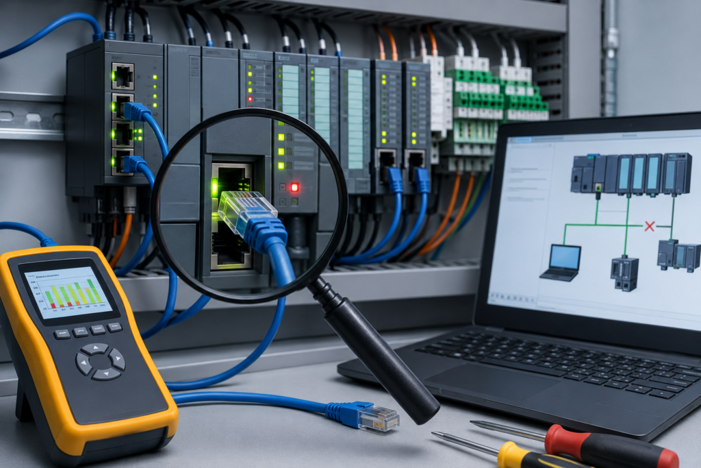
The machine is stopped. Operators are waiting. Production wants an answer, preferably five minutes ago.
That is exactly when people start clicking random buttons, changing several things at once and restarting equipment without first checking what caused the problem.
Sometimes the machine comes back.
Sometimes the original evidence disappears and a fairly ordinary fault turns into a two-hour guessing game.
A reliable PLC troubleshooting workflow is not about knowing every menu inside the programming software. It is about following a repeatable sequence: make the equipment safe, understand the complaint, connect to the correct controller, preserve the running program, inspect diagnostics and then follow the logic until the real field condition no longer matches what the PLC expects.
The order matters.
Start With the Machine, Not the Laptop
Before opening programming software, look at the actual machine.
Ask the operator what happened.
Useful questions include:
- What was the machine doing when it stopped?
- Did it stop suddenly or finish the current cycle?
- Was there an unusual noise?
- Did any breaker or overload trip?
- Did the HMI show an alarm?
- Has this happened before?
- Was anything repaired or adjusted recently?
- Does the fault occur with one product or recipe?
- Can it be reproduced?
Operators often know the machine’s normal behaviour extremely well. They may not use engineering language, but comments such as “it always stops when that cylinder comes back” or “the screen freezes whenever the large motor starts” are valuable clues.
Do not ignore them.
At the same time, do not accept the first description as a confirmed diagnosis. “The PLC is broken” may eventually turn out to mean that a 24 V DC fuse has opened.
Make the Equipment Safe
Troubleshooting does not make the machine harmless.
A stopped machine may still contain:
- Electrical energy
- Pneumatic pressure
- Hydraulic pressure
- Suspended loads
- Hot surfaces
- Stored spring force
- Rotating components
- Unexpected automatic restart conditions
Follow the site’s approved safety procedures.
Depending on the work, this may include:
- Stopping the machine
- Selecting manual or maintenance mode
- Informing nearby personnel
- Applying lockout/tagout
- Releasing stored pressure
- Supporting suspended components
- Confirming that automatic restart is prevented
- Establishing controlled access to the work area
Going online with the PLC is not automatically dangerous. Changing logic, forcing outputs or testing motion certainly can be.
Know which stage of troubleshooting you are entering before you begin.
Take a Quick Visual Snapshot
Before resetting anything, record what the machine is showing you.
Look at:
- PLC status LEDs
- Remote I/O indicators
- HMI alarms
- Drive fault codes
- Safety relay LEDs
- Communication-module indicators
- Power-supply voltage indicators
- Tripped breakers
- Overload relays
- Blown fuse indicators
- Sensor LEDs
- Switch port link lights
Take photographs or screenshots when site rules allow it.
This takes less than a minute and may preserve the most useful evidence available.
After a reset or power cycle, those LEDs may return to normal and the fault history may become harder to interpret.
The Basic PLC Troubleshooting Workflow
A practical workflow can be reduced to six main stages:
- Establish communication with the PLC.
- Upload and save the program currently running.
- Go online and monitor the live program.
- Review active faults and diagnostic history.
- Test individual conditions carefully.
- Document the cause, repair and final result.
That sounds simple. The difficulty lies in doing each step properly rather than rushing toward the first suspicious-looking rung.
Step 1: Connect to the Correct PLC
First, confirm that your laptop can actually communicate with the controller.
Depending on the system, the connection may use:
- Ethernet
- USB
- Serial communication
- MPI or PROFIBUS
- PROFINET
- EtherNet/IP
- A manufacturer-specific programming cable
- A remote engineering connection
Check the obvious items first:
- Is the PLC powered?
- Is the communication cable connected?
- Are Ethernet link lights active?
- Is the laptop using the correct network adapter?
- Are the laptop and PLC on compatible IP subnets?
- Is a VPN changing the routing?
- Is the correct communication driver selected?
- Is the controller visible in the manufacturer’s discovery tool?
For an Ethernet-connected PLC, verify the laptop address.
Suppose the controller uses:
- IP address:
192.168.10.20 - Subnet mask:
255.255.255.0
A temporary laptop address might be:
- IP address:
192.168.10.100 - Subnet mask:
255.255.255.0
The final number must be unique.
Test basic communication with:
ping 192.168.10.20A successful ping confirms basic IP connectivity, but it does not prove that the programming software is configured correctly. A firewall, wrong driver or controller access setting may still block the engineering connection.
Make Sure You Are Connecting to the Right Controller
Factories often contain similar machines with similar PLC names and nearly identical IP addresses.
Before uploading or changing anything, verify:
- Machine name
- Controller name
- IP address
- PLC model
- Serial number, where available
- Rack and slot
- Project name
- Physical location
Do not rely only on a device appearing first in a network scan.
Connecting to the wrong machine is embarrassing. Downloading to it is much worse.
Step 2: Upload the Program Currently Running
Once communication is established, preserve a copy of what is actually inside the PLC.
This is important even when a project file already exists on the maintenance laptop.
The saved project may be:
- Outdated
- Missing recent changes
- Created for a different machine
- Based on another firmware revision
- Missing current tag values
- Missing online comments
- Incorrectly labelled
- Modified without being downloaded
Upload the current controller program where the PLC platform supports it.
Save the file before making changes.
A useful filename includes:
- Machine name
- Date
- Time
- Whether it is before or after troubleshooting
- A short reason
For example:
Packaging_Line_2_2026-07-22_Before_FaultfindingThat is far more useful than:
Final_New_Copy_3Future technicians should not need detective training merely to find the correct backup.
Upload Versus Download
These two terms are easily confused.
In most PLC environments:
Upload means transferring the program from the PLC to the computer.
Download means transferring the project from the computer to the PLC.
Some software packages use different wording, so always read the confirmation window before proceeding.
Uploading normally preserves the controller’s current program.
Downloading may replace it.
Never click through a transfer window out of habit. Confirm the direction.
Compare the Online and Offline Projects
If you already have an engineering project, compare it with the controller before deciding which version is authoritative.
Check:
- Program logic
- Hardware configuration
- Tags
- Communication settings
- Safety signatures
- Firmware revision
- Motion settings
- Recipe values
- Comments and documentation
- Last modified dates
An online mismatch warning should not be ignored.
Sometimes the difference is harmless, such as a comment change. Other times it means that the PLC contains logic no one has backed up.
Preserve both versions until the difference is understood.
Step 3: Go Online and Monitor the Program
Once the running program is safely backed up, go online.
Online monitoring lets you observe:
- Input states
- Output states
- Internal bits
- Sequence steps
- Timers
- Counters
- Analogue values
- Alarm conditions
- Communication status
- Interlocks and permissives
This is where PLC troubleshooting becomes powerful.
Instead of guessing why the machine will not continue, you can watch the exact condition preventing the next action.
Begin With the Alarm or Stopped Function
Start from the machine symptom.
For example:
- Conveyor will not start
- Cylinder will not extend
- Pump stops after five seconds
- Robot is not receiving a start command
- HMI shows “station not ready”
- Motor contactor output never turns on
Find the relevant output command, sequence bit or alarm in the PLC program.
Then work backward.
If the conveyor output is OFF, determine which condition on the rung is false.
Possible conditions may include:
- Automatic mode active
- Emergency stop healthy
- Motor overload healthy
- Guard closed
- Downstream conveyor ready
- Product sensor active
- Start request present
- No active fault
- Correct sequence step
Do not jump straight to the output module.
The PLC may be correctly refusing to energize it because one permissive is missing.
Follow the Logic Backward
A good rule is:
Start at what should be happening and trace backward until the expected condition and the actual condition stop matching.
Suppose a cylinder should extend, but its solenoid output is OFF.
The output instruction may depend on:
- Step 30 active
- Guard circuit healthy
- Cylinder retracted sensor ON
- Air pressure OK
- No opposing solenoid active
- Cycle stop not requested
If the cylinder retracted sensor is OFF, inspect that signal.
Then determine:
- Is the cylinder physically retracted?
- Is the sensor LED on?
- Is voltage present at the input?
- Is the PLC input-module LED on?
- Is the correct tag assigned?
- Is the input being forced?
- Is the input inverted in software?
The ladder logic tells you where to investigate. Measurements confirm what is happening in the field.
Use both.
Understand Normal PLC Scan Behaviour
While monitoring logic, remember that the PLC executes its program repeatedly.
A simplified scan includes:
- Reading inputs
- Executing the program
- Updating outputs
- Performing communication and diagnostics
- Repeating the cycle
This can happen thousands of times per second.
Signals that change very quickly may be difficult to observe in ordinary ladder monitoring. The software display refreshes much more slowly than the PLC executes.
A bit may turn on for 20 milliseconds and disappear before you ever see it highlighted.
For fast events, use:
- Trend tools
- Watch tables
- Latching diagnostic bits
- Event counters
- Timestamps
- Sequence-history buffers
- Oscilloscope or logic analyser where appropriate
Do not assume a signal never changed merely because you did not see it change on screen.
Use Cross-References
When you find a suspicious tag, cross-reference it.
This reveals every place where the tag is:
- Read
- Written
- Reset
- Set
- Moved
- Aliased
- Produced
- Consumed
- Used in calculations
- Passed to a function block
A tag may look OFF because another routine resets it every scan.
An output command may be written from multiple locations.
A sequence value may be overwritten by a fault routine.
Without cross-references, it is easy to stare at the wrong instruction and miss the logic controlling it elsewhere.
Use Watch Tables and Data Monitors
A watch table allows several related values to be observed together.
For a conveyor problem, you might monitor:
- Start request
- Auto mode
- Safety healthy
- Overload feedback
- Upstream ready
- Downstream ready
- Motor command
- Motor running feedback
- Fault timer
- Active sequence step
This gives a much clearer picture than jumping between ten separate routines.
Watch tables are particularly useful when troubleshooting:
- Intermittent faults
- Sequence problems
- Communication failures
- Analogue limits
- Drive control
- Recipe-dependent problems
- Motion sequences
Arrange values in the order the process should occur.
Then watch where the expected sequence breaks.
Step 4: Check Active Faults and Fault History
Do not focus only on ladder logic.
Open the controller diagnostics and inspect both current faults and previous events.
Depending on the PLC platform, useful areas may include:
- Controller properties
- CPU diagnostics
- Diagnostic buffer
- Major fault history
- Minor fault log
- Module information
- Communication status
- Hardware diagnostics
- Safety diagnostics
- Motion fault history
Record the exact code and description.
A statement such as “PLC faulted” is not enough.
A useful record includes:
- Fault code
- Fault class
- Fault description
- Timestamp
- Affected module
- Slot or node
- Program or task
- Controller operating mode
- Events immediately before the fault
The earliest relevant event is often more valuable than the final fault.
For example:
- Ethernet adapter disconnected.
- Remote I/O connection failed.
- Position feedback was lost.
- Sequence timer expired.
- Machine fault became active.
The timer alarm is real, but it is not the root cause.
Major and Minor Faults
A major fault may stop the controller or place it into a faulted state.
Common examples include:
- Watchdog timeout
- Division by zero
- Invalid array reference
- Critical hardware failure
- Program corruption
- Required I/O mismatch
- Memory error
A minor fault or warning may allow the controller to continue running.
Examples include:
- Temporary communication loss
- Recoverable module warning
- Battery warning
- Time synchronization error
- Optional device unavailable
- Noncritical instruction error
Minor faults still matter.
Repeated communication warnings, for example, may be the first sign of a damaged cable, unstable power supply or failing switch port.
Check Module Diagnostics
If the controller reports an I/O or network fault, inspect the individual module.
The CPU may only report that a connection has failed. The module may reveal:
- Channel short circuit
- Wire break
- Missing field supply
- Configuration mismatch
- Incorrect firmware
- Temperature warning
- Connection timeout
- Module ownership conflict
- Wrong electronic keying
- Device name mismatch
The more specific diagnostic is usually closer to the root cause.
Step 5: Verify the Physical Inputs and Outputs
PLC software only shows what the controller believes.
You still need to inspect the real machine.
For a digital input, compare:
- Physical device condition
- Sensor indicator LED
- Measured sensor output voltage
- PLC input-module LED
- Online input tag
These five points should agree.
If the sensor LED is on but no voltage reaches the input terminal, suspect wiring.
If voltage reaches the terminal but the module LED remains off, suspect the module channel, common connection or configuration.
If the module LED is on but the PLC tag is off, check address mapping, aliases, forcing and software configuration.
This layer-by-layer comparison is far more effective than replacing parts at random.
Verify Output Circuits in Stages
For an output that does not operate, inspect:
- Program output command
- PLC output-module indicator
- Voltage at the output terminal
- Interposing relay or contactor
- Field wiring
- Device coil
- Mechanical response
- Feedback sensor
Suppose the program command is ON and the module LED is ON, but no voltage exists at the output terminal.
Possible causes include:
- Failed output channel
- Missing output common
- Blown fuse
- Incorrect module wiring
- Module fault
If voltage reaches the solenoid but it does not operate, the problem is probably outside the PLC:
- Open coil
- Jammed valve
- Low air pressure
- Mechanical obstruction
- Incorrect voltage
- Damaged cable
- Broken connector
The PLC is often blamed simply because it is visible on the laptop.
Quite often, it is doing exactly what it should.
Step 6: Use Forces Only When Necessary
Forcing can help isolate a field fault from a program fault.
For example, forcing an input may show whether the downstream sequence responds correctly.
Forcing an output may help test a field circuit.
But forces override normal conditions, and that can create unexpected movement.
Before forcing anything:
- Understand every use of the tag
- Make the machine safe
- Inform affected personnel
- Review existing forces
- Confirm the correct address
- Understand what equipment may move
- Keep the test brief
- Be ready to disable the force immediately
Never use ordinary forcing to bypass safety devices or defeat approved safety logic.
A forced input can be dangerous too. Forcing “cylinder retracted” may allow another axis to move into the same space even though the cylinder is still extended.
The PLC reacts to what it sees, not what is physically true.
Disable and Remove Forces After Testing
Disabling forces and removing them may be separate operations.
A disabled force can remain installed and become active again if someone later enables forces globally.
After testing:
- Disable forces.
- Remove every installed force.
- Review the full force list.
- Confirm no force warning remains.
- Test the real input or output normally.
- Document the test.
Do not rely on closing the software or cycling PLC power to clear forces.
Controller behaviour varies.
Check it directly.
Change One Thing at a Time
This rule saves enormous amounts of time.
If you replace a sensor, move the cable to another terminal, edit the logic and restart the PLC all at once, you may restore operation—but you will not know which action solved the fault.
Change one controlled variable.
Then test.
Examples:
- Replace only the Ethernet cable.
- Move only the switch port.
- Substitute only the sensor.
- Correct only one parameter.
- Restore only one program change.
- Replace only one module.
Document each result.
A systematic process may appear slower at the beginning, but it prevents the troubleshooting session from turning into chaos.
Do Not Edit Logic Until the Existing Logic Is Understood
When a machine refuses to move, adding a bypass bit can feel like the quickest solution.
It often is not.
Before modifying the program, determine:
- Why the original condition is false
- Whether the interlock is intentional
- Whether the signal is safety-related
- Whether the logic previously worked
- Whether a field device is faulty
- Whether the wrong recipe or mode is selected
- Whether another routine controls the same tag
Program logic rarely changes by itself.
If a machine worked yesterday and no download occurred, the first suspicion should usually be a changed field condition, failed device, wiring problem, parameter change or communication issue.
Not a rung that spontaneously rewrote itself overnight.
Compare With a Known Working Machine
When two identical or similar machines exist, comparison can be very useful.
Compare:
- PLC tag values
- Sequence steps
- Sensor states
- Drive parameters
- Module LEDs
- Network settings
- Scan time
- Analogue values
- Alarm history
Be careful, though. Machines that look identical may have different revisions, products or safety configurations.
Use the working machine as a reference—not as an excuse to copy settings blindly.
Check Recent Changes First
Many faults appear shortly after something changed.
Ask whether anyone recently:
- Replaced a sensor
- Changed a drive
- Downloaded a program
- Updated firmware
- Adjusted a mechanical stop
- Added network equipment
- Repaired a cable
- Changed a recipe
- Moved an I/O module
- Worked inside the cabinet
The statement “nothing changed” often means “nothing changed that I know about.”
Check maintenance records and talk to the previous shift.
A newly installed sensor may have the wrong switching type. A replacement VFD may still use factory-default communication settings. A network device may have duplicated an existing IP address.
Start near the most recent change.
Use the Electrical Drawings
The PLC program shows logical relationships.
The electrical drawing shows the physical path.
For an input, trace:
- Power supply
- Fuse
- Sensor
- Junction box
- Terminal strip
- Cable
- PLC input
- Common connection
For an output, trace:
- PLC channel
- Output common
- Fuse
- Interposing relay
- Safety contact
- Terminal strip
- Field cable
- Solenoid or contactor coil
Do not troubleshoot exclusively from the laptop.
A loose wire does not become easier to see because the ladder diagram is zoomed in to 150%.
Check Power Quality
Unstable power can imitate several unrelated PLC problems.
Possible symptoms include:
- Random PLC restart
- Remote I/O disconnection
- Lost HMI communication
- Module faults
- Corrupted values
- Faults when large motors start
- Devices repeatedly booting
- Errors that disappear immediately after reset
Measure 24 V DC at the PLC and field devices, not only at the power-supply terminals.
Watch for:
- Voltage dips
- Excessive ripple
- Loose terminals
- Overloaded power supply
- Shared high-current loads
- Blown or resistive fuses
- Poor grounding
- Heat-related failure
Fast voltage disturbances may require a recording meter or oscilloscope.
A normal reading taken after the event does not prove the supply was stable when the fault occurred.
Check Communication in Layers
For PLC network faults, work from the bottom upward.
Physical layer
Check:
- Device power
- Cable
- Connector
- Link LEDs
- Switch port
- Fibre connection
Network layer
Check:
- IP address
- Subnet mask
- Gateway
- Duplicate addresses
- Routing
- VLAN assignment
Protocol layer
Check:
- PROFINET device name
- EtherNet/IP connection
- Modbus TCP port
- Rack and slot
- Device role
- Data size
- Connection interval
Application layer
Check:
- PLC tags
- HMI connection
- Program logic
- Produced and consumed data
- Communication instructions
- Timeout handling
This prevents software settings from being blamed for a broken cable—or a cable from being replaced repeatedly when the real problem is a duplicate IP.
Reproduce the Fault Carefully
When possible, reproduce the problem under controlled conditions.
For example:
- Run the machine in manual mode
- Use one product
- Reduce speed
- Operate one actuator
- Monitor relevant tags
- Record the event
- Stop immediately if unsafe behaviour appears
A reproducible fault is much easier to solve than a vague report.
Do not repeatedly reproduce a condition that risks equipment damage or personnel safety. Some faults should be investigated from recorded data and physical inspection rather than deliberately recreated.
Use Trends for Intermittent Problems
Intermittent faults are difficult because the machine often works perfectly while the technician is present.
Set up trends or data logging for:
- Sensor states
- Communication health
- Supply voltage
- Sequence step
- Alarm bits
- Motor current
- Analogue values
- Scan time
- Network connection status
Configure a trigger around the fault where possible.
A trend can reveal that:
- Pressure drops before the actuator alarm
- Communication disappears for 200 milliseconds
- A sensor flickers at one mechanical position
- Scan time rises sharply during one recipe
- An analogue signal briefly exceeds its valid range
That kind of evidence is far stronger than “it stopped again around lunchtime.”
Test the Repair Before Returning to Production
Once the suspected cause has been corrected, do not immediately declare victory.
Test in a controlled sequence.
First, test the individual device
Confirm that the repaired sensor, output, cable or module works.
Then test the machine in manual mode
Operate the affected function slowly and observe feedback.
Test related interlocks
Make sure the repair did not bypass or disable another condition.
Run an automatic cycle
Watch the sequence and confirm that no faults return.
Test under realistic load
Some problems appear only when the motor, conveyor or process is loaded.
Confirm safety functions
Follow the site’s required validation process after work involving safety-related equipment.
A machine completing one empty cycle is encouraging.
It is not always proof of a complete repair.
Restore Everything to Normal
Before leaving the machine, confirm that:
- Forces are removed
- Temporary jumpers are removed
- Test cables are removed
- Disconnected devices are restored
- PLC is in the correct operating mode
- HMI is in the correct mode
- Cabinet doors are closed
- Covers and guards are installed
- Tools are removed
- Backups are saved
- Operators understand the repair
Temporary troubleshooting changes have a nasty habit of becoming permanent when no one writes them down.
Do not leave mysteries for the next shift.
Document What You Found
Good troubleshooting records should include:
- Date and time
- Machine
- Reported symptom
- Active fault code
- First relevant diagnostic event
- Measurements taken
- Failed component or condition
- Repair performed
- Program changes
- Parts replaced
- Backup filename
- Testing completed
- Technician name
A useful record might say:
Conveyor stopped intermittently during return movement. Input
PE_Return_Cleardropped for 40–80 ms when cable chain reached full extension. Found broken conductor near moving bend. Replaced continuous-flex sensor cable, secured routing and completed 25 automatic cycles without further input loss.
That is actionable.
“Fixed PLC” is not.
Save a Backup After Successful Changes
If program changes were required, save a new version after testing.
Keep both:
- Backup before changes
- Backup after tested changes
Add clear revision notes.
Example:
Filling_Line_2026-07-22_Before_ValveTimeoutFixFilling_Line_2026-07-22_After_ValveTimeoutFixDocument exactly what changed.
Someone may need to understand that edit years later, probably at an inconvenient hour.
Common PLC Troubleshooting Mistakes
Resetting before reading diagnostics
This may erase the best evidence.
Downloading an old project immediately
The old file may overwrite valid machine changes.
Assuming every fault is a PLC problem
Sensors, power supplies, relays and cables fail far more often than CPU hardware.
Watching only one ladder rung
The signal may be controlled somewhere else.
Ignoring minor warnings
Repeated warnings often predict a larger future failure.
Forcing several values at once
This creates an unrealistic process state and makes results difficult to interpret.
Editing around a faulty device
The machine may run, but the underlying problem remains.
Replacing several parts together
You lose the ability to identify the actual cause.
Failing to test under load
A repair may work while idle and fail during production.
Leaving without documentation
The same fault returns, and troubleshooting starts from zero.
Quick PLC Troubleshooting Checklist
Use this checklist when a PLC-controlled machine stops:
Before connecting
- Make the machine safe.
- Ask the operator what happened.
- Record alarms and LED states.
- Check power, breakers and overloads.
- Look for obvious mechanical problems.
After connecting
- Verify the correct controller.
- Upload and save the running program.
- Check online/offline differences.
- Read active faults.
- Review fault history and diagnostic buffers.
- Check module and network diagnostics.
While monitoring
- Find the expected machine action.
- Follow logic backward.
- Identify the missing condition.
- Cross-reference suspicious tags.
- Compare PLC states with physical devices.
- Use watch tables or trends where necessary.
During testing
- Change one thing at a time.
- Use forces only when justified.
- Keep personnel clear of movement.
- Record measurements and results.
- Test in controlled conditions.
Before leaving
- Remove all forces and bypasses.
- Restore temporary wiring.
- Confirm normal controller mode.
- Test manual and automatic operation.
- Save final backups.
- Document the repair.
The Software Is Only a Tool
Knowing where every menu is located can make troubleshooting faster.
It does not replace understanding the machine.
A technician who knows the software perfectly but cannot read an electrical drawing may still struggle with a broken sensor circuit.
Likewise, someone who understands relays, motors and control sequences but refuses to use online diagnostics is ignoring one of the most useful tools available.
Good troubleshooting combines:
- PLC knowledge
- Electrical measurements
- Mechanical understanding
- Process knowledge
- Communication skills
- Documentation
- A calm, systematic approach
The best technicians are not necessarily the ones who memorize every fault code.
They are the ones who know how to find reliable information and verify it against the real equipment.
Final Thoughts
A PLC troubleshooting workflow should remove uncertainty one layer at a time.
First, understand the machine symptom. Then preserve the current program and diagnostic evidence. Go online, follow the logic, compare software states with physical signals and test only the conditions necessary to isolate the fault.
Avoid random changes.
Avoid resetting too early.
And do not be afraid to open the manual.
PLC fault-code documentation, module manuals and wiring diagrams exist for a reason. Experienced technicians use them constantly. Nobody has every controller error, communication setting and hardware detail memorized—and pretending otherwise usually wastes time.
The goal is not to look clever while the machine is stopped.
The goal is to find the real cause, repair it safely and leave enough documentation that the next fault is easier to solve.