By Dovydas Kersys · Chapter 7 of 12 in Pneumatic Troubleshooting.
Before you begin: The diagrams are simplified teaching illustrations. Verify the actual machine schematic and component documentation. Isolate and control stored energy before intrusive work, and use the approved machine procedure for any energized measurements. Compressed air must not be the sole support for a load where unexpected movement could cause injury.
Safe Pressure Measurement
Rated gauges and test hoses should be connected only with stored energy and unexpected motion controlled. Good pneumatic troubleshooting depends on measurements taken at the correct location and during the failing condition, with rated test equipment and controlled stored energy.
What to check
- Use a suitable pressure/flow range.
- Install test equipment only after safe depressurization where required.
- Measure locally and dynamically.
- Record results before changing settings.
Diagnostic sequence
- Define the question the measurement must answer.
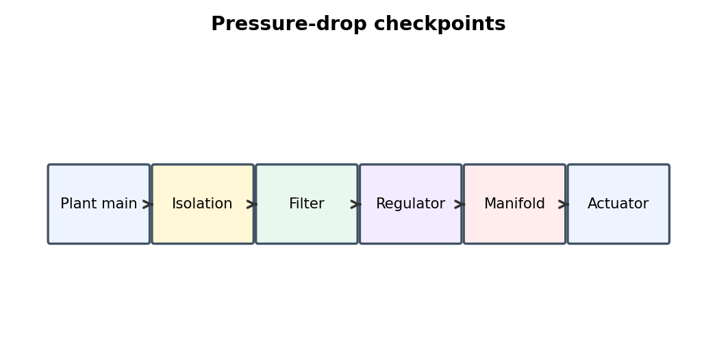
- Place the test point on each side of the suspected component.
- Run the exact failing condition.
- Compare values and move the test point based on the result.
Common mistakes
Testing only at idle. • Using an inaccurate or badly ranged gauge. • Creating a new restriction with test fittings.
FIELD RULE: Measure where the physics is happening, not where the nearest gauge happens to be.
Static vs. Dynamic Pressure
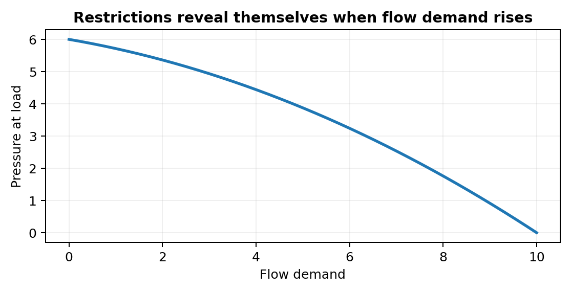
The most important pneumatic restrictions are often invisible until the actuator actually consumes air. Good pneumatic troubleshooting depends on measurements taken at the correct location and during the failing condition, with rated test equipment and controlled stored energy.
What to check
- Use a suitable pressure/flow range.
- Install test equipment only after safe depressurization where required.
- Measure locally and dynamically.
- Record results before changing settings.
Diagnostic sequence
- Define the question the measurement must answer.
- Place the test point on each side of the suspected component.
- Run the exact failing condition.
- Compare values and move the test point based on the result.
Common mistakes
Testing only at idle. • Using an inaccurate or badly ranged gauge. • Creating a new restriction with test fittings.
FIELD RULE: Measure where the physics is happening, not where the nearest gauge happens to be.
Flow Measurement
Flow meters quantify whether enough air is available for high-speed motion, air motors, and leak audits. Good pneumatic troubleshooting depends on measurements taken at the correct location and during the failing condition, with rated test equipment and controlled stored energy.
What to check
- Use a suitable pressure/flow range.
- Install test equipment only after safe depressurization where required.
- Measure locally and dynamically.
- Record results before changing settings.
Diagnostic sequence
- Define the question the measurement must answer.
- Place the test point on each side of the suspected component.
- Run the exact failing condition.
- Compare values and move the test point based on the result.
Common mistakes
Testing only at idle. • Using an inaccurate or badly ranged gauge. • Creating a new restriction with test fittings.
FIELD RULE: Measure where the physics is happening, not where the nearest gauge happens to be.
Pressure-Decay Testing
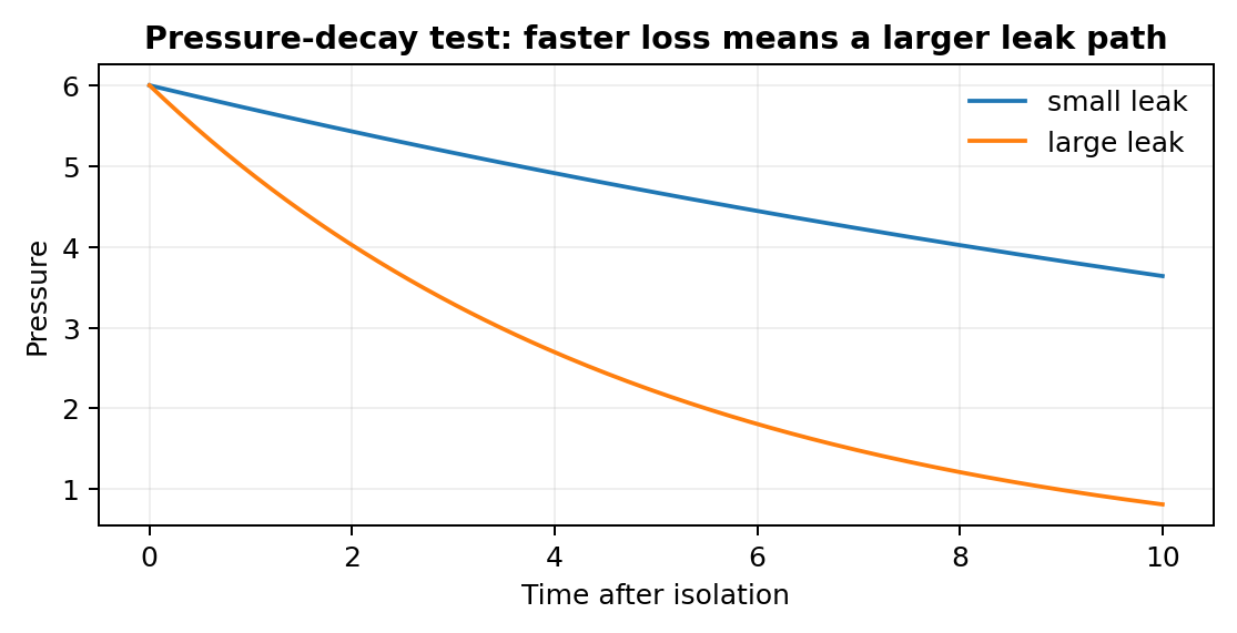
Pressure decay compares the total leak rate of an isolated volume over time. Good pneumatic troubleshooting depends on measurements taken at the correct location and during the failing condition, with rated test equipment and controlled stored energy.
What to check
- Use a suitable pressure/flow range.
- Install test equipment only after safe depressurization where required.
- Measure locally and dynamically.
- Record results before changing settings.
Diagnostic sequence
- Define the question the measurement must answer.
- Place the test point on each side of the suspected component.
- Run the exact failing condition.
- Compare values and move the test point based on the result.
Common mistakes
Testing only at idle. • Using an inaccurate or badly ranged gauge. • Creating a new restriction with test fittings.
FIELD RULE: Measure where the physics is happening, not where the nearest gauge happens to be.
Ultrasonic Leak Detection
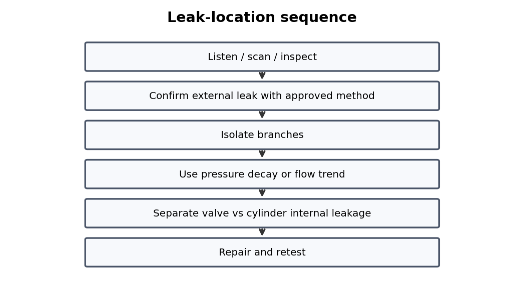
Ultrasound is useful in noisy plants but suspected signals still need physical verification. Good pneumatic troubleshooting depends on measurements taken at the correct location and during the failing condition, with rated test equipment and controlled stored energy.
What to check
- Use a suitable pressure/flow range.
- Install test equipment only after safe depressurization where required.
- Measure locally and dynamically.
- Record results before changing settings.
Diagnostic sequence
- Define the question the measurement must answer.
- Place the test point on each side of the suspected component.
- Run the exact failing condition.
- Compare values and move the test point based on the result.
Common mistakes
Testing only at idle. • Using an inaccurate or badly ranged gauge. • Creating a new restriction with test fittings.
FIELD RULE: Measure where the physics is happening, not where the nearest gauge happens to be.
Leak-Detection Solution
Bubble solution is excellent for external joints but cannot reveal internal valve or piston leakage. Good pneumatic troubleshooting depends on measurements taken at the correct location and during the failing condition, with rated test equipment and controlled stored energy.
What to check
- Use a suitable pressure/flow range.
- Install test equipment only after safe depressurization where required.
- Measure locally and dynamically.
- Record results before changing settings.
Diagnostic sequence
- Define the question the measurement must answer.
- Place the test point on each side of the suspected component.
- Run the exact failing condition.
- Compare values and move the test point based on the result.
Common mistakes
Testing only at idle. • Using an inaccurate or badly ranged gauge. • Creating a new restriction with test fittings.
FIELD RULE: Measure where the physics is happening, not where the nearest gauge happens to be.
Temporary Test Tees
A local test tee can reveal pressure collapse that a remote panel gauge completely misses. Good pneumatic troubleshooting depends on measurements taken at the correct location and during the failing condition, with rated test equipment and controlled stored energy.
What to check
- Use a suitable pressure/flow range.
- Install test equipment only after safe depressurization where required.
- Measure locally and dynamically.
- Record results before changing settings.
Diagnostic sequence
- Define the question the measurement must answer.
- Place the test point on each side of the suspected component.
- Run the exact failing condition.
- Compare values and move the test point based on the result.
Common mistakes
Testing only at idle. • Using an inaccurate or badly ranged gauge. • Creating a new restriction with test fittings.
FIELD RULE: Measure where the physics is happening, not where the nearest gauge happens to be.
Good vs. Bad Station Comparison
Repeated machine stations provide a built-in reference for pressure, timing, coil voltage, and exhaust behavior. Good pneumatic troubleshooting depends on measurements taken at the correct location and during the failing condition, with rated test equipment and controlled stored energy.
What to check
- Use a suitable pressure/flow range.
- Install test equipment only after safe depressurization where required.
- Measure locally and dynamically.
- Record results before changing settings.
Diagnostic sequence
- Define the question the measurement must answer.
- Place the test point on each side of the suspected component.
- Run the exact failing condition.
- Compare values and move the test point based on the result.
Common mistakes
Testing only at idle. • Using an inaccurate or badly ranged gauge. • Creating a new restriction with test fittings.
FIELD RULE: Measure where the physics is happening, not where the nearest gauge happens to be.
Isolation Testing
Dividing the circuit can separate valve leakage, cylinder leakage, plant leakage, and downstream restrictions. Good pneumatic troubleshooting depends on measurements taken at the correct location and during the failing condition, with rated test equipment and controlled stored energy.
What to check
- Use a suitable pressure/flow range.
- Install test equipment only after safe depressurization where required.
- Measure locally and dynamically.
- Record results before changing settings.
Diagnostic sequence
- Define the question the measurement must answer.
- Place the test point on each side of the suspected component.
- Run the exact failing condition.
- Compare values and move the test point based on the result.
Common mistakes
Testing only at idle. • Using an inaccurate or badly ranged gauge. • Creating a new restriction with test fittings.
FIELD RULE: Measure where the physics is happening, not where the nearest gauge happens to be.
Baseline Data
Normal pressure, cycle time, flow-control settings, and air consumption make future breakdown diagnosis much faster. Preventive pneumatic maintenance works best when it preserves known-good settings, removes leaks and contamination, and records baseline pressures and cycle times.
What to check
- Inspect for leaks, damaged tubing, loose mounts, and contamination.
- Check dynamic pressure and critical cycle times.
- Preserve documented flow-control and regulator settings.
- Record recurring failure locations and component changes.
Diagnostic sequence
- Inspect with machine in a controlled state.
- Measure before adjusting.
- Repair defects using correct rated parts.
- Recommission slowly and verify safety functions.
- Update maintenance records.
Common mistakes
Adjusting every valve during PM. • Replacing by appearance instead of specification. • Recording only “part replaced.”
FIELD RULE: Preventive maintenance should create better baseline data, not new unknown settings.
Continue the series
- Previous chapter: Electro-Pneumatic Control
- Next chapter: Pneumatic Symptom-Based Troubleshooting
- Browse all Pneumatic Troubleshooting chapters
Adapted from Pneumatic Troubleshooting for Maintenance Technicians, by Dovydas Kersys. © 2026 Dovydas Kersys. Featured cover image is an AI-generated editorial illustration.