If you work with PLC inputs, proximity sensors, photoelectric sensors, or industrial control panels, you will eventually meet the question:
Is this sensor PNP or NPN?
And yes, it matters.
A sensor can be perfectly good, the PLC input module can be perfectly good, the wiring can look almost right, and still nothing works because the sensor output type does not match the PLC input wiring.
This is one of the most common beginner mistakes in automation.
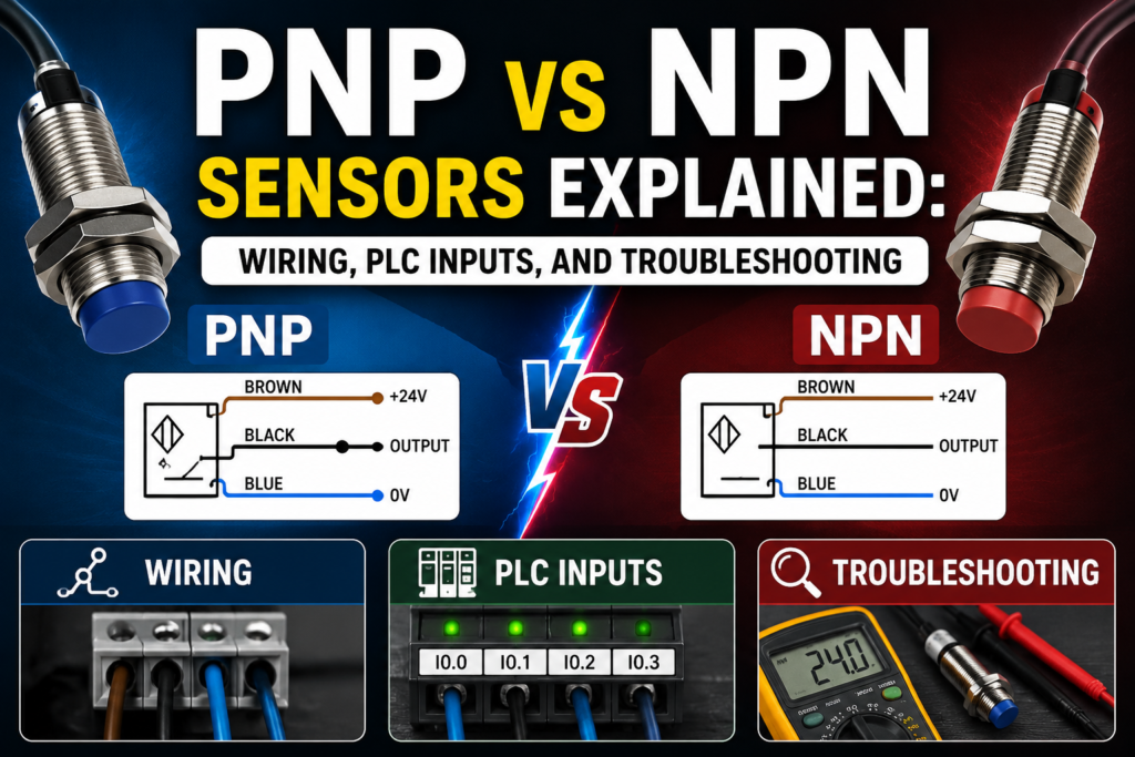
PNP and NPN sensors are both used to send digital ON/OFF signals to PLCs, counters, relays, and control systems. They can perform the same detection job, but they switch the signal in different ways.
In simple terms:
A PNP sensor switches positive voltage to the PLC input.
An NPN sensor switches the PLC input to 0 V.
That one sentence explains most of it.
But to wire and troubleshoot them correctly, we need to go a little deeper.
What Are PNP and NPN Sensors?
PNP and NPN sensors are three-wire DC sensors with transistor outputs.
They are commonly used in industrial automation for detecting objects, positions, levels, machine parts, cylinders, products, and many other conditions.
You will find PNP and NPN outputs in sensors such as:
- Inductive proximity sensors
- Capacitive sensors
- Photoelectric sensors
- Magnetic cylinder sensors
- Hall sensors
- Ultrasonic sensors
- Some pressure switches
- Some level sensors
- Some encoder or pulse devices
These sensors usually have three wires:
| Wire Color | Common Function |
|---|---|
| Brown | +24 V DC |
| Blue | 0 V DC |
| Black | Output signal |
The wire colors are common in many industrial sensors, but always check the sensor datasheet. Some devices may be different.
The sensor needs power to operate. Brown and blue provide the supply voltage. The black wire is the switching output that sends a signal to the PLC input.
The difference between PNP and NPN is what happens on that black output wire when the sensor turns ON.
What Is a PNP Sensor?
A PNP sensor is a sourcing sensor.
When the sensor is active, it connects the output wire to positive voltage.
For a typical 24 V DC system:
- Sensor inactive: output is OFF
- Sensor active: output sends +24 V DC to the PLC input
So a PNP sensor “sources” current to the input.
That is why PNP outputs are often called sourcing outputs.
In practical PLC wiring, the black output wire of a PNP sensor connects to the PLC input terminal. When the sensor detects the target, the black wire becomes positive, usually close to +24 V DC. The PLC input sees voltage and turns ON.
Simple.
The sensor gives the PLC input a positive signal.
PNP Sensor Wiring
A typical PNP sensor wiring looks like this:
| Sensor Wire | Connection |
| Brown | +24 V DC |
| Blue | 0 V DC |
| Black | PLC digital input |
The PLC input common is usually connected to 0 V, depending on the input module design.
When the sensor is active, current flows from the sensor output into the PLC input and then back to 0 V through the input common circuit.
Basic idea:
+24 V → sensor output → PLC input → 0 V
That is PNP wiring.
In many European industrial control panels, PNP sensors are very common because the PLC input receives a positive signal when the sensor is active.
This feels natural for many technicians:
24 V present = input ON.
No 24 V = input OFF.
What Is an NPN Sensor?
An NPN sensor is a sinking sensor.
When the sensor is active, it connects the output wire to 0 V.
For a typical 24 V DC system:
- Sensor inactive: output is OFF
- Sensor active: output switches toward 0 V
So an NPN sensor “sinks” current from the input.
That is why NPN outputs are often called sinking outputs.
With NPN wiring, the PLC input must normally be supplied from the positive side through the input circuit, and the sensor completes the path to 0 V when active.
In simple words:
The PLC input is pulled down to 0 V by the sensor.
That is the opposite switching style compared with PNP.
NPN Sensor Wiring
A typical NPN sensor wiring looks like this:
| Sensor Wire | Connection |
| Brown | +24 V DC |
| Blue | 0 V DC |
| Black | PLC digital input |
The sensor wires look the same as PNP at first. That is what makes this confusing.
The difference is in the PLC input common and current flow.
With an NPN sensor, the PLC input common is often connected to +24 V, depending on the PLC module design.
When the sensor is active, it pulls the input signal down to 0 V.
Basic idea:
+24 V → PLC input circuit → sensor output → 0 V
That is NPN wiring.
The sensor does not send +24 V to the input. It provides a path to 0 V.
PNP vs NPN: Main Difference
The main difference is how the sensor output switches current.
| Feature | PNP Sensor | NPN Sensor |
| Output type | Sourcing | Sinking |
| Active output | Sends +24 V | Connects to 0 V |
| Current direction | From sensor to PLC input | From PLC input through sensor to 0 V |
| PLC input common | Usually 0 V | Usually +24 V |
| Common logic | Positive signal = ON | Pull-down signal = ON |
| Common use | Very common in Europe | Common in some Asian/Japanese systems |
| Beginner-friendly logic | Easier for many technicians | More confusing if not expected |
A PNP sensor gives the input positive voltage.
An NPN sensor pulls the input to negative or 0 V.
That is the key difference.
Easy Way to Remember PNP and NPN
A simple way to remember:
PNP = Positive output
When active, a PNP sensor sends positive voltage to the PLC input.
NPN = Negative output
When active, an NPN sensor connects the PLC input to the negative side or 0 V.
This is not a perfect electronics definition, but it is a very useful field memory trick.
PNP pushes positive.
NPN pulls negative.
That is enough to avoid many wiring mistakes.
Why PNP and NPN Matter in PLC Wiring
PLC input modules are designed for a specific current flow.
Some input modules are sinking inputs. Some are sourcing inputs. Some can be wired either way, depending on the common terminal arrangement.
If the sensor output and PLC input type do not match, the input may not turn ON.
For example:
A PNP sensor needs the PLC input to accept positive voltage from the sensor.
An NPN sensor needs the PLC input circuit to provide current that the sensor can sink to 0 V.
If you wire an NPN sensor to a PLC input expecting a PNP signal, the sensor may switch correctly internally, but the PLC input will not see the correct voltage.
The result?
Sensor LED turns on.
PLC input LED stays off.
Technician gets annoyed.
Multimeter comes out.
Sourcing and Sinking Explained
The words sourcing and sinking describe the direction of current flow.
A sourcing device provides current to the load.
A sinking device receives current from the load and switches it to 0 V.
For sensors:
- PNP sensor = sourcing output
- NPN sensor = sinking output
For PLC inputs:
- Sinking input accepts current from a sourcing device
- Sourcing input provides current to a sinking device
This means PNP sensors are normally used with sinking PLC inputs.
NPN sensors are normally used with sourcing PLC inputs.
That sounds backwards at first, but it makes sense when you think about current flow.
The output and input must complement each other.
One side sources.
The other side sinks.
PNP Sensor With PLC Input Example
Let’s say you have a 24 V DC PNP inductive sensor connected to PLC input I0.0.
Connections:
- Brown wire to +24 V
- Blue wire to 0 V
- Black wire to I0.0
- PLC input common to 0 V
When no metal is detected:
- Sensor output is OFF
- Input I0.0 receives no positive voltage
- PLC input is OFF
When metal is detected:
- Sensor output switches to +24 V
- Input I0.0 receives voltage
- PLC input turns ON
This is the most common style many beginners learn first.
If you measure from black wire to blue wire:
- Inactive sensor: usually 0 V or floating, depending on sensor
- Active sensor: approximately +24 V DC
That is a good quick test.
NPN Sensor With PLC Input Example
Now let’s say you have a 24 V DC NPN sensor connected to PLC input I0.0.
Connections:
- Brown wire to +24 V
- Blue wire to 0 V
- Black wire to I0.0
- PLC input common to +24 V, depending on module
When no object is detected:
- Sensor output is OFF
- Input circuit is not pulled to 0 V
- PLC input is OFF
When object is detected:
- Sensor output connects input to 0 V
- Current flows from PLC input circuit through sensor to 0 V
- PLC input turns ON
If you measure the black wire to blue wire, the voltage behavior may look different than a PNP sensor. Depending on wiring and internal pull-up, the black wire may be high when inactive and low when active.
That is why knowing the input module wiring is important.
Normally Open and Normally Closed Sensor Outputs
PNP and NPN describe the electrical output type.
Normally open and normally closed describe the switching logic.
These are separate things.
A sensor can be:
- PNP normally open
- PNP normally closed
- NPN normally open
- NPN normally closed
- PNP/NPN configurable
- NO/NC configurable
For a normally open sensor:
- Output is inactive when no target is detected
- Output activates when target is detected
For a normally closed sensor:
- Output is active when no target is detected
- Output deactivates when target is detected
Do not confuse NO/NC with PNP/NPN.
PNP/NPN tells how the output switches electrically.
NO/NC tells when the output switches logically.
Different question.
Different answer.
PNP and NPN Sensor Wire Colors
Many three-wire DC sensors use standard wire colors.
| Wire Color | Function |
| Brown | +24 V DC |
| Blue | 0 V DC |
| Black | Output |
| White | Second output, teach input, or function wire on some sensors |
For a basic three-wire sensor, brown, blue, and black are the most common.
But never rely only on wire color.
Always check:
- Sensor label
- Datasheet
- Wiring diagram printed on sensor
- Part number
- Output type
- Supply voltage
- NO/NC logic
- Maximum output current
A wrong assumption with sensor wiring can damage the sensor or PLC input.
How to Identify If a Sensor Is PNP or NPN
There are several ways to identify the sensor type.
First, check the sensor body. Many sensors have the output type printed on the label.
You may see markings such as:
- PNP
- NPN
- PNP NO
- NPN NO
- PNP NC
- NPN NC
- Push-pull
- NO/NC
- 3-wire DC
Second, check the part number. Many manufacturers encode output type in the model number.
Third, check the datasheet. This is the safest method.
Fourth, measure the output behavior with a multimeter, if you know how to power the sensor safely.
For PNP, the output usually goes positive when active.
For NPN, the output usually switches to 0 V when active.
If you are unsure, do not guess. Check the documentation before connecting it to an expensive PLC input card.
How to Test a PNP Sensor With a Multimeter
To test a PNP sensor, power it correctly first.
Typical connections:
- Brown to +24 V DC
- Blue to 0 V DC
Set the multimeter to DC voltage.
Place the black meter probe on 0 V.
Place the red meter probe on the sensor output wire, usually black.
Now activate the sensor by bringing the target object into the detection area.
Expected readings for a PNP normally open sensor:
| Condition | Good Reading |
| No target | Around 0 V or no active voltage |
| Target detected | Around +24 V DC |
If the sensor LED turns on but the output does not change, the sensor output may be damaged, overloaded, or wired incorrectly.
If there is no supply voltage between brown and blue, the sensor cannot work.
Always check power first.
How to Test an NPN Sensor With a Multimeter
Testing an NPN sensor can be slightly less intuitive.
Power the sensor correctly:
- Brown to +24 V DC
- Blue to 0 V DC
The output switches to 0 V when active, but to see this clearly you may need a load or pull-up path, depending on the sensor and test setup.
In a real PLC circuit, measure the input terminal voltage according to the PLC common wiring.
For a basic check, you can measure between the output wire and +24 V.
Place the red meter probe on +24 V.
Place the black meter probe on the sensor output wire.
When the NPN output turns ON, it should create a voltage difference because the output is pulled toward 0 V.
Expected behavior for an NPN normally open sensor:
| Condition | Typical Behavior |
| No target | Output not sinking |
| Target detected | Output switches toward 0 V |
In the actual PLC panel, it is often easier to check whether the PLC input LED changes when the sensor activates. Then confirm with voltage measurements at the input terminal and common.
Good and Bad Readings
Here are common expected readings in a 24 V DC system.
For a PNP normally open sensor:
| Test Point | Sensor Inactive | Sensor Active | Meaning |
| Brown to blue | ~24 V DC | ~24 V DC | Sensor has supply |
| Black to blue | ~0 V | ~24 V DC | Output switches positive |
| PLC input LED | OFF | ON | PLC sees signal |
For a PNP sensor, bad signs include:
| Reading | Possible Problem |
| Brown to blue = 0 V | No sensor supply |
| Black never goes to 24 V | Sensor not detecting, faulty output, wrong type, overload |
| Black always 24 V | Sensor stuck ON, wrong NO/NC type, short to +24 V |
| PLC input LED off while black has 24 V | Wrong PLC common, bad input, wrong address, broken terminal |
For an NPN sensor, expected readings depend more on the PLC input module wiring, but common bad signs include:
| Symptom | Possible Problem |
| Sensor LED ON but PLC input OFF | Wrong PLC input type, wrong common wiring, broken output wire |
| Input always ON | Short to 0 V, wrong NO/NC type, wiring mistake |
| Input never ON | No sensor supply, wrong output type, no pull-up/input current path |
| Sensor output voltage does not change | Damaged sensor or wrong test method |
Common PNP/NPN Wiring Mistakes
PNP and NPN problems are very common in real maintenance work.
Typical mistakes include:
- Buying NPN sensor when the panel uses PNP inputs
- Buying PNP sensor when the PLC input expects NPN
- Wiring PLC input common to the wrong polarity
- Mixing PNP and NPN sensors on the same input group
- Assuming all three-wire sensors are PNP
- Confusing NO/NC with PNP/NPN
- Ignoring the sensor wiring diagram
- Using AC sensor on DC input
- Using two-wire sensor where three-wire sensor is expected
- Measuring output voltage with the wrong reference point
- Forgetting common 0 V between power supply and PLC input
- Replacing a sensor with a similar-looking but different output type
The most painful mistake is replacing a faulty PNP sensor with an NPN sensor because the connector fits.
The connector fitting does not mean the sensor is electrically compatible.
Can You Mix PNP and NPN Sensors?
Sometimes yes, but not always.
It depends on the PLC input module.
Some PLC input modules have separate common terminals per input group. This may allow one group to be wired for PNP sensors and another group for NPN sensors.
Other modules have a shared common for many inputs. In that case, mixing PNP and NPN sensors on the same common group may not be possible.
Some modern PLC input modules are flexible and can accept both sourcing and sinking wiring. Others are fixed.
Before mixing sensor types, check:
- PLC input module datasheet
- Input common grouping
- Wiring diagram
- Sensor output type
- Power supply arrangement
In practice, it is usually cleaner to standardize one sensor type in a panel or machine.
For many European-style 24 V DC systems, that usually means PNP.
PNP vs NPN in PLC Ladder Logic
From the PLC program side, PNP and NPN may look the same.
The PLC input is either ON or OFF.
For example, input I0.0 turns ON when the sensor detects a target.
The ladder logic does not always care whether the field sensor is PNP or NPN. It only sees the input state.
However, the physical wiring must be correct before the program can work.
This is important:
PNP/NPN is mostly a wiring and hardware issue.
NO/NC and program contact type are logic issues.
For example, if the sensor input turns ON when the part is detected, the PLC program can use a normally open contact instruction to check for part detected.
If the input turns OFF when the part is detected, the program logic may need to be inverted.
Always confirm the real input behavior online.
Do not program based only on what you think the sensor should do.
PNP vs NPN and Sensor Replacement
When replacing a sensor, match more than just the size.
You should check:
- Supply voltage
- Output type: PNP or NPN
- Output logic: NO or NC
- Connector type
- Sensing distance
- Sensor diameter
- Mounting style
- Shielded or unshielded type
- Output current rating
- Switching frequency
- Environmental rating
- Cable length
- Wiring diagram
A sensor may physically fit but behave differently.
For example, replacing a PNP NO sensor with a PNP NC sensor may make the PLC input work backwards.
Replacing a PNP sensor with an NPN sensor may make the input not work at all.
Always compare the full part number or datasheet.
Troubleshooting: Sensor LED ON but PLC Input OFF
This is a very common fault.
The sensor detects the object. The sensor LED turns ON. But the PLC input does not change.
Possible causes:
- Sensor output type does not match PLC input
- Missing PLC input common
- Broken black output wire
- Loose terminal
- Wrong PLC input address
- Input module common wired to wrong polarity
- Input module damaged
- Sensor output damaged
- Sensor output overloaded
- Wrong connector pinout
- PLC input group has no field power
What to check:
- Measure sensor supply voltage between brown and blue.
- Measure sensor output voltage when inactive and active.
- Measure voltage directly at the PLC input terminal.
- Check PLC input LED.
- Check PLC online input status.
- Confirm the input address in the program.
- Check PNP/NPN compatibility.
Do not replace the PLC first.
Most of the time, the problem is wiring, common voltage, sensor type, or wrong address.
Troubleshooting: PLC Input Always ON
If the PLC input stays ON all the time, possible causes include:
- Sensor output stuck ON
- Wrong NO/NC sensor type
- Output wire shorted to +24 V in PNP system
- Output wire shorted to 0 V in NPN system
- Wrong common wiring
- Leakage current from two-wire sensor
- PLC input forced ON in software
- Incorrect program interpretation
- Input module fault
Check with a multimeter at the input terminal.
Then disconnect the sensor output wire from the PLC input, if safe and allowed.
If the input turns OFF after removing the wire, the problem is likely in the sensor or field wiring.
If the input stays ON with the wire removed, check PLC forcing, module fault, or wiring backfeed.
Troubleshooting: PLC Input Never Turns ON
If the input never turns ON, possible causes include:
- No sensor supply voltage
- Sensor not detecting target
- Wrong sensing distance
- Wrong target material
- Wrong PNP/NPN type
- Broken output wire
- Bad connector
- Wrong PLC input common
- Blown input fuse or field supply
- Damaged PLC input
- Sensor output overloaded
- Wrong input address in program
Check the basics first.
Does the sensor have power?
Does the sensor LED change?
Does the output voltage change?
Does voltage reach the PLC terminal?
Does the PLC input LED turn ON?
Does the program use the correct input address?
Follow the signal step by step from the sensor to the PLC.
PNP and NPN With M12 Connectors
Many industrial sensors use M12 connectors.
A common 4-pin M12 DC sensor pinout is:
| Pin | Common Wire Color | Function |
| 1 | Brown | +24 V DC |
| 3 | Blue | 0 V DC |
| 4 | Black | Output 1 |
| 2 | White | Output 2 or additional function |
This is common, but not universal.
Always check the sensor pinout and cable pinout.
A wrong M12 cable or different pin assignment can cause the sensor to power up but not send the expected signal.
Also, some sensors have both NO and NC outputs on different pins. Others use the white wire for teach-in or configuration.
Do not assume.
Which Is Better: PNP or NPN?
Neither is universally better.
Both can work reliably when matched correctly with the PLC input module and wiring standard.
However, in many modern European industrial automation systems, PNP sensors are more common.
Reasons many technicians prefer PNP:
- Active signal is positive voltage
- Easier to understand during troubleshooting
- Common with 24 V DC PLC inputs
- Less confusing for electricians used to “voltage present = ON”
- Often preferred in European machinery
NPN sensors are still widely used in some regions, machine types, and older equipment.
The best choice is the one that matches your PLC input module, plant standard, and existing machine wiring.
Standardization matters more than personal preference.
Quick Selection Guide
Use this simple guide:
Choose PNP sensors when:
- Your PLC input common is wired to 0 V
- Your PLC expects positive voltage on the input
- Your machine standard uses sourcing sensors
- You want common European-style 24 V DC sensor wiring
Choose NPN sensors when:
- Your PLC input common is wired to +24 V
- Your PLC expects the sensor to pull the input to 0 V
- Existing machine wiring uses sinking sensors
- Your equipment standard requires NPN outputs
Before ordering sensors, always confirm the PLC input type.
That one check can save hours.
Practical Field Checklist
Before connecting a PNP or NPN sensor, check:
- Sensor supply voltage
- Sensor output type
- NO or NC output logic
- PLC input module type
- Input common wiring
- Sensor wire colors
- Connector pinout
- Load current rating
- Input address
- Machine electrical drawing
During troubleshooting, check:
- Sensor LED
- Brown-to-blue supply voltage
- Output voltage change
- Voltage at PLC input terminal
- PLC input LED
- PLC online input status
- Program logic
- Common terminals
- Loose wires or broken cables
This checklist solves most PNP/NPN problems.
Not all of them.
But most.
Final Thoughts
PNP and NPN sensors are both common in industrial automation, but they switch the PLC input signal in different ways.
A PNP sensor is a sourcing output. When active, it sends positive voltage, usually +24 V DC, to the PLC input.
An NPN sensor is a sinking output. When active, it switches the PLC input toward 0 V.
The sensor type must match the PLC input module wiring. If it does not, the sensor may detect correctly, but the PLC input may never turn ON.
The most important things to remember are:
PNP sends positive.
NPN pulls negative.
NO and NC are not the same as PNP and NPN.
PLC input common wiring matters.
Always check the datasheet before replacing a sensor.
Most PNP vs NPN problems are not complicated once you understand the current path. Follow the voltage, check the common, confirm the output type, and watch the PLC input status.
The sensor is only one part of the circuit.
The PLC input must be wired to understand it.