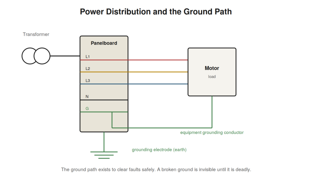
Before you can troubleshoot a fault in the distribution system, you need a working picture of how power gets from the source to the load. This chapter builds that picture at the level a troubleshooter needs — not the depth of a design engineer, but enough to know what should be where and why.
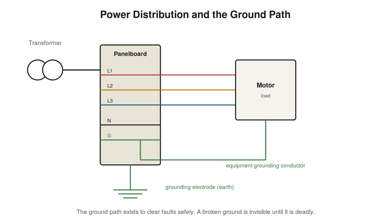
From transformer to load
Industrial power typically arrives through a transformer that steps the utility voltage down to a usable level and establishes the system’s grounding reference. From the transformer, power feeds a distribution panel or switchboard, which divides it among feeders protected by fuses or circuit breakers. Those feeders supply subpanels, motor control centers, and individual loads. At each stage there is protection sized to the conductors and equipment it serves. Understanding this hierarchy tells you, when a fault appears, how far upstream to look: a single dead machine points at its own circuit, while a whole area losing power points at a feeder or main upstream.
Three-phase power in brief
Most industrial power is three-phase, meaning three alternating voltages offset in time, which delivers power more efficiently and runs motors smoothly. For the troubleshooter, the key practical facts are that three-phase loads depend on all three phases being present and balanced, that the loss of one phase is a serious and common fault, and that phase rotation (the order in which the phases peak) determines motor direction. Measuring all three phase-to-phase and phase-to-ground voltages, and comparing them, is a foundational check that reveals a lost or unbalanced phase immediately.
Grounding and bonding: safety’s foundation
Grounding and bonding are among the most misunderstood and most important parts of an electrical system, and faults in them are both dangerous and hard to see. Bonding ties all the metal equipment enclosures together and to the system ground, so that everything a person might touch sits at the same potential. Grounding connects that bonded system to earth. Together they do two critical jobs: they provide a low-resistance path for fault current so that protective devices trip quickly when a live conductor contacts a metal enclosure, and they keep exposed metal from becoming energized to a dangerous voltage. A broken or high-resistance ground path is invisible during normal operation and lethal during a fault, because the protection that should clear the fault cannot operate and the enclosure the fault energizes stays live. This is why grounding integrity is a safety issue of the first order, not a formality.
NEC AND IEC TERMSNorth American (NEC) practice speaks of the equipment grounding conductor and grounding electrode; international (IEC) practice speaks of protective earth (PE) and earthing, and classifies systems as TN, TT, or IT by how they handle the earth connection. The names differ but the purpose is the same: a safe path for fault current and a stable reference that keeps touchable metal safe. |
A case file: the whole area goes dark
An entire section of a plant loses power at once — several machines, lights, and outlets all dead together. The scope of the outage is the key clue: when many loads fail simultaneously, the fault lies not in any one of them but in something they share upstream. Rather than investigating each dead machine, the technician goes to the panel or feeder that supplies the whole area and finds a tripped main breaker. The question then becomes why it tripped, and reading the situation — did it trip on overload or fault, what was running when it went — guides the investigation upstream to the actual cause, which proves to be a faulted feeder cable. The lesson is to let the scope of an outage direct you: a single dead machine points at its own circuit, while a whole area failing together points at the shared feeder, panel, or main that supplies them all, and going straight to that shared point is far faster than examining each affected load.
The grounding system you cannot see
Grounding and bonding faults are uniquely insidious because the system works normally right up until a fault occurs, at which point the missing ground path turns a manageable fault into a dangerous one. A loose grounding connection, a bond that was never made, a grounding conductor that corroded through — none of these announce themselves during normal operation, because ground normally carries no current. Their danger appears only when a ground fault occurs and the current cannot flow freely to trip the protection, leaving an enclosure energized. This is why verifying the integrity of the grounding and bonding system is a fundamental check that is too often skipped: it protects against a hazard that is invisible until the worst moment. When troubleshooting, and especially when exposed metal reads an unexpected voltage or a system behaves erratically in ways that hint at grounding, confirming the continuity of the ground path is both a diagnostic step and a safety measure.
Scoping a fault by what is affected
The scope of what has failed is one of the most useful early observations in distribution troubleshooting, because it points directly at how far upstream the fault lies. A single dead load points at that load’s own circuit — its breaker, its wiring, itself. A group of loads dead together points at what they share: a common feeder, a subpanel, a section of distribution. An entire area dark points at a main or a major feeder upstream. Reading this scope before investigating any individual load directs you to the right level of the distribution hierarchy, saving the wasted effort of examining one dead machine when a whole panel is out. The principle is that simultaneous failures share a cause, and that cause lies at the point the failed items have in common, so identifying what the affected loads share — and going straight to that shared point — is far faster than treating each failure separately. The distribution hierarchy, understood as a tree from source to loads, is the map that turns the scope of an outage into a location to investigate.
The neutral and its quiet importance
In systems with a neutral conductor, the neutral carries the unbalanced return current and establishes a reference, and neutral problems produce some of the more confusing faults a troubleshooter meets. A loose or high-resistance neutral connection can cause voltages to shift as loads change, so that some equipment sees too high a voltage while other equipment sees too low, with the pattern varying as the load balance shifts — a baffling symptom until the neutral is suspected. An overloaded neutral, sometimes worsened by harmonic currents from electronic loads that accumulate in the neutral, can overheat. Because the neutral normally sits near ground potential and carries only unbalanced current, its problems are easy to overlook, yet a compromised neutral can damage equipment and produce erratic, load-dependent voltage problems that resist explanation until the neutral connection is checked. When voltages shift oddly with changing load, or when a neutral runs hot, the neutral connection and its integrity deserve direct attention.
Three-phase fundamentals a troubleshooter must own
Three-phase power underlies most industrial systems, and a handful of practical facts about it are essential troubleshooting equipment, quite apart from any deeper theory. First, three-phase loads depend on all three phases being present and reasonably balanced, so the loss of one phase is a serious and common fault with characteristic symptoms. Second, the three phase-to-phase voltages should be roughly equal, and comparing them immediately reveals a missing or low phase or an unbalance. Third, phase rotation — the order in which the three phases reach their peaks — determines the direction a three-phase motor turns, so a motor running backward after work has been done often has two phases swapped. Fourth, unbalance short of a full phase loss, though it looks minor on a voltmeter, stresses three-phase motors disproportionately and is worth catching. These facts turn the routine check of measuring and comparing all three phases into a powerful diagnostic that reveals lost phases, unbalance, and rotation problems at a glance, and they are the practical core of what a troubleshooter needs to own about three-phase power to work confidently with the motors and loads that depend on it.
Grounding and bonding as the system’s safety foundation
It is worth consolidating why grounding and bonding, though they carry no current in normal operation and are easily treated as a formality, are in fact the safety foundation of the entire electrical system. Bonding ties all the touchable metal — enclosures, frames, conduit — together so that everything a person might contact sits at the same potential, preventing a dangerous voltage difference between two things someone could touch at once. Grounding connects that bonded system to earth, establishing a reference and, crucially, providing a low-resistance path for fault current. Together they accomplish two safety-critical jobs: they give fault current a path that lets protective devices operate quickly to clear a fault, and they keep exposed metal from rising to a dangerous voltage when a fault energizes it. The insidious quality of grounding and bonding faults — that they show no symptom until a fault occurs, at which point the missing path turns a manageable fault deadly — is exactly why their integrity must be verified deliberately rather than assumed from normal operation. Whether described in NEC terms of equipment grounding conductors and grounding electrodes or IEC terms of protective earth and TN, TT, and IT systems, the purpose is identical and fundamental: a safe path for fault current and a stable reference that keeps touchable metal safe, making grounding and bonding not a formality but the silent foundation on which the safety of the whole system rests.
A case file: the load-dependent voltage problem
Equipment in one area behaves strangely, with some devices seeming to get too much voltage and others too little, and the pattern shifts confusingly as different loads switch on and off through the day. No single faulted component can be found, because no single component is at fault. The shifting, load-dependent nature of the problem points at the neutral: a loose, high-resistance neutral connection cannot properly carry the unbalanced return current and hold the neutral point at its correct reference, so as the balance of loads changes, the neutral point shifts, driving some phases high and others low in a pattern that varies with the load balance. The individual devices are healthy; the fault is the compromised neutral connection upstream, producing voltage problems across everything downstream that change as the loads change. Finding and remaking the neutral connection restores stable correct voltages. The case illustrates a fault that resists explanation until the neutral is suspected: when voltages shift oddly and in a load-dependent way, with some equipment high and some low and the pattern changing as loads switch, a compromised neutral connection is a prime suspect, because the neutral’s job of carrying unbalanced current and holding the reference is exactly what fails in a way that produces shifting, load-dependent voltage across everything it serves. The neutral, carrying no current in a perfectly balanced system and easy to overlook, can produce some of the most baffling distribution faults when its connection degrades.
Transformers and what they establish
The transformer that typically brings power into an industrial installation does more than change the voltage; it establishes characteristics of the system downstream that matter to troubleshooting. It sets the voltage level the facility works at, stepping the incoming supply down to a usable level. It often establishes the system’s grounding reference, determining how the system relates to earth — a relationship that NEC practice and IEC practice describe differently but that fundamentally shapes how ground faults behave. And it defines, through its size and impedance, how much fault current is available downstream, which in turn determines the arc-flash hazard and the sizing of protective devices. For the troubleshooter, the transformer is worth understanding as the source that establishes these downstream conditions: the voltage to expect, the grounding arrangement that governs ground-fault behavior, and the available fault energy that sets the hazard level. A transformer problem — though transformers are robust and fail less often than the equipment they feed — affects everything downstream, and a fault that takes out a whole facility’s supply may lie at the transformer or its connections. More commonly, the transformer simply frames the context within which downstream troubleshooting happens, defining what normal looks like for the voltages, the grounding, and the fault levels that the rest of the system operates within, which is why a troubleshooter benefits from knowing what transformer feeds their area and what it establishes.