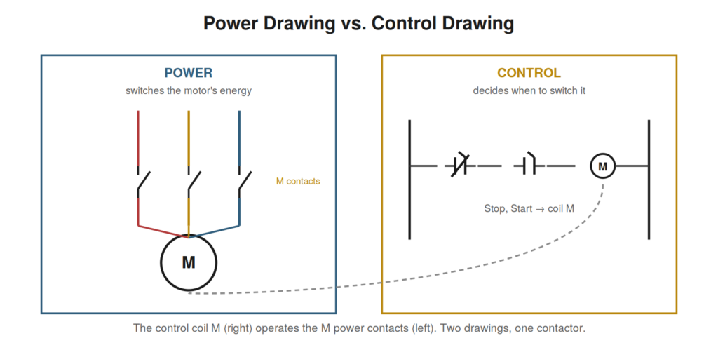
A complete electrical drawing set separates two related but distinct concerns: the power that does the work, and the control that decides when. Understanding how power and control drawings relate — and how they connect through shared devices — is key to navigating a full drawing set and to troubleshooting, because the same fault symptom can live in either world.
Two drawings, two jobs
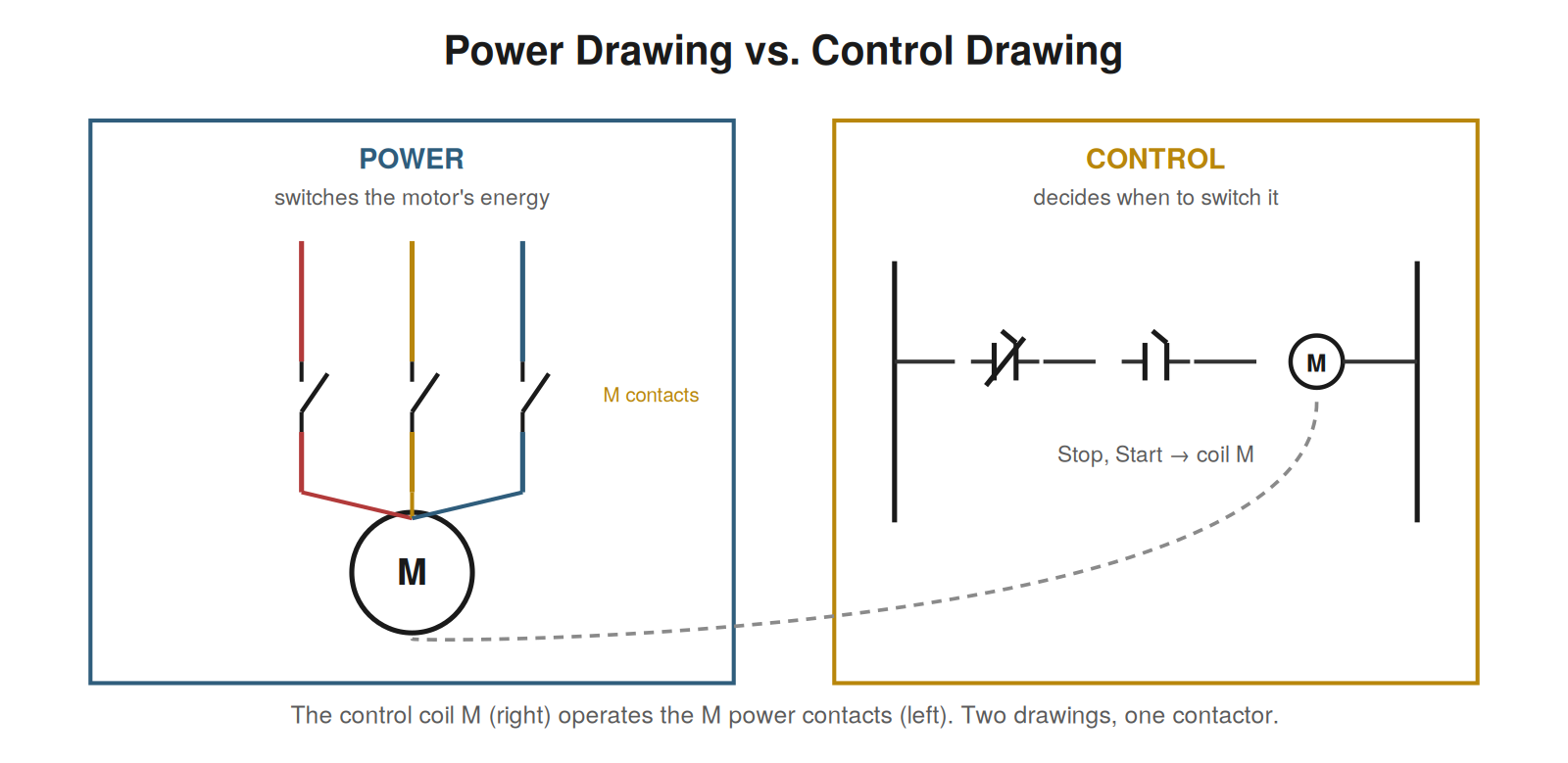
The power drawing shows how energy reaches the load — the path from the supply through disconnects, protection, and switching devices to the motor or other load, often carrying substantial current and, for motors, three phases. The control drawing shows the logic that decides when the load operates — the buttons, conditions, and relay logic that ultimately command the switching device. These are drawn separately because they are different in nature: the power circuit is about carrying and switching energy, while the control circuit is about logic and decisions, usually at a lower voltage. Reading a system means reading both, and understanding that the control drawing’s decisions are carried out by the power drawing’s switching devices.
The contactor: where they meet
The device that links the power and control drawings is typically the contactor. Its coil appears on the control drawing, driven by the control logic, and its main contacts appear on the power drawing, switching the motor’s power. They are the same physical device, connected on the drawings by their shared label: energizing the coil (control side) closes the main contacts (power side), delivering power to the motor. Reading across the two drawings means following this link — recognizing that the coil you see energized on the control drawing operates the main contacts you see on the power drawing, because they bear the same contactor label. This shared-label link between control and power is the key relationship for reading a full motor control scheme, and it is what lets you follow a start command from the control logic all the way to the motor receiving power.
Which drawing holds the fault
The power-versus-control distinction is central to troubleshooting, because a dead motor could have its fault in either world, and they are found in different places. If the control logic is not energizing the contactor coil, the fault is on the control side — a condition not met, a control wire, the coil. If the coil is energizing and the contactor operating but the motor still has no power, the fault is on the power side — the main contacts, the motor power wiring, the motor. Determining which world the fault lives in, by checking whether the contactor coil is energizing and the contactor operating, splits the search in half and directs you to the right drawing. Reading both drawings and understanding their link is what makes this split possible, turning a dead motor into a targeted search on either the control drawing or the power drawing rather than a hunt through both.
A worked example: splitting a dead-motor fault
The power-versus-control split is best understood through a worked fault. A motor will not run. Reading the drawings, you know the control circuit energizes contactor coil M, and M’s main contacts (on the power drawing) deliver power to the motor. The diagnostic question that splits the fault in half: is coil M energizing? You check — perhaps by observing the contactor, which visibly and audibly pulls in when its coil energizes, or by measuring at the coil. If M is not energizing, the fault is on the control side: read the control rung and check its conditions (Stop, Start, permissives, overload). If M is energizing and the contactor is pulling in but the motor still has no power, the fault is on the power side: check the main contacts, the motor wiring, the motor itself. This single question — is the coil energizing? — directs you to the correct drawing and halves the search. Reading both drawings and understanding their link through the shared contactor label is what makes this powerful split possible.
Why the split saves the most time
Of all the reading-based techniques, the power-versus-control split may save the most time per unit of effort, because a single observation eliminates half the possible fault locations. A dead motor has many possible causes spread across both the control and power circuits, and without the split you might check them in any order, possibly exhausting the control side before discovering the fault was on the power side or vice versa. The split — determining whether the contactor coil is energizing — instantly tells you which half to search, so you never waste time on the wrong half. This is the power of a well-chosen diagnostic question: it partitions the fault space efficiently. Reading the two drawings and understanding their link through the contactor is what lets you pose the question and interpret the answer, and it is why understanding the power-versus-control relationship is so valuable. One observation, made possible by reading, halves the work — and often the observation is easy, since a contactor pulling in is visible and audible, requiring no measurement at all to answer the question that splits the fault.
Following a command from control to power
A clarifying exercise is to follow a single command — a start — all the way from the control drawing to the motor receiving power, crossing from control to power via the contactor. On the control drawing: the operator presses Start, completing the rung that energizes the contactor coil M. The coil, energized, operates the contactor. On the power drawing: the contactor’s main contacts, operated by that same coil, close, connecting the motor to the three-phase supply. The motor receives power and runs. Following this command across the two drawings — Start closes the control rung, energizing coil M, whose main contacts on the power drawing close to power the motor — traces the complete path from operator action to motor rotation, crossing the control-to-power boundary at the contactor. Reading this path is understanding how the two drawings work together: control decides and commands, power carries out the command, and the contactor is where the command crosses from the logic that decided it to the power circuit that executes it. This following of a command from control to power is the integrated reading of a full motor control scheme.
Control voltage and why it differs from power
An aspect of the power-control division worth reading carefully is the control voltage, which usually differs from the power voltage, and understanding why clarifies the two circuits’ relationship. Power circuits often run at higher voltages suited to delivering energy to motors and heavy loads, while control circuits frequently run at a lower voltage — derived through a control transformer — suited to the buttons, relays, and logic, and safer for operators to interact with. Reading the drawing, the control transformer is where the control voltage is derived from the power supply, marking the boundary where the control circuit branches off at its own voltage. Understanding this tells you that the control circuit operates at a different, usually lower voltage than the power circuit, which matters when measuring (you expect different voltages in each) and for understanding the safety rationale (lower control voltage is safer for the operator interface). Reading the control transformer and recognizing the control voltage it provides is part of reading how power and control relate: they operate at different voltages, connected through the control transformer, with the control circuit at the lower voltage appropriate to logic and human interaction, and the power circuit at the higher voltage appropriate to delivering energy to the load.
Case: coil energized, motor dead
The power-versus-control split resolves this classic case cleanly. A motor would not run, and applying the split, the technician checked whether the contactor coil was energizing — and it was, the contactor visibly and audibly pulling in. This immediately located the fault on the power side: the control had done its job (coil energized, contactor operated), but the motor still had no power, so the fault lay in the power circuit after the contactor. Reading the power drawing, the technician checked the contactor’s main contacts, the motor wiring, and the motor — finding the fault in the power path (a main contact not making, or a power connection open). Had the coil not energized, the fault would have been on the control side, and the technician would have read the control rung instead. This case shows the split in action: the single observation that the coil was energizing directed the technician to the power side, halving the search and leading to the fault in the power path. Reading both drawings and understanding the contactor link is what made the split possible — knowing that an energized coil with a dead motor means a power-side fault, because the control has succeeded and only the power circuit remains. The split turned a dead-motor fault into a focused search of just the power side, guided by one easy observation of the contactor.
Integrating the two into one understanding
The goal in reading power and control drawings is to integrate them into a single understanding of the machine, seeing the two drawings as two views of one system rather than separate things. The control drawing shows the decision-making; the power drawing shows the energy delivery; and the machine is both together, linked through devices like the contactor that appear in both. Reading them integrated means understanding a start command as flowing from the control logic’s decision, through the contactor, to the power circuit’s delivery of energy to the motor — one continuous story across two drawings. This integrated reading is more powerful than reading either drawing alone, because it captures how the machine actually works: control deciding, power executing, linked at the contactor. Developing this integration — habitually connecting the control and power views into one understanding — is part of maturing as a reader, moving from reading individual drawings to understanding the whole machine they jointly describe. The two drawings are complementary views of one system, and reading them as such, integrated into a single understanding of how the machine decides and acts, is the sophisticated reading that fully comprehends a machine’s electrical operation, from the control logic’s decisions through to the power circuit’s delivery of energy, as one connected whole rather than two separate drawings.