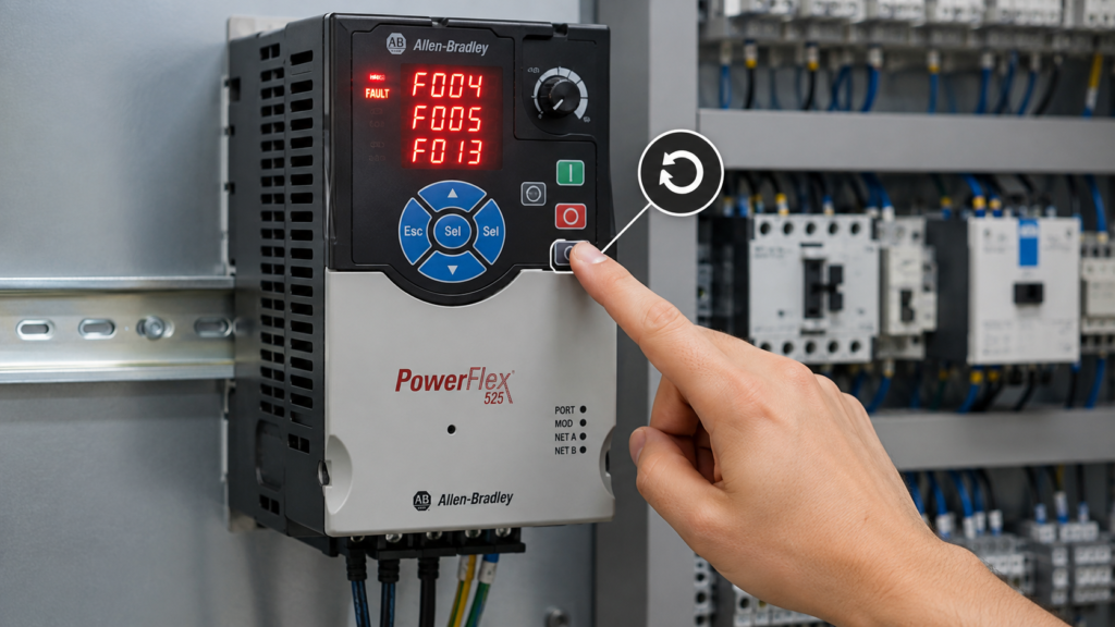
A PowerFlex 525 stops and flashes F004, F005 or F013.
Pressing the Stop button may clear it. Sometimes the motor even starts again.
Problem solved? Not quite.
A reset only removes the active fault. It does not repair a weak incoming supply, shorten a damaged motor cable, reduce regenerative energy or restore failing motor insulation. When the underlying condition remains, the drive usually trips again—often at the worst possible moment.
This guide explains what these three common PowerFlex 525 faults mean, what to check and how to reset the drive properly.
Safety warning: PowerFlex drives contain hazardous voltage, and the DC bus can remain charged after incoming power is removed. Follow lockout/tagout procedures and verify that the bus has discharged before touching drive, motor or cable connections. A fault reset may allow the motor to restart if a run command remains active.
Quick Fault-Code Summary
| Fault | Meaning | Most likely area |
|---|---|---|
| F004 | UnderVoltage | Incoming supply, fuses, contactor or voltage drop |
| F005 | OverVoltage | High line voltage or motor regeneration |
| F013 | Ground Fault | Motor cable, motor insulation or drive output stage |
Rockwell defines F004 as the DC bus falling below its minimum value, F005 as the DC bus exceeding its maximum value and F013 as current finding a path to earth ground from one or more output terminals.
F004 UnderVoltage
The drive displays F004 UnderVoltage when its internal DC-bus voltage falls below the minimum operating level.
The VFD first converts the incoming AC supply into DC. If the incoming voltage disappears or drops far enough, the DC bus cannot remain at the level required to operate the inverter section.
Rockwell’s recommended action is to monitor the incoming AC line for low voltage or a line-power interruption.
Common causes of F004
Typical causes include:
- Low incoming AC voltage
- A short power interruption or severe voltage dip
- A loose input terminal
- A damaged input contactor
- A blown or high-resistance fuse
- One missing input phase
- An undersized supply transformer
- Excessive voltage drop in long supply cables
- Several large loads starting at the same time
- The wrong voltage-class drive for the available supply
Do not limit the test to measuring the supply while the machine is stopped. A weak connection can show the expected voltage without load and then collapse when the motor accelerates.
How to troubleshoot F004
Start by recording when the fault occurs.
Does it happen:
- Immediately after the run command?
- During motor acceleration?
- When another large motor starts?
- Randomly while the machine is running?
- During a plant-wide voltage disturbance?
That timing gives you somewhere useful to begin.
1. Measure all incoming phases
Measure line-to-line voltage at the drive input terminals:
R/L1 to S/L2
S/L2 to T/L3
R/L1 to T/L3
Compare the readings with the drive’s rated input voltage.
Whenever possible and permitted, monitor the voltage while the drive accelerates the motor. A static reading may not reveal a brief voltage sag.
2. Inspect the complete input path
Check:
- Main disconnect
- Circuit breaker
- Input fuses
- Input contactor
- Line reactor, if installed
- Supply terminals
- Cable connections
- Transformer terminals
Look for heat discoloration, loose conductors, damaged fuse holders and burned contactor poles.
3. Check the DC-bus reading
Parameter b005 [DC Bus Voltage] displays the drive’s filtered DC-bus voltage. The PowerFlex 525 also stores the bus voltage present when recent faults occurred in parameters F651 through F660.
This is particularly useful for intermittent faults. You may not be standing beside the panel when the voltage dip happens, but the stored value can provide evidence of what the drive saw.
4. Compare the fault with other equipment
When several drives or contactors drop out at the same time, the problem is probably not inside one PowerFlex 525.
Investigate the common supply, transformer, distribution panel or upstream protection.
F005 OverVoltage
The drive displays F005 OverVoltage when its internal DC-bus voltage rises above the maximum permitted value.
High incoming line voltage can cause this, but motor regeneration is often the more interesting culprit.
When a fast-moving or high-inertia load is forced to decelerate quickly, the motor can behave like a generator. Energy flows back into the drive and raises its DC-bus voltage. When the drive cannot absorb or dissipate that energy quickly enough, it trips on F005.
Rockwell recommends checking for high line voltage and transients. It also identifies motor regeneration as a possible cause and recommends extending the deceleration time or installing a suitable dynamic-braking option.
Common causes of F005
Typical causes include:
- Incoming voltage that is too high
- Supply-voltage transients
- Deceleration time set too short
- A high-inertia load
- An overhauling load driving the motor
- A braking resistor that is missing, disconnected or incorrectly selected
- Repeated rapid stopping
- Mechanical equipment pushing energy back into the motor
- Unsuitable stopping or bus-regulator settings
Common examples are centrifuges, large fans, heavy conveyors, unwinders, hoists and machines with large rotating masses.
How to troubleshoot F005
1. Check when the fault occurs
An F005 that appears during stopping strongly suggests regeneration.
An F005 that appears while the drive is idle or running steadily points more toward high incoming voltage or a supply transient.
Timing matters.
2. Extend the deceleration time
Increase the active deceleration parameter gradually and test the machine again.
Depending on the selected speed source and application configuration, the active deceleration time may be one of several drive parameters. Confirm which ramp the machine is actually using before changing anything.
Do not increase the time blindly. A longer stopping time may affect production timing or machine safety.
3. Check for a mechanically driven load
Ask whether the load is forcing the motor to turn faster than the commanded speed.
Examples include:
- A descending hoist load
- Material pushing a conveyor
- A large fan continuing to spin
- A machine section being driven by another motor
- A web or reel pulling the motor forward
In these applications, simply extending the deceleration time may not be enough.
4. Inspect the braking system
When a dynamic-braking resistor is installed, check:
- Correct resistor resistance
- Adequate power rating
- Secure wiring
- Open thermal protection
- Damaged resistor elements
- Correct drive and application configuration
The PowerFlex 525 includes an integral brake transistor, but the external resistor must still be selected correctly for the application.
5. Check the incoming voltage
Measure the incoming line voltage and compare it with the drive rating.
Also consider whether capacitor switching, transformer tap settings or other equipment could be creating short voltage transients.
F013 Ground Fault
F013 Ground Fault means the drive detected a current path from one or more motor-output terminals to earth ground.
The fault may be inside:
- The motor cable
- The motor terminal box
- The motor windings
- An output contactor or connection
- The drive’s output stage
Rockwell’s PowerFlex 520-series manual instructs technicians to inspect the motor and external wiring connected to the drive output for a grounded condition.
Common causes of F013
Typical causes include:
- Damaged motor-cable insulation
- Moisture inside the motor
- Contamination in the motor terminal box
- A conductor touching the enclosure
- Motor winding insulation failure
- Loose copper strands contacting earth
- Damaged cable glands
- A fault inside an output contactor
- Excessively aggressive vector-control tuning
- An internal drive-output problem
An F013 that appears immediately when power is applied may have a different cause from one that occurs only during acceleration, at high speed or after the motor becomes hot.
How to troubleshoot F013
1. Inspect the obvious areas first
Isolate the equipment and inspect:
- Motor terminal box
- Motor cable
- Cable glands
- Junction boxes
- Output contactors
- Drive output terminals U/T1, V/T2 and W/T3
Look for moisture, crushed cable, damaged insulation, carbon tracking and loose strands.
2. Disconnect the motor circuit from the drive
Before performing an insulation-resistance test, disconnect the motor leads from the drive output terminals.
Do not apply a megohmmeter test voltage through the PowerFlex 525. Rockwell specifically warns that the motor leads must be disconnected at the drive before megger testing the motor or cable.
Follow the motor manufacturer’s test-voltage limits and your site’s electrical-testing procedure.
3. Separate the motor from the cable
When possible, disconnect the cable at the motor terminal box.
You can then test:
- Motor windings to earth
- Motor cable conductors to earth
- Each cable conductor against the others
This separates a bad motor from a damaged cable.
Otherwise, a low insulation reading tells you that something is faulty but not where it is.
4. Compare cold and hot conditions
Some motors test reasonably when cold but break down after warming up.
When F013 appears only after several minutes of operation, temperature-related winding insulation or moisture may be involved.
5. Isolate the drive itself
After the motor and cable have been safely disconnected, qualified personnel can determine whether the drive still produces the fault without the output circuit connected.
Rockwell’s ground-fault guidance notes that when the fault remains with the motor leads removed from the drive, the drive may require repair or replacement. When the fault disappears, the motor circuit becomes the main suspect.
Do not repeatedly reset an F013 and continue running the motor. A genuine earth fault can damage the drive and create a serious electrical hazard.
Check the Fault History Before Resetting
Before clearing anything, record the fault and operating conditions.
The PowerFlex 525 stores the latest fault in:
b007 [Fault 1 Code]Earlier faults are available through additional fault-history parameters. The drive can also retain the output frequency, output current, DC-bus voltage and operating status associated with recent faults.
Useful parameters include:
b007           Most recent fault code
b005           Current DC-bus voltage
F631…F640      Output frequency at recent faults
F641…F650      Output current at recent faults
F651…F660      DC-bus voltage at recent faults
F661…F670      Drive status at recent faults
This information can answer important questions.
Was the drive accelerating when F013 occurred? Was it decelerating when F005 appeared? How low was the bus voltage during F004?
Clearing the entire buffer before checking those values throws useful evidence away.
How to Reset a PowerFlex 525 Fault
Correct the underlying problem first.
Rockwell lists four standard ways to clear a PowerFlex 520-series fault.
Method 1: Press the Stop button
Press Esc to acknowledge the displayed fault, then press the red Stop button.
This works when parameter P045 [Stop Mode] is set to a value from 0 through 3.
Remember that the drive may still have an external run command present. Confirm that the machine is safe before resetting.
Method 2: Cycle the drive power
Remove incoming power using the approved isolation procedure, wait for the DC bus to discharge and then restore power.
Power cycling may clear the active fault, but it should not become the standard response to every trip. Repeated cycling without diagnosis merely hides the pattern.
Method 3: Use A551 [Fault Clear]
Set:
A551 [Fault Clear] = 1This resets the active fault without erasing the stored fault buffers.
Setting:
A551 [Fault Clear] = 2resets the active fault and clears the complete fault history.
For troubleshooting, use option 1 unless you deliberately want to erase the records. Rockwell defines A551 option 1 as Reset Fault and option 2 as Clear Buffer.
Method 4: Use a digital input
A digital input can be assigned the function:
13 — Clear FaultThis is available through parameters t062, t063 and t065 through t068, depending on the selected terminal.
The input should provide a deliberate reset action, not remain permanently active.
Resetting over EtherNet/IP
When the PowerFlex 525 is controlled by a CompactLogix or ControlLogix controller, the drive’s Logic Command includes a Clear Faults command bit.
In standard Rockwell drive-command structures, this is Logic Command bit 3. The command should normally be pulsed after the fault cause has been corrected and after the run command has been removed.
Be careful with automatic PLC reset logic. A permanent reset command can hide recurring faults and make diagnostics considerably more confusing.
Be Careful With Automatic Restart
F004, F005 and F013 are listed as Type 1 faults.
The PowerFlex 525 can be configured to attempt automatic fault reset and restart using:
A541 [Auto Rstrt Tries]
A542 [Auto Rstrt Delay]
This can be useful in certain unattended applications, but it can also cause the motor to restart without someone pressing a physical reset button.
Rockwell warns that automatic reset and restart can result in equipment damage or personal injury when used in an unsuitable application.
Do not enable automatic restart merely to keep a troublesome machine running.
Before using it, consider:
- Can unexpected movement injure someone?
- Is the original run command still present?
- Can the machine restart with material jammed?
- Does the application require a manual reset?
- Is repeated restarting likely to damage the motor or drive?
- Are safety and process standards being followed?
A drive that resets itself is not necessarily a drive that has been repaired.
Quick Troubleshooting Checklist
F004 UNDERVOLTAGE
[ ] Measure all incoming phase voltages
[ ] Monitor voltage during acceleration
[ ] Check fuses, disconnects and contactors
[ ] Inspect input terminals for heat or looseness
[ ] Review b005 and stored bus-voltage data
[ ] Check for plant-wide voltage dips

F005 OVERVOLTAGE
[ ] Determine whether fault occurs during deceleration
[ ] Check incoming line voltage
[ ] Increase deceleration time carefully
[ ] Check for high-inertia or overhauling load
[ ] Inspect braking resistor and wiring
[ ] Review stored DC-bus voltage

F013 GROUND FAULT
[ ] Inspect motor cable and terminal box
[ ] Check for moisture and damaged insulation
[ ] Disconnect motor leads from drive before insulation testing
[ ] Test motor and cable separately
[ ] Check output contactors and junction boxes
[ ] Investigate drive if fault remains with output leads removed
Final Thoughts
These three PowerFlex 525 faults point to very different areas.
F004 usually sends you toward the incoming power supply.
F005 often points toward excessive DC-bus energy, particularly during rapid deceleration.
F013 directs attention to the motor, cable and drive-output circuit.
Do not begin by resetting the drive five times and hoping the fault becomes bored and disappears.
Record the fault data. Look at when it occurred. Test the appropriate section of the system, correct the cause and only then reset the drive.
That approach takes slightly longer than pressing Stop.
Usually only once, though.